Benson Shaw
-
Posts
4,312 -
Joined
-
Last visited
Content Type
Profiles
Forums
Events
Articles
Marionette
Store
Everything posted by Benson Shaw
-
Appears to be Arial. But pdf posted above is Construction Doc. I also found an As-Built from newer vwx version. Opened in v2023 Exported the sheet via vwx Export PDF. Text in this newer one can copy/paste successfully from the pdf to other text edit apps and into vwx (creates a text block), or into existing vwx text blocks. Comes in as Helvetica. Need to try Publish next, but probably still good. Drag drop new pdf into vwx ungroups as expected, but text is all missing. New one attached. -B Morgan Elev v2023.pdf
-
OK, as @jeff prince suggests, post the files. But the AutoCAD import might offer another clue - Are your contours more than 4 or 5 miles from your vwx internal origin? Acad geometry often imports far far away from the vwx internal origin. This causes weird geometry distortions in vwx environment, eg spikes, missing surfaces, laggy redraws and other problems. Test by Top/Plan view>Select All>Fit to Objects. Sometimes all objects are distant and clumped together, sometimes only a few errant ones, sometimes a page border or text block away in one direction and everything else 20 miles away in another direction. Moving everything close to origin usually solves (Zoom in, Select relevant objects, Group, Cut, Paste at origin, Ungroup). If it's only one or two distant items, delete or move them near origin. I can't remember whether v2013 has georeferencing, but that's another avenue to deal with distant objects. -B
-
Duplicate the DTM, or, the whole file, and work on the dupe The OIP for the site model has a button to view and edit the source data. I forget name in v2013. Enter this edit screen, select all, put drawing in Front, or other side view. Choose Fit to Objects option. If the DTM was made from contours, this should reveal a stack of parallel, straight “lines” (side view of all the 3d poly contours), probably with even spacing. If the stack is interrupted by diagonals diving to layer plane, these are contours with out of place vertices. dbl click them one at a time and edit the errant points (side view Ok) via delete, or z adjust. Note that OIP for the 3d poly has a Move field with pulldown to choose Entire object or Vertex only. Your previous edits may have snapped some vertices to layer plane or other objects. Unlikely from your description, but . . . Another possible source of the spikes could be extra objects mistakenly selected/included when the DTM was created - 3d loci, 3d Poly segments, stakes or other flotsam on the layer plane. To test this, open the DTM source data edit, select all, side view, fit to objects, drag a selection marquee along the layer plane, or under the lowest contour to find any objects down there. If anything captured, Group it, edit group, isolate in top view. Delete any irrelevant items. Exit, Ungroup, exit the source edit screen. hth -B
-
Attached pdf was exported from vwx. Maybe it's just this file, but copy/paste text from the pdf to word processing/notes/email and vwx text boxes produces junk. If ported into vwx and ungrouped, the usual bitmap, blank rectangle and geometry group show up. But text is mostly missing. Ummmm ??? I'm using Preview as pdf and image reader. -B Mogan elev.pdf
-
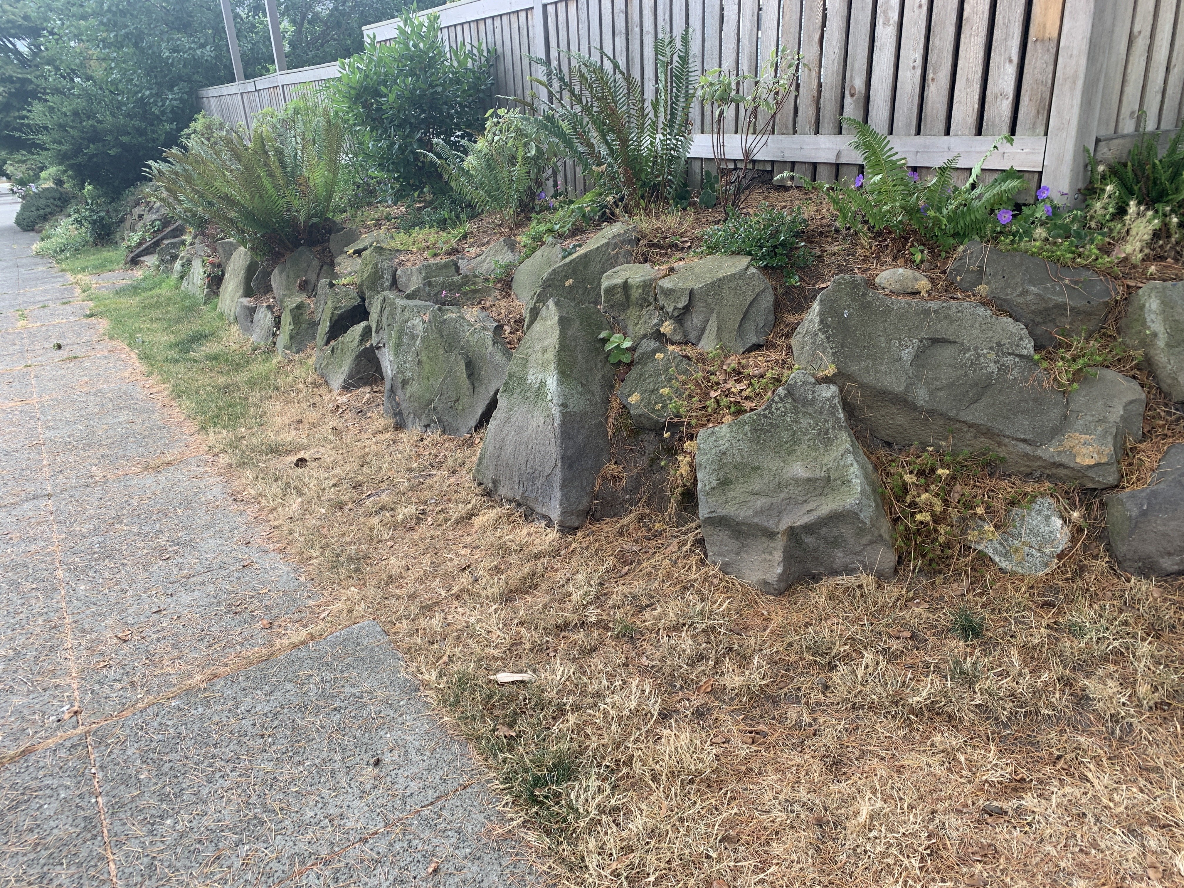
Most of the CAD boulders I see are kind of big lumps, balls of dough. We see those here, too, but many rocks in local landscapes are chunks broken from bigger chunks -little facets within or poking out of bigger facets, projecting edges, spalled ledges, etc. I suppose one could make a “swiss army” irregular mesh to push repeatedly into the dough balls and modify via Subtract Solids. But then vertex heavy objects. Sigh. Or maybe there are some good, efficient ones out there? -B

-
Ungroup usually takes them apart. Unless raster image pdf, which is only one layer. ungroup results in several objects- A blank or white rectangle in front of one or more groups full of vectors. Text is broken into polys see edit below Edit: the ungroup produces a bitmap (low res image) of the pdf, a blank/white rectangle and one or more groups of vector geometry. text seems to disappear. copy/paste of text from original pdf into vwx or into a text block in vwx causes a mashup of useless characters. -B
-
I see advantages with including everything in vwx. But I don't usually work this way because the vwx files get too cluttered and balky. I keep a project folder (MacOS) with sub folders for each phase. The sub folders have all the current vwx, notes, pdf, image, etc. This is from habit and I can easily navigate. But, I’m sole proprietor, so understand this workflow could be big problem if several or many teammates. -B
-
Correct, as usual! That’s another downside. @Darin K, a bit more info would help to define the problem and find a solution. How many different instances of the pipe are likely to occur? Will this symbol need a resize adjustment to many instances? Or will every instance require same pipe length so that adjustment to pipe length in symbol definition is solution? If former, another approach (total hassle) is to create a nested symbol, 3d only, of the assembly. Make the pipe and other components into separate hybrid symbols inside the container symbol definition. Ungroup any instance needing pipe resize and make asymmetric rescale to the pipe symbol instance. May need to rotate pipe to align x axis for the rescale, then unrotate (not testing here, just musing). Anyway, this could preserve the basic 2d elements. . . .But . . . Pipe 2d should also be adjusted to match new 3d length and prevent gaps or overlaps with adjacent objects. But are general purpose symbols or nested symbols actually offering an advantage in this workflow if the length varies in many instances? Might be better/faster to work with the source objects or hybrid symbols of the correctly sized objects. If only two or three different pipe lengths, then make a correctly sized symbol of each, or of each assembly. Symbol names indicate pipe lengths. -B
-
Here’s a way to handle: Select symbol instance on the drawing,Modify menu> Convert to group, edit the group to adjust pipe length. Exit the edit. Possible downside is that the object is now a group, no longer a symbol. Above process does not affect the symbol definition. The symbol will insert future instances as symbols with pipe too long. -B
-
Never heard of this, but would a test offer anything useful: In a duplicate of the file, try adding and subtracting layers from the 3 lists. eg: Add 3 layers to the DL list and see if 3 framing layers are eliminated. Add several Sheet Layers Delete several Design Layers and see if you can add some framing layers (or if the missing ones reappear). etc. Might be a workaround if some layers could be combined in the original file, or moved out to a separate file, then reference DLVP back in on a single layer? That list doesn't seem so long, so I'm surprised it's the limit. Hundreds or thousands might be a reasonable limit? -B
-
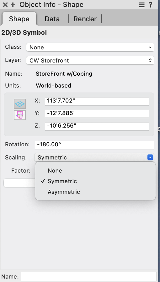
If the symbol instances (items on the drawing) will have varying scale . . . Select a symbol instance on the drawing which needs adjustmentf. In OIP, open the Scale menu and change from None to Symmetric (or Asymmetric) and enter scale factors as needed. This does not affect other instances on the drawing, nor any future instances (ie does not affect the symbol definition) Or If the goal is to change all existing instances and future instances to the new conditions, edit the symbol definition . . . Dbl click (or right click) a symbol instance on the drawing, or locate the symbol definition in the Resource Manager and right click the icon, then . . . Edit the 3d and 2d geometry as needed. Exit the edit to apply the changes to the symbol definition (the thing in the RM) and to all existing and future instances of this symbol. Annnd Michael beat me to it! -B
-
Adjust colors or at least adjust grey intensity. -B
-
Best site modifier to grade a sloping curved path?
Benson Shaw replied to JonKoch's topic in Site Design
Another idea is to place stakes or 3d loci with proper z values at ea grade point. Add the to the proposed source (or is this existing?) geometry. Update the DTM. Add some interior loci, stakes or even a grade network for crowning, etc. OR Dont put the loci /stakes in the source data. Instead . . . Draw NURBS curve (interpolation mode so the curve passes through the points) through all those perimeter loci. Edit the corner points with reshape tool to convert them to corners. Place this NURBS curve into the Site>DTM> Modifier class and update the DTM. May need some adjustments with loci, stakes or the Grade tool for cross grades. If needed add a grade limits around the new shape. Place a landscape area on it for texture and subgrade components. -B -
Also check scale and drawing pref for scale text. Dimension text could be too small to see unless zoom to it at center of the dim line. -B
-
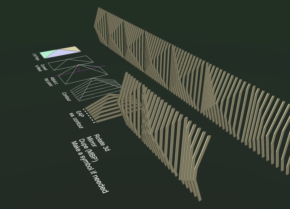
I meant vwx Subdivision. No Rhino here. Contour a surface created by any process to form faces, then shell works fine in some new tests with the faces in my earlier example. Earlier I found that the Shell has problems in a "W" shaped source face (current ones all shell to a concave direction). May not always work well. Shells sometimes self intersect and subtract a bit of the desired volume, esp at ends shorter than shell depth. Another disappointment is group editing. If single shell is selected, OIP identifies as Shell, and presents separate edit fields for thickness and shell depth. Selection of multiple shells - OIP only indicates count of objects and identifies them as Generic Solids - no edit fields. So, edits one by one. Similar problem with the EAPs. -B
-
@Tom W. all good! My goal was to represent dimensional lumber similar to @Ian Graham’s first image. The edge faces of the symbol in wall you show are chamfered to match the implied surface (plus full panel depth similar to second image). All of that may satisfy or even enhance the orig request. -B
-
I like the solutions! But they seem to map the front edge onto the implied surface. I went for contour of a surface, then EAP along the contours to model the lumber at constant profile. I'm not so good with SubD, and did not make this work. Any of you SubD experts care to post a solution to examine? -B SlatFence.vwx
-
Drawing Curve and identifying the curve wall deg
Benson Shaw replied to clng's topic in General Discussion
@clngWelcome! I went back to my drawing and looked closely at my "LED" units on the curve. Some of my snaps missed. So recommend care when snapping that second, rotation point. The reason I looked is that the angles should have been same for units on same leg of the curve in my video. I redid it, and found that if the snaps are correct, then the angles are same along each leg. . . except . . . Angels are not same, as expected, for units next to and/or spanning a tangent point between legs. I didn't try it, but I think a data tag at each point could use math to derive and display as text, the bracket angle from the segment angle. The angles can be called at any precision, but the vagaries of constructing a curve wall may make hash of that precision. Perhaps callouts could be presented as a generalized statement of acceptable range with guidance on required look of the completed array? Anyway, if inclined, post a render or a photo of the installed design. Many here would love to see it! -B -
How is it performing? No leaks, I hope. What was concept for transition areas? If you can reveal. -B
-
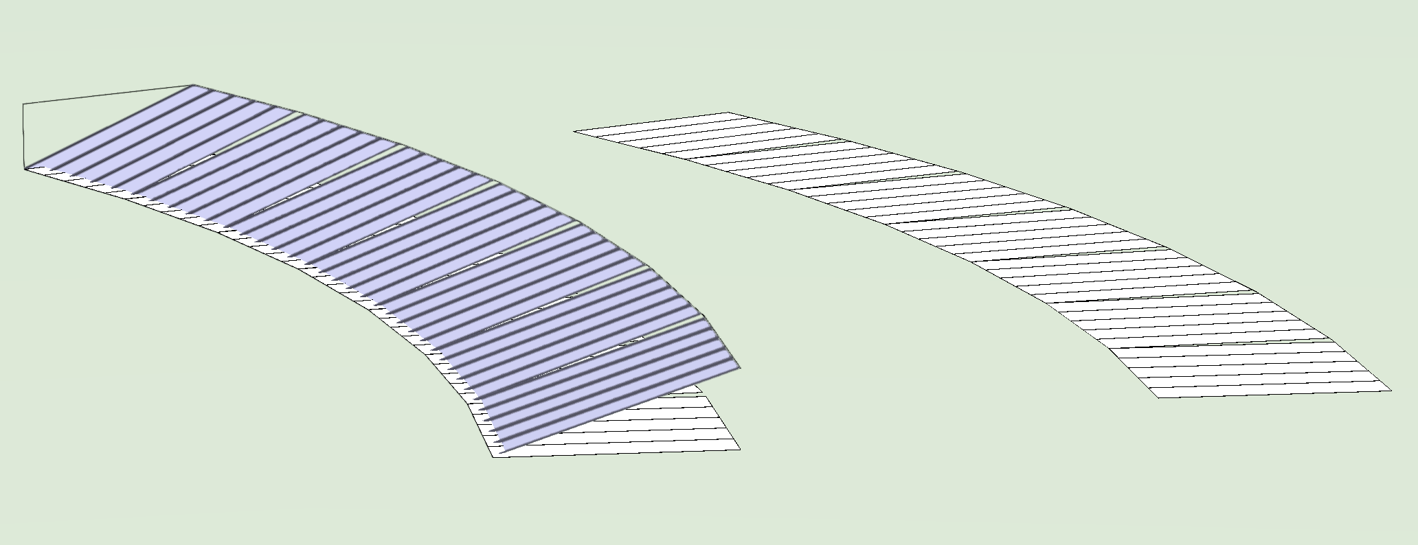
Adding to the mix, here. Several of the methods above are great for either radial or segmented. I think @CipesDesign frequent suggestion applies: model as it will be built. So ridge condition, roof slab, soffits, etc. And, since I don't know the construction detail, just shootin' from the hip with weather surface only, similar to @Tom W.. The transition between segments is full length to prevent cutting through any seams. Panels here have simplified seams (but they do interlock), made from NURBS loft, made to symbol, applied to 1st segment. 1st segment grouped and duplicate/rotate to other segments Transition material between segments is not addressed. -B

-
Just curious - What is construction method for such curved roofs? Does manufacturer create tapered panels? Or is there a field technique installers use to cut the taper and reform the edge to mate with adjacent seam? Or? Modeling might depend on constructibility. -B
-
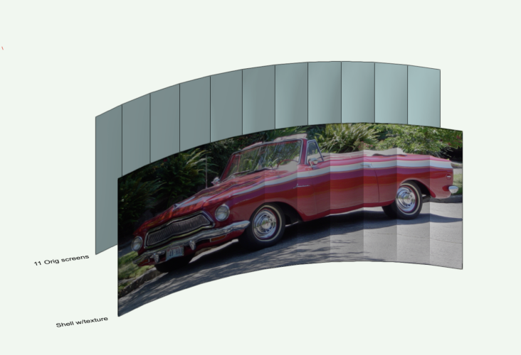
Use a cheat? Try the Shell tool in 3d Tool set. Shells comprised of several source surfaces texture as a single surface, in Plane Mapping. For safety, dupe the whole set of screens. Offset or move to a new layer. Engage the Shell tool. Set the thickness pref to something small - eg 5mm or 1", or . . . (adjust later as needed) Shell can grab many types of surface, even surfaces contained in groups or booleans. Click each screen with Shift key held until all screens are highlighted. Release the Shift Key. Click the green rectangle (upper left in Mode bar). Note: The original surfaces will be consumed by the Shell (hence the dupe). To retrieve them, Ungroup the Shell. Apply texture to the shell via OIP Render tab. Mapping = Plane Scale via slider or numeric as needed. Adjust texture position via Attribute Mapping tool. or numeric offsets. Front view best. Move the shell to match original position of the screens. -B
-
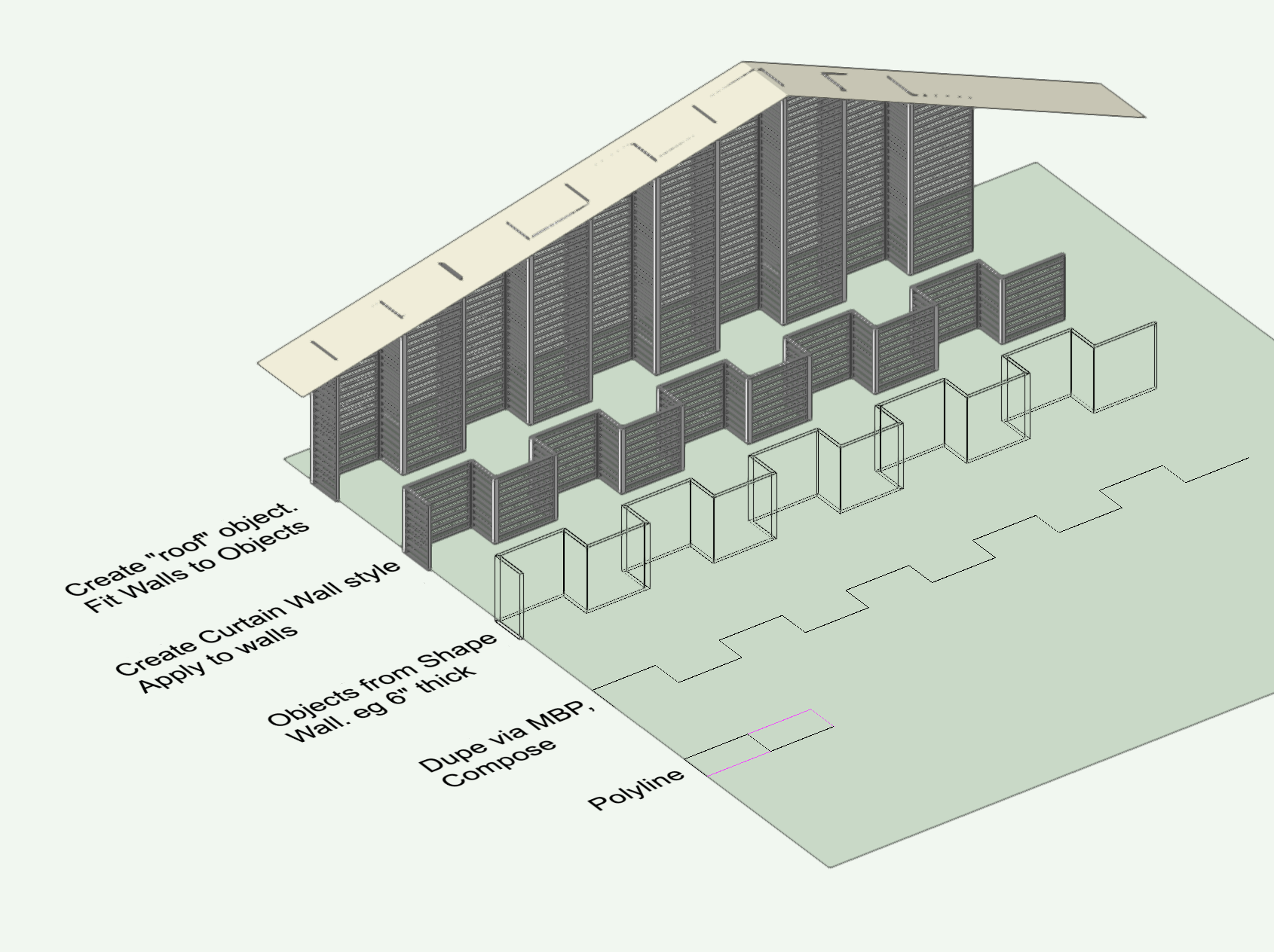
Doh! Jeff beat me to it. I've had some fun with curtain walls recently. Could work here. Make all panels Open to defeat the glass. Adjust the frame member dimensions. No caps might be best. -B

-
Drawing Curve and identifying the curve wall deg
Benson Shaw replied to clng's topic in General Discussion
Oops - no responses since Tuesday! Here's a clunky way to do these things. 1. The 6: My easiest, most controllable path is via the Polyline Tool>Tangent Arc mode. This is, I guess, more of a Volute than a spiral, but looks OK. Also possible with the Bezier and Spline modes, but more points to edit if not satisfied. The Spiral tool can also be a base object, but inner point shows uneven curve, and the flyaway "riser" breaks the regularly expanding spiral. So edit with split tool, rotate, add arcs, etc. big hassle. This curve can be transformed to a wall, via the Create Objects from Shapes>Walls. This creates a series of tangent curved walls. Can have components, openings, etc. If only 2d needed, use offset tool. 2. The angle/degree: I think you want the angle between LED units? This will vary at each pair because continuously varying curvature. But, to determine the angle between pairs, use the Angle Dimension tool>Reference Lines mode (3rd mode). See attached. 3. I think there might be a script floating around here for distributing things at constant length chords along a curved path. Anyone? The distribute tools use the arc length between stations. Eg Duplicate Along Path and Surface Array will leave spaces or overlaps at the joins, or stretch/compress the array items. I think doing it by hand with the Smart Cursor will be quickest in this situation. Create snap points by tabbing into the Length field and adding the chord value (width of array item). See attached. Good luck! -B The 6(1).mov The 6 - angles(1).mov -
Saved view page orientation restore relocates the user origin? Doesn’t seem like it would, but might be worth checking. -B