Benson Shaw
-
Posts
4,312 -
Joined
-
Last visited
Content Type
Profiles
Forums
Events
Articles
Marionette
Store
Everything posted by Benson Shaw
-
Bend an object along a nurb curve
Benson Shaw replied to Neves+Creative Inc.'s topic in General Discussion
@Neves+Creative Inc. Seems like two problems here. 1st is how to draw your intended design. 2nd is how to build to the design. I think best approach to drawing is extrudes. As you found, NURBS curves and surfaces resulting from Bend, Shell, etc have facets and snap issues at high zoom levels. The math is correct (OIP lengths, areas, etc), but the graphics can get confusing. Regarding draw - post back if help needed with any of this The Luaun, the stiles, the rails - all should be represented by extrudes of 2d Polylines or other 2d basic shapes. Start with a long poly (spline is fine) for the whole curve. To determine segment for each flat, place a locus and duplicate it along path with 10' interval (or 4' if flats are standup). Use the Split tool, point mode, to cut the poly into the smaller segments at each locus. Use each segment 3 times. Here are the basics: 1. Offset tool, Closed mode, 2.5" for the stile - extrude to 3/4" for the bottom stile. Later on, you will Duplicate and move z for top stile 2. Offset tool (other side of the poly), Closed mode, .125" for the sheet - extrude to 4' or 10' depending on orientation. 3A. Rectangle tool, 3 point rotated mode - Draw footprint of a rail (eg 2.5"x.75") on top surface of one end of the stile extrude. 3B. Duplicate Along Path (the flat segment), Tangent, Keep orig Position (uncheck the Center on Path). choose spacing or required number of rails. 3C. Extrude to height of flat less 2xstyle thickness (eg 1.5"). You may need to duplicate a rail and move/rotate to provide one at other end of stile. Regarding build I think many issues will point back to providing some tolerance. Different radii will produce different stretch/compress amounts of the 2 faces of the Lauan. Minimal amounts at 1/8", but noticeable on the drawing. I think not to worry. Design the frame stiles and rails to desired shape and dimension. When attaching Lauan to the frame, it may overhang (trim it!) or may come in shy (caulk or other filler). Because of real world material and craft variances, you will never achieve perfect fit. Lumber is not straight or even constant dimension. Cutting the curved styles (CNC? Jigsaw by hand? Routers?) will produce variances. Parts may not assemble without small gaps. Multiple parts of cut lumber may not be EXACT to the vwx design precision. Bending the sheets may not fit intimately to the (imperfect) curves. Sheets may not be perfectly square. The frames, even with braces and corner blocks may not be perfectly square, the bent sheet tension may bow or flex the frames, etc, etc, blah, blah, buuulah. Anyway, my advice, design and build the frames as close a possible to desired dimension. Trim or fill the sheet edges as needed. -B -
Texture is flipped when export as final renderworks image
Benson Shaw replied to htranbos's topic in General Discussion
Post a file with object(s) showing the flipped image textures. That suspended box has correct image, so guessing a model problem rather than a render setting. -B -
Long ago it was checked by default. A guess - Perhaps in your version to version up-saving the file vwx “remembered” and switched to the default setting. Especially suspect would be one or other of these past few versions defining certain features as legacy (phase out). -B
-
Making a 3d version of raised bed for planting
Benson Shaw replied to AMin1810's topic in Site Design
Yikes - no responses yet? Hope you solved already. Several ways to do this. Here is one way with basic Extrude Along Path. That final step with adjusting the location of the Profile is needed because vwx defaults to the center of the profile as the extrude datum. There are some workarounds, but this is the basics. Full shape of the profile is not revealed in the catalog. Does the bottom actually have that little return bend? Post again if more info needed. -B Planter.mov Raised Bed.vwx- 1 reply
-
- 1
-

-
Peter's post time signature showed "9 hours ago" when I viewed last night 12/24, 11:pm (west coast USA). Thinking that this was a Christmas eve tradition, I tried a restart for the annual joy before the midnight hour. Alas, no animation! Was I somehow not a good enough Vectorworkser ALL YEAR??? Realized that Peter must be way ahead in some earlier international time zone. Tried again in the morning of 12/25 local time. And there came the the elf in his sleigh drawn by the reindeer! YAY! (good boy, after all) -B
- 1 reply
-
- 1
-
-
I never tried before, but found that during local time on 12/25/xx, every Vectorworks quit/restart shows the animation. At least until the day times out. Or maybe if the reindeer get tired? -B
-
Random positioning of symbol within a defined area/volume
Benson Shaw replied to StudioVerma's question in Troubleshooting
Really great again! Found a typo in heading for random Y rotation. -B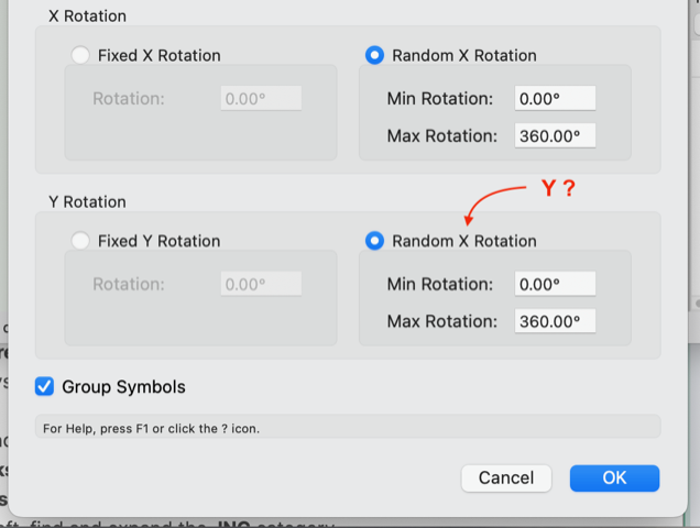
-
Random positioning of symbol within a defined area/volume
Benson Shaw replied to StudioVerma's question in Troubleshooting
Really nice! Many thanks for the work and clear instructions!!! Great results on 1st try. Couple comments: Rotation is around z axis. Enhancement? - 3d rotation to tumble the instances? Symbol selection and numeric values reset to defaults after each run. Enhancement? - Dialog "remembers" previous setting? -B -
Did you try the edit mode for Select Frame? Panel mode grabs the glass. Image looks like many extra frame sections around that panel. hth -B
-
I see this, too. Seems that the Center on View Change pref is not functioning between views in some (all?) edit panes. Another example is view shift between symbol Edit 3d Component and Wall Hole Component. -B
-
Funky, but another way is to create the new class by duplicating an existing class, one with desired attributes. Needs edit after creation to rename and adjust other aspects, but starting new likely requires similar edits. -B
-
Another thing to consider is construction and joining methods. There may be separate units which need to be created separately then connected via overlap, or hinge, or bevel, to create the desired joint. For your drawing, it may be better to shell subsets instead of making the entire assembly a single shell. If possible, work with the contractor to determine options and preferences. -B
-
@bcd did switching CRS to 27700 work? I think one needs to accept the transformation option when switching. If nothing else works, images, incl geotiffs, can be conformed (scale, rotate, stretch) in QGIS by locating a few known ground control points. This is in the Georeferencer tool. I think one of the polynomial transformation algorithms does the rubber sheet stretch. -B
-
Might not be same answer for every import because different softwares made the originals. Lots of that other software creates meshes, so import of any particular file may only produce hollow, (multi thousand) faceted object. Or, you might get lucky! If you internet search eg .sat vs .step the hive mind presents the origns/differences and MANY opinions. STEP is where I usually start. it’s a newer version of igs and can provide volumes as well as surfaces. DWG often meets my needs. the glide imports might be overly vertex heavy and might not be perfect representations anyway. Eg Mfg probably doesn’t want you reverse engineering their product. And therefore might be best as basis for modeling new ones in vwx? -B
-
How to create reference line in a model?
Benson Shaw replied to KenAB94662's topic in General Discussion
The screen plane concept is phased out, but available as Legacy 2d feature in Document Prefs. Enable it to control screen/working planes as in earlier versions. -B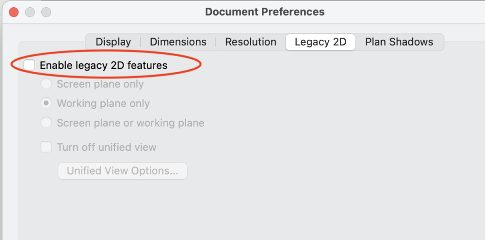
-
Duplicated contour line labels are a problem
Benson Shaw replied to Jeff Prince's topic in Site Design
@Poot thanks. This is path to label edits, move or delete them individually or all as a group. As asked by @Sameyers But I believe the issue of this overall thread stands ??? multiple labels return if the model is reset to show labels. So hand labeling via text or data tag for now? Or maybe one of those strategies in earlier posts can be forced in some way? Sigh. -B -
Duplicated contour line labels are a problem
Benson Shaw replied to Jeff Prince's topic in Site Design
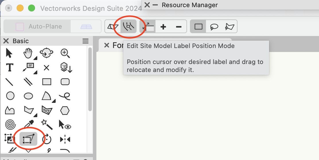
Edit Site Model Label Position Mode: Select the Site Model Activate the Reshape Tool (basic tool palette) Activate 2nd mode in the mode bar. -B
-
away fron keyboard right now, but I think these are all the steps: Select your “opening” symbol definition - the one in the Resource Manager. Right click, Edit 3d In the edit bar, choose Edit Wall Hole Component verify that the extrude is desired shape and size Exit the wall hole edit screen (return to the 3D edit screen) if the wood casing or other geometry is shown, delete any elements not needed. Add a 3d locus to help future placement of symbol instances. exit the edit pane if desired, edit the symbol 2d components and delete all geometry. This should also make the symbol instances identify as 3d symbols. Or create a brand new new symbol from a 3d Locus. Add the desired 3d object as the wall hole component. Either way, to use the cutting object, place an instance on the drawing and drag it into the wall. -B
-
Didn't mean to go off topic. Started a new thread addressing the NOAA point clouds. I though SP1 had this partially solved. Guess not. https://forum.vectorworks.net/index.php?/topic/111557-noaa-shapefiles-and-laz-do-not-import/ -B
-
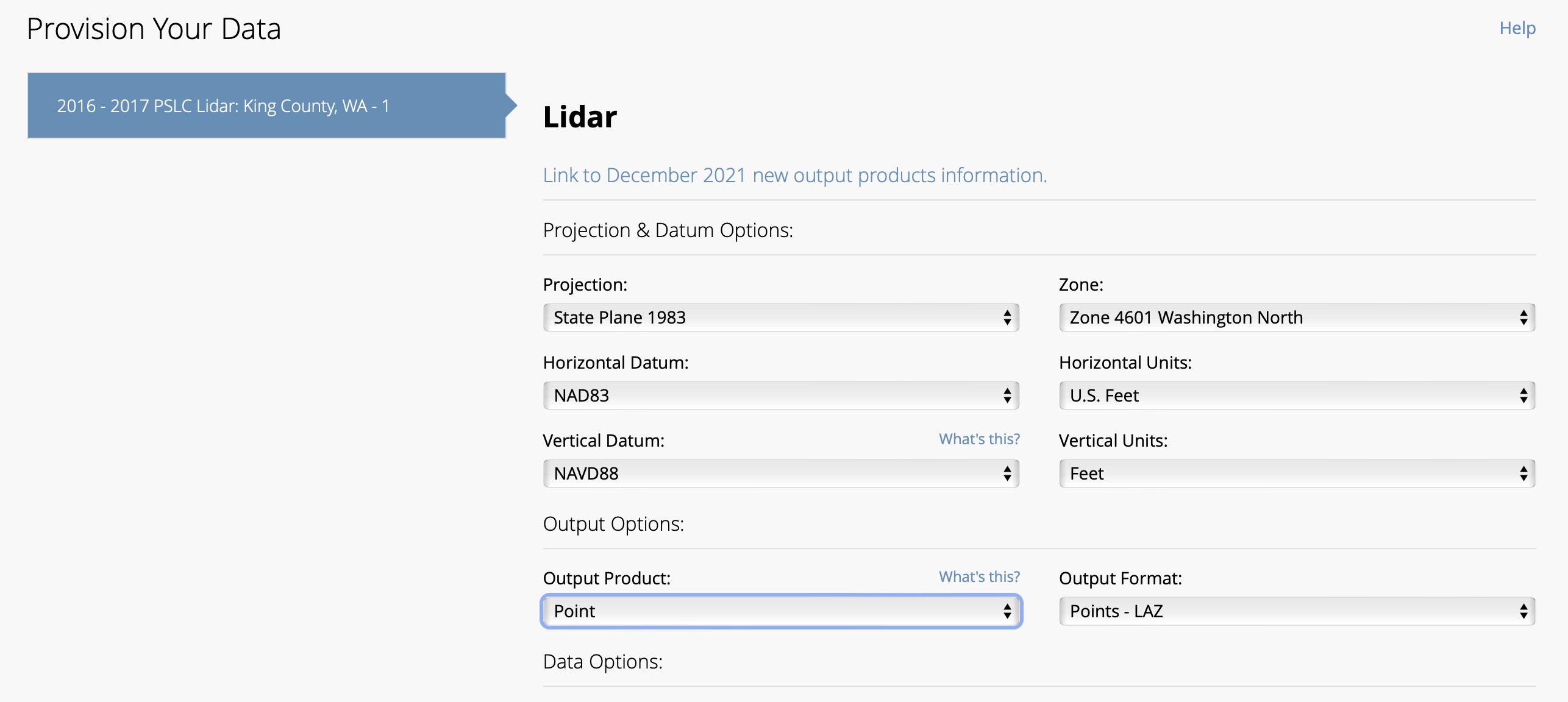
vwx2023 and vwx2024 produce error when trying to import NOAA Data Access Viewer shapefiles, LAZ and LAS point clouds. These all open OK in QGIS. I attach a couple zip files downloaded from the NOAA site. If anyone wants to test. OR grab your own from the NOAA Data Access Viewer site (search it). Job921534 is contours folder (SHP and support files) from a small portion of Seattle WA. Job 921535 is point cloud folder (LAZ and support files), same boundary, ground only. Image file shows the georef settings native to both SHP and LAZ Here is vwx detail from the LAZ file import: GIS ErrorLog.txt CPLErr( 3 ), err_no( 4 ) Unable to open /Users/bensonshaw/Desktop/NOAA Test/wa2016_pslc_king_Job921534/wa2016_pslc_king_Job921534.shx or /Users/bensonshaw/Desktop/NOAA Test/wa2016_pslc_king_Job921534/wa2016_pslc_king_Job921534.SHX. Set SHAPE_RESTORE_SHX config option to YES to restore or create it. Anyone know how to edit that SHX file config? Or why the file path shows twice? One with extension .shx, the other with SHX? file in the folder is lower case. Strangely, I collected similar area from the Data Access Viewer 3 years ago. NOAA might have changed something. Those earlier files import into vwx2024 and earlier. The SHP file conforms to (or establishes) the georef of my vwx file. The LAZ file imports, but at great distance (ignores the file georef) and needs rescale. If the contours and LAZ are captured from same area boundary, the LAZ can be accurately located and scaled to overlay the contours. Thanks - B wa2016_pslc_king_Job921534.zip wa2016_pslc_king_Job921535.zip

-
Not sure about ANY objects, or groups thereof, but. . . Similar behavior with LAS and LAZ point clouds imported to georeferenced vwx file (only tested with US NOAA files of terrain/ ground) . Scale and location waaay off. Group the point cloud and it jumps far away. -B
-
How to create lines which aren't constrained to a specific plane?
Benson Shaw replied to JacobH98's question in Troubleshooting
NURBS Curve tool in 3d Tool Set also produces non planar “linear” objects. Defaults to curvy vertices, but in Edit (dbl click) the Convert mode changes clicked vertex to a corner. (Or a corner to a curve). Guide objects for snaps are helpful. - B -
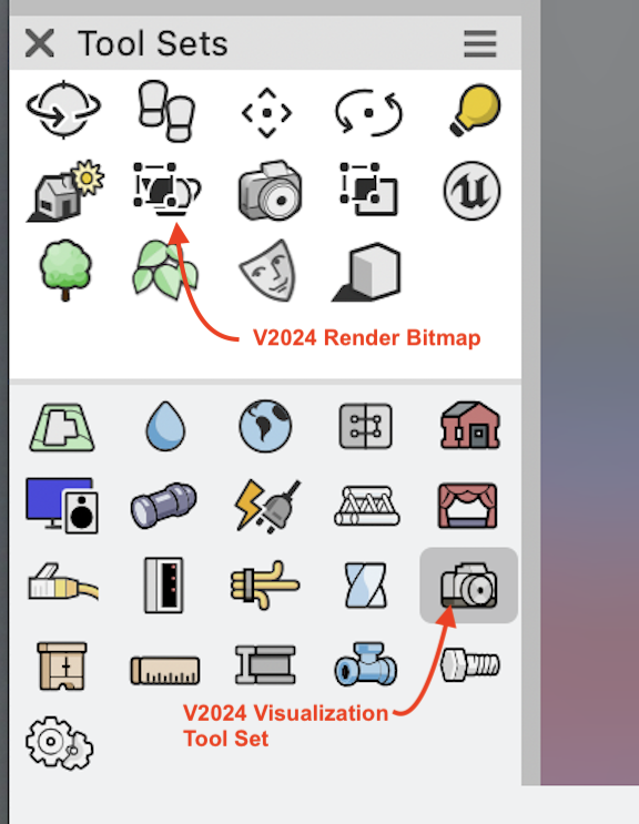
@Elite Exhibits Render Bitmap tool is in the Visualization Tool Set. New tool and tool set icons in v2024: -B
-
3d-Symbol distribution on a sphere object
Benson Shaw replied to bjoerka's topic in General Discussion
Actually, didn't say those initial descriptions very well. Rows and columns don't really apply. Should be more like this: Tiles are square extrudes, all same dimensions. Within each course, tiles are equally spaced. Gap width is prox 1/4 tile tile width. Neighboring tile edges are parallel. Adjacent courses are minimally separated. Tiles are centered on gap in neighbor course. As stated by @Kevin Allen - Something has to give. I think it can come close (fudged) in a small patch, but not over whole sphere or even large areas. -B