Jack2022
-
Posts
173 -
Joined
-
Last visited
Content Type
Profiles
Forums
Events
Articles
Marionette
Store
Everything posted by Jack2022
-

Section Viewports Again (Appearance of Landscape Areas)
Jack2022 replied to Jack2022's question in Troubleshooting
All visibilities seem to be the same. class layers. materials components. the only thing that may be the same is the landscape area name which it keeps warning me is the same... -
Section Viewports Again (Appearance of Landscape Areas)
Jack2022 posted a question in Troubleshooting
Hi All, I can't figure out why the section fills for the landscape area on the left of grid line C in the brick planter won't show but the one on the right does. They are different styles but same components and classes (just different depth profiles). Any Ideas? Thanks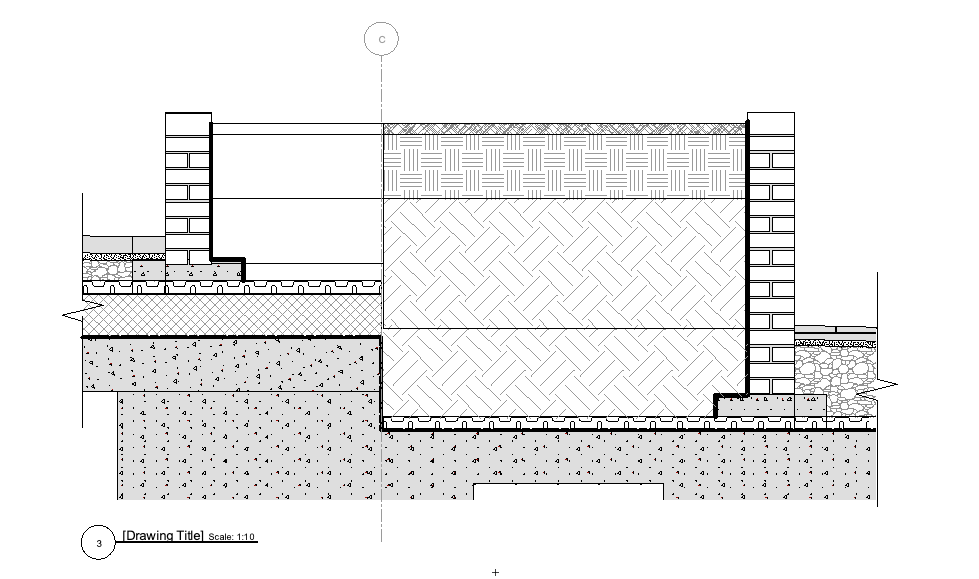
-
The answer was class visibilities in the viewports on the sheet layers. Despite all the different component classes being set to visible there was one component that showed up in the exported DWG. I set the class to invisible in the sheet viewports and it disappeared from the export. Not sure why only that class was visible in the first place though and not the others in the same slab object.
-
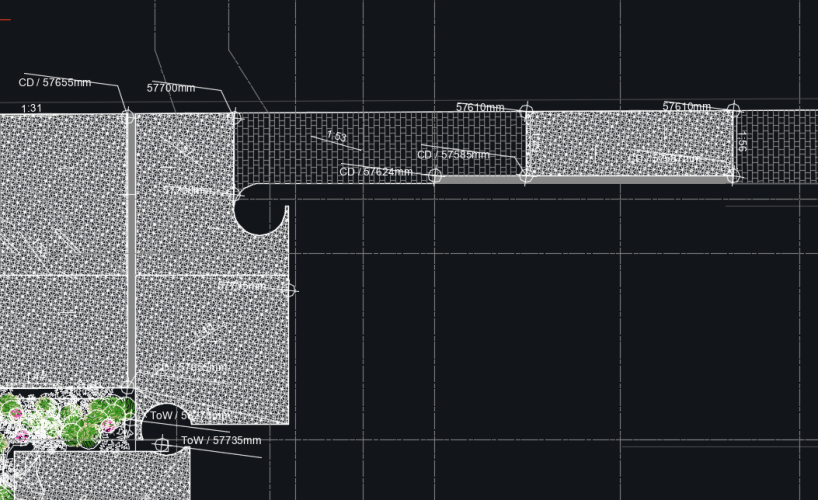
Hi All, Is there a way to export sheets as 2D DWGs without components of slabs coming in as separate blocks - I mean export without them entirely. I have used hardscapes and slabs. The hardscapes are just showing the surface hatch which is what I want for the slabs. The slabs are showing hatches for all the components. I can manually remove the slab components from the DWG file before issuing but this is onerous. Screen shot below of DWG model space. Thanks
-
Warning lines showing in pdf plot and viewport
Jack2022 replied to Jack2022's question in Troubleshooting
Thankyou! -
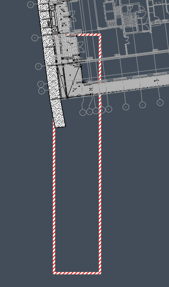
Hi All, is there a way to not show the white and red striped warning box in viewports/ pdf exports? I can't find the source for it as it doesn't seem to relate to an object in the model. Screen shot below: design layer in dark and pdf export in light background

-
Got it. Use grade tool. Set to ratio. Get rid of the line. provided you draw the start and end points from stake elevation marker to stake elevation marker it will pick up the stake values automatically so you don't need to manually type it in. Resolved
- 1 reply
-
- 1
-

-
Hi All, I am struggling to find a way to display surface falls on our levels plans. Is there an equivalent to the stage tool that can pick up surface falls from the model consisting on slabs and hardscapes? We need to show a ratio rather than the % default for slabs. So in essence we need to have an arrow and a figure - 1:40 for example. the grade tool doesn't appear to pick up the model levels. I'm aware this has come up before but there wasn't a solution and it was an old post. Thanks Jack
-
I've found the standard M1 suffers when in 3D view. It's fine for our model. Just the architect's buildings. And while running a file with references the ram usage frequently runs to 10gb and creeps up over time. Im not an expert but hoping we've solved those issues for the foreseeable.
-
I like your thinking
-
Yeah this is the second project we've been refused anything other than a Revit file. And the architects don't want to turn off or exclude from their export layers of furniture as it is apparently too onerous. It's easy for me to not export certain layers using IFC export so seems pretty unhelpful of them. The BEP says IFC and Revit for sharing and the coordinator is insisting on 1:1 modelling. Seems fishy. Anyway we've invested in 64gb M1 Max systems. fingers crossed that'll suffice.
-
Thanks Tom. as always I'll give it a go
-
Hi All, we have been enjoying Vectorworks now and receiving lots of help on the forum. Getting us up to speed (albeit shambling speed). We have M1 Macs (16gb) and for modelling our medium scale urban landscape projects this is fine - up to the point where the architect sends you their revit model for a massive building/ resi development, sinks, taps and all. At this point things grind to a halt. Usually impossible to import. Any architects on here use M series Macs to power large building models? 100 resi units upward. What specs work for you? Jack
-
Hi Tom, looks very promising. How do modifiers work this context? So far I've only used stake modifiers to get surface falls on a hard scape. If you can bare to persist with my questions could you describe how you did it? How editable is the slab now? If I reshape the plan area to follow architectural changes will it survive as intended? thanks
-
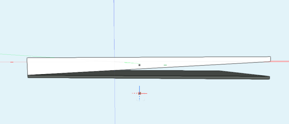
Hi All, This came up in another discussion but I wanted to focus in on the one issue. The screen shot below is a slab that I subtracted a wedge shape from. When I add a component to the bottom it comes in flat rather than following the bottom profile of the top slab component. Is there a way to set the bottom component to follow the underside of the top without crating a separate slab or hardscape? Thanks,
-
Thanks Tom, Ill investigate extract surface. I think although clunky, we're close enough to a solution. Easier to model this solution knowing in advance of setting all the slab falls so will be using it on our other project I think. The BIM manager on this one will have to settle for annotations tidying up the sections I think. (We are being strongly encouraged to model 1:1 which in my view is pretty impossible with landscape). I'll update with results once i've tried extract surface. Kind regards, Jack
-
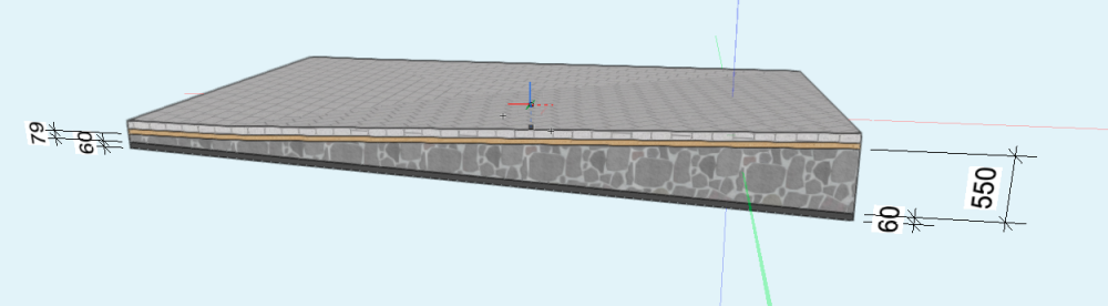
This is possible but I had to draw a 3D polygon around the bottom of the sub base component and create a mesh 60mm thick on the bottom. then add material to it. Bit time consuming and the black mesh part isnt editable when the slab is edited. Half a solution. If you have any other ideas then do let me know.
-
Im trying to get the top mid grey surface to fall in one direction while the bottom black component falls another. The only component that can vary in depth is the light grey which in this case is sub base. I can add fills to any of the components but if its a mid layer component then the component below it doesn't adjust to the modification as per my previous picture. The black layer needs to be a consistent 60mm thick to falls sit-in under the modified component. I think the implication is don't include the black element in the style and add its separately to the bottom of the style as its now slab or hardscape? but then this is very time consuming making a separate hardscape bottom element for every instance of this paving condition.
-
Hi Tom, Very close! I'm getting this though - the bottom component which needs to be a fixed thickness doesn't add itself back to the modified component. This suggests the drainage board might need to modelled separately as its own slab or hardscape. Which is very onerous! Maybe theres a setting to allow it to align again?

-
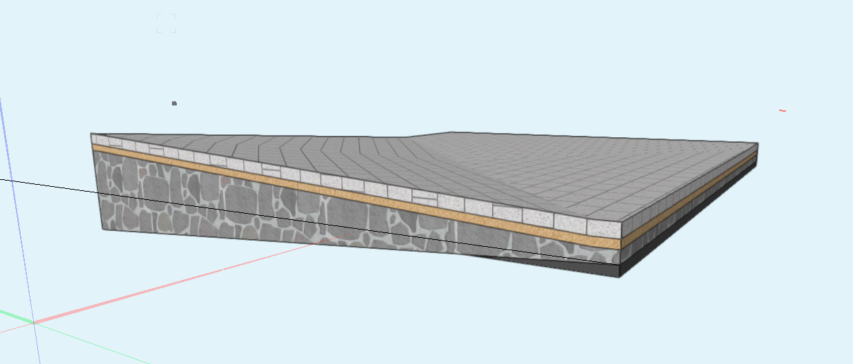
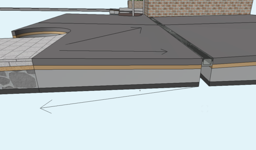
Hi All, I am trying to accomplish the following: An area of paving with a few build-up components where the surface needs to follow multiple directional falls to achieve surface drainage - while the bottom component needs to be set to different levels as the paving is sitting on a concrete structure - sometimes sloped sometimes flat. Hardscapes easily provide complex sloping top component surfaces using stake modifiers but the components are all a fixed thickness and follow the surface levels (ie the tapered component option doesn't work unless you convert to slab/slab drainage style- see below). or Slabs with Slab Drainage which allows you to set the bottom component level and grade the top component surface as required. Only issue with this method is the bottom component level can only be flat as far as I can tell. This is almost great but lack being able to follow a sloped bottom base. I would like the Drainage Slab option but be able to have the bottom component be able to slope itself. Or have a hardscape that can have a proper tapered component and you can adjust both the top surface levels and bottom surface levels. Is it possible? To simplify I'm after a tool that allows the top components to follow one set of slopes while the bottom follows another and the middle tapered component takes up the change in thickness. Whatever is the solution it needs to be a tool so its easily adjustable going forward. Using fixed meshes or polygons or solids would be too onerous to try and adjust every time the engineer or architect change something. Which as any UK Landscape Architect will tell you, happens all the time. Thanks
-
I may have exhausted any help I'll get on this but I have found a solution that is both simple but also feels a bit vulnerable to mess-ups. Make sure your User Origin is temporarily aligned to the Internal Origin. Import their model. Provided your Internal Origins are aligned which on this project both ours and the architect are (even though they have a Revit project base point (I don't know why they are still aligned to my default 0,0 Internal Origin but they are)) then that will be the position they want you to align to. Set your UO back to the relative position to give you true coordinates in your file that is aligned true north. Draw a cross or symbol at the UO so you can move both this and your model and retain a marker to align the UO with after moving. Move the UO cross/symbol and your model over the Architect's Revit model using common reference point - ideally building grid. Rotate your model to match the architect's alignment (losing your NE coordinates in the rotation). Make a note of the exact rotation angle. Set your UO to the cross/symbol Now if you read off a coordinate it will be wrong because the UO doesn't rotate like this. Use the axis tool at the top of the screen to change the top plan angle of view to true north (using the rotation angle noted earlier). This is very similar to UCS in AutoCad. Might need to rotate the axis around the Internal Origin but not sure yet. Now your coordinates will be correct again because the coordinate system follows the axis tool rotation. The only issue is the axis view rotation keeps defaulting back to true north when I change view. Maybe there is a way to lock the axis for design layers or something? Thankfully the architecture practice on another project has aligned their building to true north and uses real world location so we won't have to do this dance. Thanks all for previous help.
-
I've read a few posts about the lack of ability to rotate textures on slabs. Is this still the case in 2022? I need to use slabs for the drainage function and the constraints of the project. Many thanks, Jack
-
Ok thanks
-
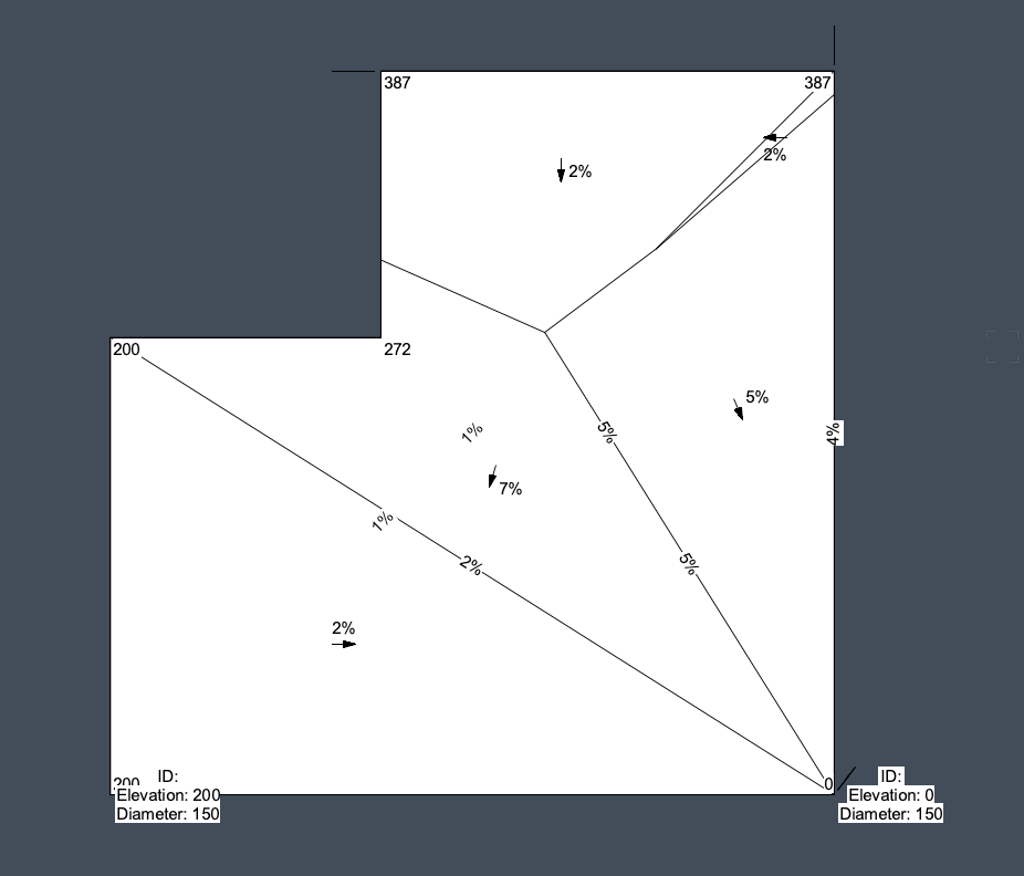
Quite right Tom. I didn't explore slab drainage enough before moving on. Any advice on showing the grades as ratio not %? Thanks
-
Hi All, I had raised the issue of how to make a hardscape have a tapered component before and the result was that they can't. i.e they can't have a sloped top and a fixed bottom. Well I've just found the solution which is slab drainage! Brilliant! Question: in the UK we show falls as a ratio not percentage. Is it possible to show the falls/ gradients as a 1:x ratio?? Many thanks.