Jack2022
-
Posts
174 -
Joined
-
Last visited
Content Type
Profiles
Forums
Events
Articles
Marionette
Store
Everything posted by Jack2022
-
I think I've sorted it. In new file just import their georeferenced drawing with their Revit Internal Origin identified. Select Geo-reference tool click their Internal Origin point so the Internal Origins are aligned. Adjust the User Origin to compensate and maintain real world coords.
-
Its imported as meshes. Often grouped
-
Sorry Its confidential
-
I have no option. I am required contractually to align my coordinates with the Architect's Revit coordinates so no movement is required when models are shared between different consultants. We have a few projects on the go in VW and the one I'm in is in its infancy so no big deal to move stuff around.
-
I think you may be misunderstanding me (or I am misunderstanding you). My model is already at the internal origin even thought the real world position is far away. I have already set the user origin to compensate so the coordinates are correct. What I need to do is change the coordinates of Internal Origin for the file. Revit doesn't recognise the User Origin from Vectorworks. Only the Internal Origin. Hence me needing to change the real world position of the Internal Origin I suspect the solution can be found in georeferencing but I cannot find a clear description.
-
Hi Hans, thanks for your input. I might not have explained myself properly - I will move the model onto the new internal origin manually once I have changed the internal origin position to match the internal origin of the Revit user. The problem is I can't find how to change the internal origin so it matches the coordinates provided to me by the Architect.
-
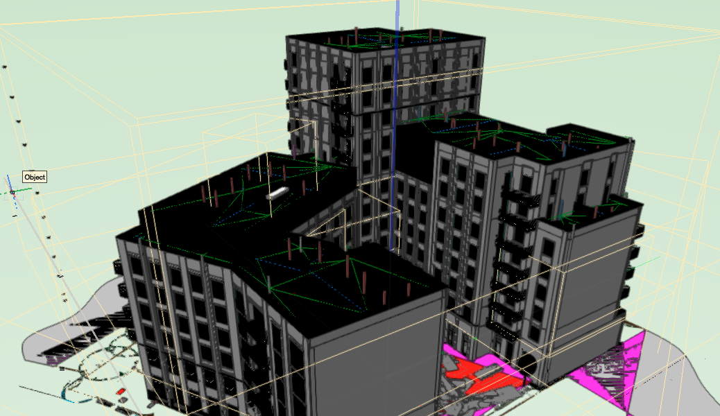
This has been raised before but I couldn't see a solution. Is there a way to import Revit files with default white attributes? Across multiple projects the objects within Revit model imports have black as their default fill attribute. Image below. In principle selecting meshes and changing fill attribute does work but totally impractical (hours of unpaid work). Thanks for any help.

-
Hi All, I understand how User Origins work and how to change the User Origin to maintain true coordinates regardless of model position. What I don't understand is how to change the Internal Origin. We work across multiple external consultants who typically use Revit. While changing the User Origin works nicely for some software (CAD, Navisworks) Revit is of course a special case. We need to change our Internal Origin to the shared project coordinates so our model imports exactly in the correct position set by the Architect using Revit. Is there a simple step by step? I want to change my Internal Origin to a new X,Y coordinate. Then I will change the User Origin to maintain true coordinates. All the videos say more long-winded and complicated info. Thanks
-
Thanks both. I've come to discover when you use site models Landscape Areas and plants need to be Z0 and the site model doest the work. If it doesn't work - recreate stuff.
-
Hi All, I'm struggling to understand how trees work on site models. If I give a tree a Z value it doesn't correspond to the site model level. For the tree Z0 is Z0 but the tree either comes in way too low or high when I give it the same Z value as the site model. Is it something to do with send to surface? If I tell the tree to send to surface nothing happens. Any help would be much appreciated. Jack
-
thanks
-
Hopefully a simple one. How can I add a symbol to a favourites folder? I can make a favourites folder but I can't drag the symbol into it not can I export a symbol to it. I can attempt a drag but nothing happens. Thanks all.
-
Oh and decent landscape walls
-
You are of course correct. I am actually enjoying Vectorworks quite a lot as software goes and it is the best offering for landscape. Just tapered components for hardscapes (retaining stake modifier capability) and a kerb tool and it'll be complete!
-
Sorry - should have said. These are slabs. The valley lines are effectively the same as the outline so if I change the attributes so the pen is faint or off then I lose the outline too. Modelling in 3D for BIM then drawing over defeats the object really and adds extra time to workflow. BIM only really works if additional 2D linework is kept to a minimum (annotating viewports for eg). It looks like VW could add a button, much like for slope values and arrows to put the lines on a hidden class. Oh well! I am finding crazy obvious gaps in VW functionality every day. It feels like they could bin off 50% of their functions/ dialog boxes and make massive improvements to the tools (which a lot I really like). By improvements I mean simplifying. Not providing 3/4 different ways to do the same thing. We shouldn't be expected to be professional designers AND software engineers. The problem with BIM software is the apparent infinite functionality at the expense of accessibility and usability for 90% of professional's workflow. How can we expect to skill up a junior workforce (and make sure quality is maintained) with all these endless options at our fingertips. Also I have endless random behaviour glitches in viewports. Usually between two identical objects with same properties. Don't get me started on exporting to DWG. Why is that so complicated yet doesn't get a neat clean and concise export! Classes within classes within classes with attributes and overrides. Too much opportunity for error especially with multiple people working on a project at different confidence levels with the software. Rant over. Probably just my selfish desire for a perfect piece of software for my personal needs. Putting major pressure on deadlines trying to find reasons for random glitchy behaviour. Landmark seems stuck between pure architecture and civil engineering tools and still missing the classic Landscape Architecture needs. The mid scale. I'd buy a massive pint for anyone that allows tapered components in hardscapes! and a Kerb tool!!! Thanks all for your input.
-
Would be good if possible. fading the layer pen in viewport layer overrides works but then that creates other visibility considerations.
-
Thanks, it is top/plan view. Hopefully its just a click of a button
-
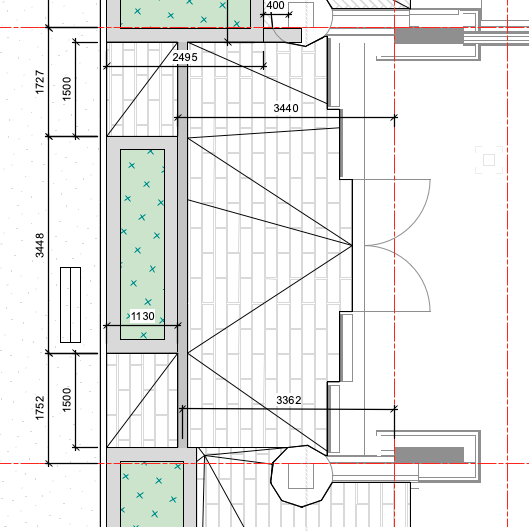
Hi All, Slab drainage lines are making my drawing look messy. Is there a way I can hide them? screen shot below.
-
The project team agree IFCs for clash detection and issuing to the client for COBIE stuff but for internal team coordination its 2D DWGs and 3D Revits. I'm yet to see a project where IFCs are the main sharing format for detail coordination. I'm just sticking to DWGs. Revits don't import with 2D graphics anyway so useless in 2D views. They just look like a meshy mess.
-
 Hi, Most of our projects and maybe most landscape projects in dense cities like London involve landscapes on rooftops or podiums. As such it would be essential to be able to fix the bottom datum of landscape areas, site models and hardscapes and have a component taper (e.g subsoil, sub base, void former). At the moment we have to use: Hardscapes but the components follow the surface so the 3D model shows a void under the hardscape and you can't take true volume calcs for the sub base materials. Site models to create mounds overlayed with landscape areas to provide topsoil volumes (but as the landscape area components don't taper you have to use the displaced site model volume as the subsoil (and you can't give site model fill a material so there's no true sub soil data). Landscape areas for ground level planting or areas on roof with fixed thicknesses of soil (ie no mounding or contouring). It seems to me like a fundamental need for landscape architecture. The dialogue boxes say you can taper but it doesn't actually work!? Thanks, Jack
 -
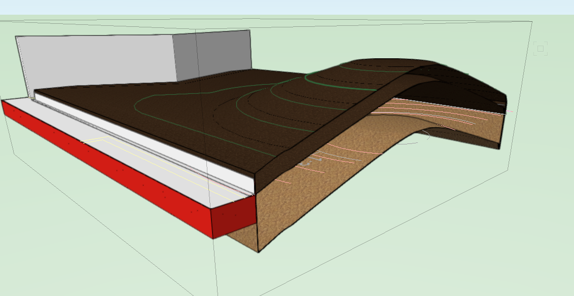
Ah right. Thanks for trying. Ive found a poor way. It doesn't allow you to have a material for the subsoil - just the topsoil. But it does allow you to see the volume of the total soil (site model total) and the displacement by topsoil Screen shot below. So you can take the site model volume as subsoil. I did it by dropping a landscape area of a single topsoil component onto the site model. As we want two topsoil depths for our situation I just added another landscape area style with deeper topsoil onto both the site model and the first landscape area. the cut and fill added this in to the calculation. I would be careful reading the volume off a landscape area though! The datum level vs min level and max level seems to be very inconsistent and gives varying volumes and skirt depths despite two different duplicate landscape areas having the same settings! Ideally you would be able to specify the material for the site model fill but I can't find a way.
-
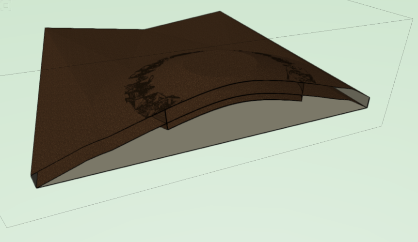
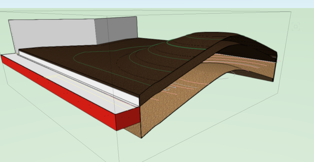
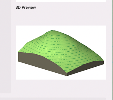
Hi All, this is similar to older posts I've raised but different as it refers to Site Models specifically. Our required soil build us consist of 300mm topsoil over variable subsoil depths. Is there a way to represent this in site model components? The mound is on a roof so level bottom surface. Image below. The site model 3D preview in the dialog box implies you can have a flat base and variable depth soil. I want it to look like the 3D preview only be able to have the top 300mm as topsoil and the rest subsoil. Thanks, Jack
-
Just realised this has been covered in painstaking detail elsewhere. If you're on Mac you just have to suck it up or change everything and go Threadripper.
-
Ok I can confirm importing Revit files is still hit and miss with the improved hardware set-up. Importing one Architect's building seems to have been improved time wise (medium size apartment block - 270mb) but the building on another project which is 3 times the size (but less file size at the moment (150mb)) doesn't import. I gave up after 2 hours. Considering sharing Revit files is the norm in UK BIM projects this is a concern. Doubly so as the hardware we are using is pretty much maxed out unless we start using M1 Ultra processors which is out of reach for most. Obviously once imported the improved hardware comes into effect and manipulating the buildings is smooth. Is Vectorworks not exploiting the hardware properly?
-
For some reason this is the most basic requirement for landscape architects and garden designers yet there isn't a simple kerb or edging tool where you can dynamically extrude a profile along a 3D path. With components for haunches too! A bit like the Framing tool where you can use a symbol as the sectional profile and extend it as required. Framing tool is only for straight lines though and can only change its Z value as a pitch in degrees. Something that sits independent of roads or hardscapes and slabs as we usually don't want it linked to these as usually the kerb needs to respond to a variety of contextual objects.