


Jack2022
-
Posts
173 -
Joined
-
Last visited
Content Type
Profiles
Forums
Events
Articles
Marionette
Store
Posts posted by Jack2022
-
-
Thanks Thomas - will consider floor /level heights as the Z base value on the next one.
-
Hi All,
Is there a tool to create wall piers for free standing landscape walls? I have googled but no hits. Not sure if these are called something else in the U.S. perhaps.
Thanks,
Jack
-
Thanks Tamsin - I will have a go with these tools.
Kind regards,
Jack
-
Hi All,
I have recently switched from using aligned hardscapes to draped hardscapes with a site model modified by using grades.
Generally it works great!
Issue with curved pathways: Is the simplest way to create a curved fall in the site model via nurbs curves set to the DTM class? I saw on one thread where that was suggested.
It is ok just a pain when you are modelling top and bottom of kerbs along a falling curve. Also a pain on designs with lots of curves.
Maybe a way to create curved grades??
Regards,
Jack
-
Thanks Tamsin - all clear. And it works great now!
-
 1
1
-
 1
1
-
-
Ah - no I don't. Placing a grade limit around the whole site model seems to have resolved it. Grade limits were mentioned on the other thread but not explicitly that you need one around the outside of the entire site to make the grades work as expected (in my case the whole site will be modified hence around the whole site).
Many - thanks. This should speed things up no-end.
-
Hi All,
This is an issue from another post but it seems to have become lost in a wider discussion there so posting in isolation here.
I am hoping to make my workflow more efficient by using site models more. Instead of using stake objects and aligned hardscapes I hope to modify site models using grades and stakes and have hardscapes drape onto the site model.
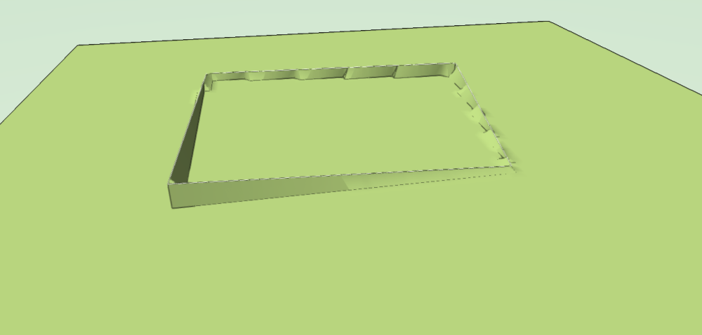
When I link 4 grades to make a square area the centre of the square sits at existing levels instead of an elevated surface inferred between grade points (as I would expect an aligned hardscape to behave between stakes). I understand that this shouldn't happen if the grades are linked.
Am I missing a key step? Image below. modifier grades and site model on same layer.
Many thanks,
Jack
-
Found the answer:
you cant fillet while having the plan rotated.
-
 1
1
-
-
Hi All,
hopefully a simple one.
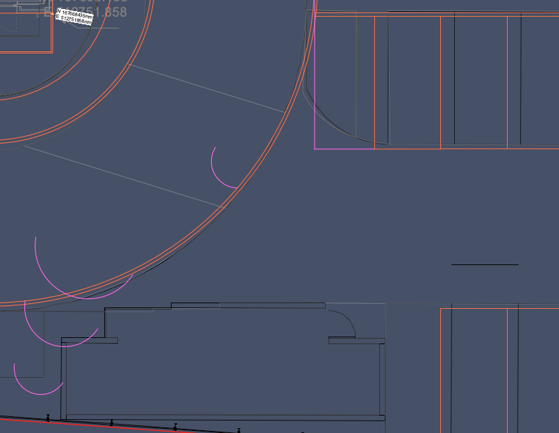
When I Fillet two lines at 90 degrees to each other the resulting fillet appears far from the the expected location. Screen shots below:
Lines filleted are in purple and the arcs shown too. This happens quite often for me.
Any thoughts?
-
Thanks Tamsin.
I now understand that part. I ended up editing my post to narrow down my issues.
Are you able to help with my issues? As far as I can tell I have followed previous advice but the issues remain unless i'm missing a key step!
Kind regards,
Jack
-
@PNWPaul seems to have solved the problem I'm having but I am not really clear on how.
I don't really understand the contribution of the Grade Limits tool in this case.
My grades are definitely linked but the middle of the square remains at existing height. Same happens for any shape I try.
My entire site model will be regraded as no parts of the site will be retained as existing. As such I dont think grade limits apply.
Also setting the site model to align to a different layer than objects on its own layer really doesn't seem to work either. I place my site model on one layer, draw grades on another, set site model to align to that layer in its settings and nothing happens after an update. Only works if grade objects/site modifiers are on the same layer as the site model.
Many thanks for any help. .
-
Interesting discussion all.
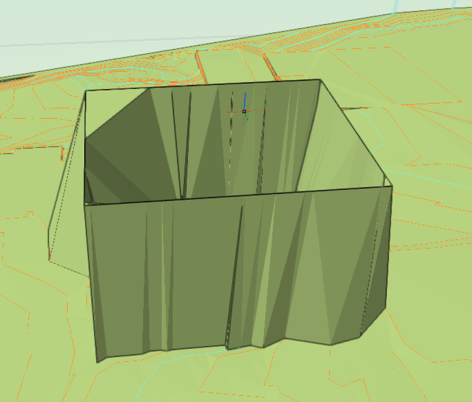
I have been practicing using stakes and grades to set the site model as recommended. I am not yet sure how this will work with curved footpaths as I use Interpolate a lot for hardscapes with curves and site models don't seem to infer between stakes.
I have found that unlike hardscapes, site models dont seem to infer between stakes. they just grade to existing very steeply. I suppose grades do this job.
Example below is a square area with stakes on corners and grades between. Why doesn't it create a plateau?
Also:
Do grades and stakes need to be on the same layer as the site model? I changed the setting of the site model to choose an alignment layer but it loses its relationship to the grades and stakes.
-
Thanks Tamsin,
due to the nature of most of our projects we tend not to use site models as most of our urban brown field site surfaces are replaced with paving or planting. For both we use hardscapes as we find the stake modifier the simplest method to get falls in multiple directions on one surface. I understand Landscape Areas can align to falls but only if the site model is present and correctly sloped between hardscapes. We don't tend to use site models as we don't model kerbs (exhaustive to change when levels are inevitably amended through the project stages). Without kerbs the site model pops up to existing level between hardscapes so we don't bother using site models.
One thing thats been bugging me about levels is we use stakes set to 2D/3D graphic only in the design layer to create our levels plans (with grades showing falls between stakes). To create the 3D hardscapes we then need to do it all over again in the hardscape surface modifier mode. The reason we do it in '2D/3D graphic only' first is we can use line tools and dims to measure and work out the levels and gradients. In hardscape surface modifier mode you don't have access to measuring tools for distances.
Perhaps we need to start using site models, using grades and stakes there with hardscapes and landscape areas are set to drape. Rather than building the hardscapes then trying to get the site model to align to them.
Thanks again,
Jack
-
Finding bad hardscapes resolved the moray issue and it now looks good. Still takes a long time to update site model but once done I it looks correct.
Some hardscapes had thin extensions down to 0 where stakes were poorly aligned.
I didn't know you could crop site models so will try in an idle moment in the future.
I was sure there was a way to snap/align to top of hardscape or bottom. Can you remind me where? struggling to find via google.
-
1 minute ago, Jeff Prince said:
you can get them to meet cleanly by including data beyond the edge of your desired site model and then set your crop at the desired edge of the model. That being said, your site model doesn’t look so large as to require such an approach, it probably just needs to be cleaned up and checked for inefficiencies.Thanks Jeff,
good to know it's worth me checking through everything. Due to the design we have inherited the parking bays are individual hardscapes (excessive edging courses so using borders) which may be causing headaches for VW. Will audit for errors though.
-
1
-
-
Hi All,
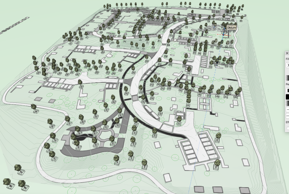
We have a large scheme (in area rather than density).
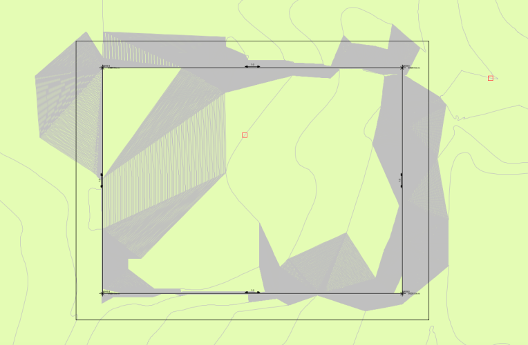
We have modelled the hard landscape using aligned hardscapes with site modifier stakes to get each hardscape to fall correctly with multi-directional falls. The site model will only update the proposed 3D topography if it is on the same layer as the hardscapes. When it does it displays too much moraying on the hardscapes to be useful. The hardscapes also do not cut the site model even when set to do so. Updating has no effect.
Questions:
- Should I be able to choose a layer for the site model to align to? I thought this was a new feature but it doesn't work. I have followed this process but the model only aligns if on the same layer as hardscapes.
- Are there better, slicker, newer methods to create paved areas that can slope in multiple directions other than aligned hardscapes with stake modifiers? This method works well for us but aware things have changed a little in 2024.
- It takes a long time for the site model to update to align with the hardscapes. Is the model just too large an area with too many separate hardscapes? Screen grab below. Note the site model is not aligned in the screen grab.
I have tried to split the site model into 4 to reduce load on VW but the edges don't meet cleanly where the cut in contours were made.

Kind regards,
Jack
-
Thank you both. Will look at how 2024 Update 4 has changed.
I believe I have solved the problem - our Internal Origin coords were not aligned with the Architect's (school boy error). Not sure why the IFC imports as a different coord system when I try it but it is now correct on our project.
@Poot - the unit precision didn't help unfortunately.
To Answer your question about origins - Revit only recognises the Internal Origin so we change ours to match the Revit user's Internal Origin which should also be the agreed Project Base Point. Otherwise our models won't arrive in the correct space when they import them. It's fine for other software like Autocad and various BIM clash softwares as these all use the User Origin (which should be 0,0 British National Grid to arrive in the correct place (if British project). Unfortunately I'm yet to come across an Architect who isn't a Revit user in a BIM situation.
Secondly I understand it is good practice to keep the Internal Origin close to the model otherwise you get bugs.
-
1
-
-
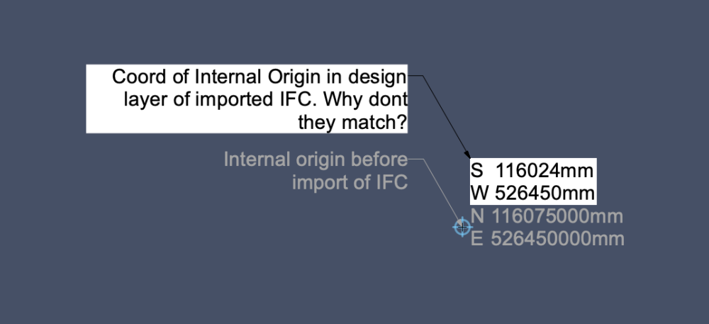
Hi All,
Our model is georeferenced to shared project coordinates. The internal origin is set to match the lead consultant project coordinate and the user origin is set to British National Grid 0,0. We use Nothing and Easting coords.
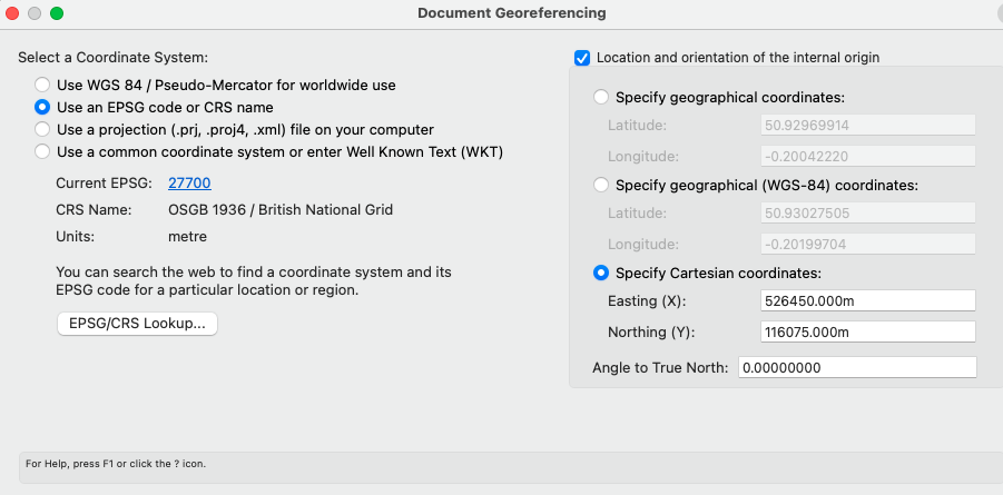
The Architect on the project told us our IFC export isn't arriving in their model in the correct location - our DWGs do and design layer coords match in our main model.
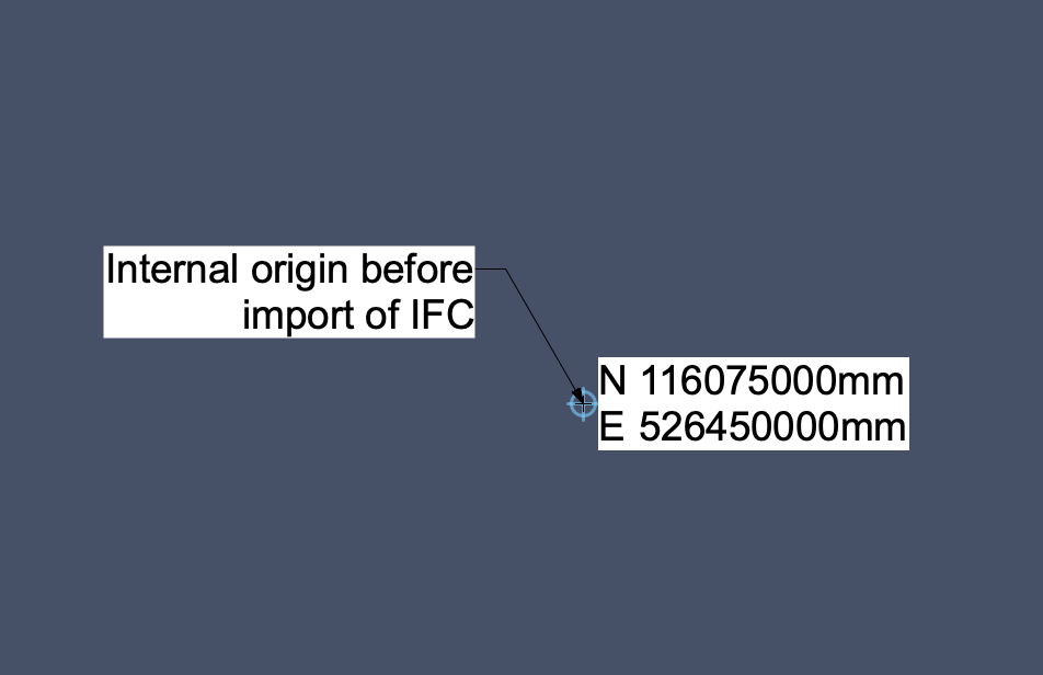
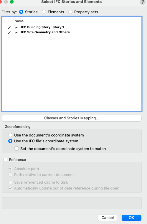
When I import my own exported IFC file into a correctly georeferenced empty file and select 'use IFC file coordinate system' in the import menu it is indeed wrong. When I use a N/E coord stake on the internal origin of the design layer with the IFC it shows as a South / West coordinate that does not match the X/Y coord.
N/E coord matches the X/Y coord in the georeferenced import file before import:
Import settings:

On investigation the only thing I can find to affect the IFC coords is something called 'Reference Latitude' and 'Reference Longitude' under Site Data in export settings.
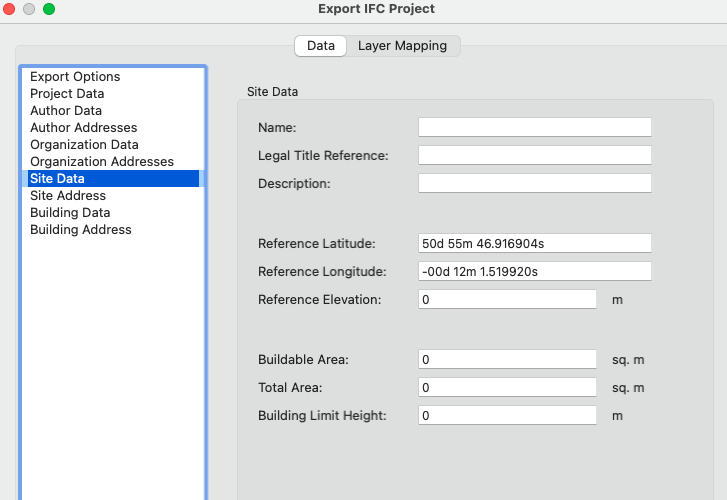
Is this where the problem lies? and how can I fix it (no way to input accurate N/E coords)?
Other consultants use Revit so I can t ask them to just import using their document coords. The IFC needs have the correct coords.
Kind regards,
Jack
-
Is there a way to have the hardscape border sit on the outside of the hardscape rather than inside the edge?
Many thanks,
Jack
-
2 hours ago, E|FA said:
If you want to use the Wall tool, you can draw the curved form in plan using the polyline mode.
https://app-help.vectorworks.net/2024/eng/VW2024_Guide/Walls/Creating_walls.htm
You can ADD and pull vertices up & down using the Edit Wall tool.
https://app-help.vectorworks.net/2024/eng/VW2024_Guide/Walls_edit/Reshaping_walls.htm
https://app-help.vectorworks.net/2024/eng/VW2024_Guide/Walls_edit/Adding_a_wall_peak.htm
Another option is to create an object that defines the top of the wall (which can be hidden or deleted later) and use the Fit Walls to Objects command.
https://app-help.vectorworks.net/2024/eng/VW2024_Guide/Walls/Fitting_walls_to_defined_geometry.htm
I will also explore the last option here. if I can set it to match the hardscape surface and offset it to the edge of the hardscape then it should be a good solution.
-
1
-
-
Was considering the wall method from @E|FA but wanted a smooth line instead of straight wall sections making a curve.
Thanks again all.
-
1
-
-
All sorted. Save your time instead of making a video.
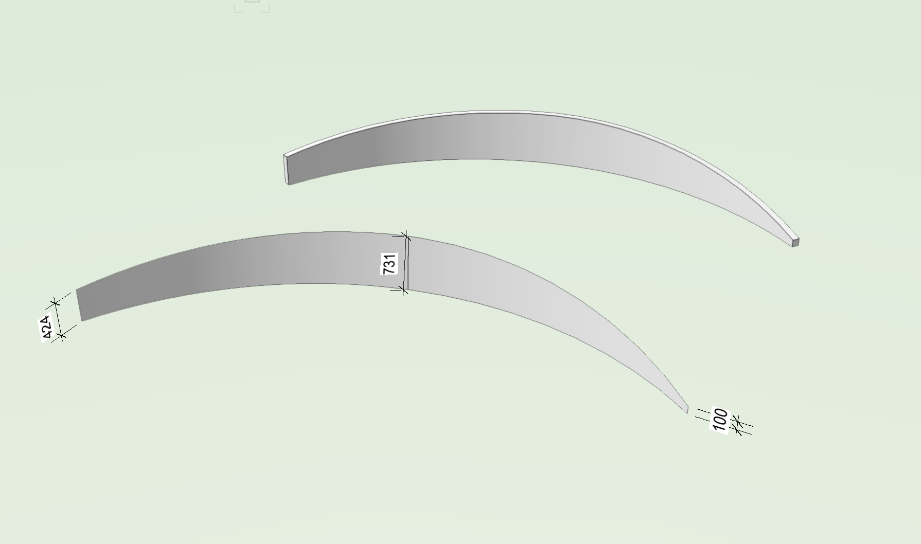
I finally got to grips with Nurbs curves and shell solids. exactly what I wanted and painless once I got a routine method and found the pitfalls.
Accurate polyline curve in plan view, convert it to nurbs, gave it a z value to locate in model, pulled nurbs curve handles in the Z axis to create the top curve. Added a bottom nurbs line and lofted the two. The loft is perfectly vertical unlike creating surface from curves command.
Then shell solid to create thickness.
Thanks all for helping isolate a solution.

-
4
-
-
That would be amazing thank you.
I feel it must be a simple thing to do considering the power of VW. Just I am struggling to find the methods.
-
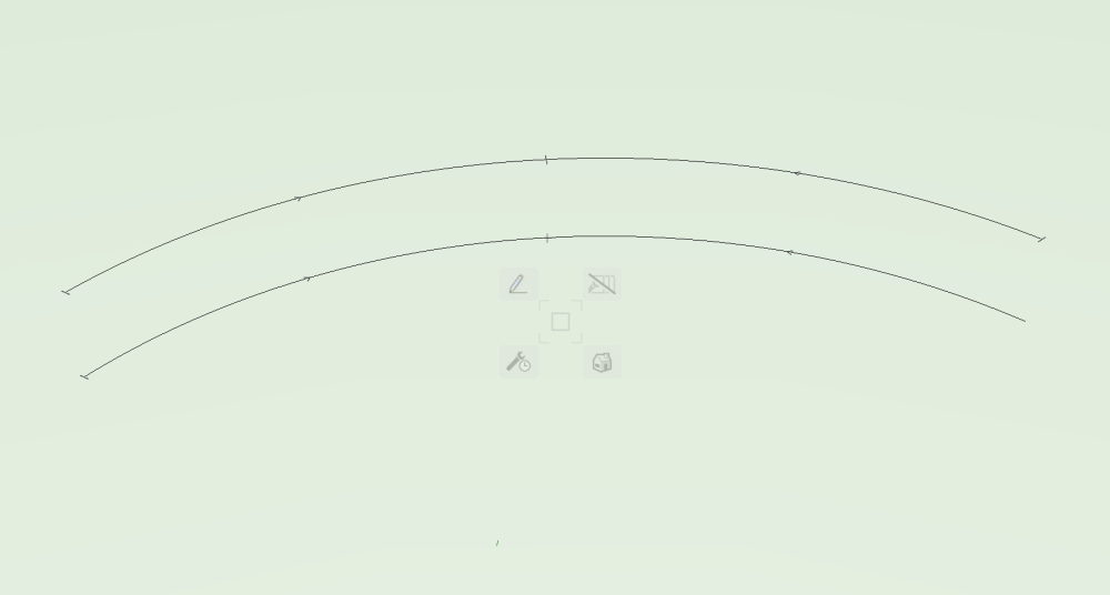
this sounds promising it doesnt let me move the end points down though?
the two curves I have drawn are 2D one above the other.
toothy need to be a particular type of curve?
honestly not that much or a rookie but this I haven't done before.


Wall Pier Tool
in Site Design
Posted
Thanks Jeff,
I had a play with the columns tool and it works well. Can add bases and caps and good control over parameters.