


alexmootv
-
Posts
30 -
Joined
-
Last visited
Content Type
Profiles
Forums
Events
Articles
Marionette
Store
Everything posted by alexmootv
-
Hi All, I am very interested in this as well. I currently have a workgroup library that contains a Vectorworks file for all of our ConnectCAD symbols. We save them here as symbols rather than using the device builder for several reasons. Since it creates the 3D Equipment Item at run time I don't quite understand the process on how to save the slot layout. What I would like to happen is that once I have edited the slot layout that I can somehow save this along with the symbol definition, or have it associated in some way on our NAS in the workgroup so that when anybody else uses the Device Symbol and clicks Create Equipment it generates the geometry with the slots as well. Any advice on workflow here? Thanks so much, Alex
-
Hi, Is there a way to assign and clear cable numbers for multiple design layers at a time? I have a drawing with 61 design layers so far and it would be really nice to be able to bulk create and clear cable numbers across the drawing set rather than having to go into each design layer. This normally comes up when I add a device after assigning cable numbers, and I want their numbers to be sequential. I then have to go to each layer one by one and clear all cable numbers and then reassign all cable numbers layer by layer. Thanks in advance, Alex
-
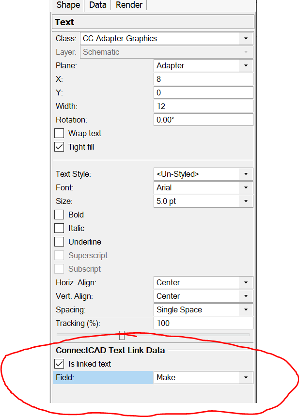
Thank you @Nikolay Zhelyazkov. This works. My confusion. So, to summarize for myself and anyone who stumbles upon this later: To create an adapter within the resource manager go to the resource manager Adapter Symbols>Default Adapter. Make a duplicate of Default Adapter. We can name it "Custom Adapter". Edit 3D component of Custom Adapter. Then double click on the adapter object nested within the symbol. Now you are editing the adapter. Use the textbox tool to drop a textbox anywhere. The ConnectCAD Text Link Data propery will be displayed in the Object Info pane. Thanks, Alex
-
Hi @Conrad Preen, Following up on this. I just tested this, and it does work as you described on an actual circuit. The rub is that once you edit the schema via text, the visual editor then shows anything after the three g's as the suffix which is unexpected behavior. So, this does solve my problem. Much appreciated. It also highlights some room for the visual editor dialog box to be polished, very minor, however. Thanks, Alex
-
Hi @Nikolay Zhelyazkov, I currently don't have the time to setup a scenario and screen record it. Maybe someday I can follow back up with this. For now, to reproduce what I am talking about, take a blank file, go to the resource manager Adapter Symbols>Default Adapter. Make a duplicate of Default Adapter. We can name it "Custom Adapter". Edit 3D component of Custom Adapter. Use the textbox tool to drop a textbox anywhere. Type in some random text so the textbox persists. While that textbox is selected, look at the Object Info pane. You will notice that ConnectCAD Text Link Data is not available to a normal textbox inside of an adapter. Thanks, Alex
-
Hi @Conrad Preen, I tried this the other day and it did not extend the number generator like I had hoped. Instead, it just added a suffix of g. Does this work on your end? Thanks, Alex
-
Hi All, I am currently using the cCAD2 cable label schema that is defaulted in ConnectCAD. However, it has one big scalability issue, in that for that schema the unique number generator appears to be limited to 3 numbers, meaning at most you could have 999 cable IDs per signal type. This is a problem for me as it does not scale for larger systems. For things like device names, I include the room number and a sequential number to help mitigate any scalability problems. i.e Server 109.1 where "Server" is the device type, 109 is the room number, and 1 is a sequential number of "Server" per room 109. For cable IDs however, I haven't come up with a good solution to allow for scalability. Ideally each ID is unique and short. I don't really need it to have socket information or device information on the cable label. All of this to ask, is there a way to increase the unique number generator size beyond 3 digits or does anybody else have a preferred schema that helps combat the scalability issues of a sequential number? Maybe a sequential number that is unique to each room of the source device? i.e N109.587 where N is the signal, 109 is the room, and 587 is a unique number within that room. This starts to break down with IO sockets on each end. Any ideas? @Conrad Preen Thanks in advance, Alex
-
Hi @CharlesD, Following up here. I did some digging and finally found where I grabbed the special textbox from that lets you bind to data from the Adapter object that is not in a record. If you navigate to C:\Program Files\Vectorworks 2023\Libraries\ConnectCAD\Adapter there is an Adapter.vwx file that has some SFP adapters in its resource manager. If you find the symbol "EB30HD2T-LN" it has a textbox in the middle of it that on first glance looks like a normal textbox except that at the bottom of the Object Info pane there is a section labeled ConnectCAD Text Link Data. If you click the "Is linked text" checkbox it then allows you to bind it to the symbol name, make, or model. Or create a custom schema. I have no idea how to give a normal textbox these properties so the only thing I know to do is to copy the textbox into other symbols and use it. While linking to records works, this is linking directly to the object data. There has to be a better way that I don't know of to do this @Conrad Preen. -Alex
-
Hi @CharlesD, I'm a bit late to the party on this. Like everyone, I've been extremely busy. Thanks for showing an example of how this works with something like an E2. I have messed with adapters in pretty much the same way you are showing. I currently don't use them for cards as I just haven't had the time to finish vetting the process and what it may impact in our workflow, such as circuit worksheets. I suspect I will move that direction eventually. One of the downsides I have found, not any fault of ConnectCAD, is the reality that large frames will always end up being large even if they aren't fully populated. While this does standardize the size of a symbol for a device, sometimes it is nice to have the ability to make the symbol smaller if it's not fully populated. Currently I am just editing the instance of a device to give it the sockets I need rather than using adapters, but it's not the most elegant and then the cards don't show up in the BOM list. I'll eventually revaluate Adapters. I need to find the time. As far as Make_Model labels at one point I stumbled upon a way to bind a text field to the name of the symbol name which made managing that process easy. However, I can no longer figure out how to do that. Maybe @Conrad Preen knows. I feel like it wasn't a standard text field linked to a record, but a special ConnectCAD text object I had copied off of something else in the system that allowed me to do that. Thanks, Alex
-
@Nikolay Zhelyazkov Thank you for your reply. I did try copying everything into a new file and this fixed the problem for a few days. As of today, the bug cropped back up again. In addition, I now also experience a bug where any connection made from 2 devices with right facing sockets that are IO type now appear with one end of the circuits text labels upside down. How can I send you the file to have a look? And is this something that is possible for you to repair the file and send back to me? Copying all of these design layers into new files is turning into a huge time sink. Thanks, Alex
-
@spettitt I wasn't meaning to take over your post with the above issue. However, I think you will find with the current state of things sometimes Vectorworks overrides what you put in the workgroup files making the grouping not always work until this is fixed. I personally liked @spettitt idea of being able to add these categories in the workgroup with a special syntax. I believe he mentioned "Lighting(tab)=(return)". This way as we add new signals to our workgroup, we can just create those headings in the file. I would love to have the ability to do what @spettitt is suggesting above, but I wouldn't want it defined by Vectorworks. This would emply Vectorworks is able to think of every edge case which is impossible. I would want to create the hierarchy in our workgroup files. I also think the protocol vs. signal type is interesting as I face this often. However, I end up just making a new signal type for anything, even if it is ethernet. I think this could open up a can of worms however going to granular. If you did choose to start diving more granular however, the 7 Layer OSI Model, might offer some guidance as to how to structure things. https://en.wikipedia.org/wiki/OSI_model Thanks, Alex
-
Hi All, I think this has similar reference to my complaint of the new behavior in the below post @Nikolay Zhelyazkov. https://forum.vectorworks.net/index.php?/topic/101459-v2023-workgroup-signals-and-connectors-not-taking-priority/ As @spettitt mentioned, we also as a company define our own signals, that in some case share the same name as the default ones. What we currently do as a workaround since Vectorworks will not display the workgroup version if it has the same name as one in the app folder is to delete those files and mark some as read only. Below is the procedure to only show what is defined in the workgroup and not the default app group versions. We do this every time we do a new install. DELETE C:\Program Files\Vectorworks 2023\Libraries\Defaults\ConnectCAD\ConnectCAD_Database SignalTypes.txt ConnectorTypes.txt Create Empty file and Mark as Read Only In some cases, we have found another area that causes a problem, but isn't consistent. We now do this out of precaution as well. Sometimes this file already exists. Delete it first and make an empty one that is read only. C:\Users\Admin\AppData\Roaming\Nemetschek\Vectorworks\2023\Libraries\Defaults\ConnectCAD\ConnectCAD_Database SignalTypes.txt None of this helps with the grouping, which I would also like to make work. What it does do is ensure that what you define in your workgroup folders are actually displayed. Hope this helps, Alex
-
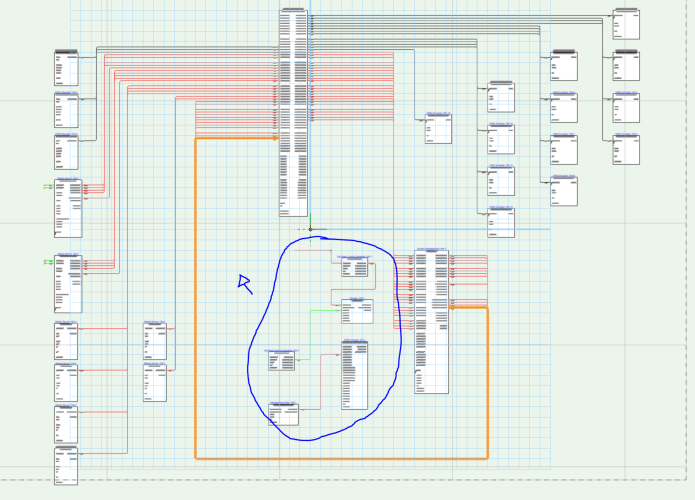
I've found a workaround of sorts, but the bug is still present. By selecting all of the circuits and from the right click menu pressing "send to back" does allow me to at least select the devices I need, but the overly large hitbox of the circuits is still present. This workaround only works, until I add a new circuit line and then the nearby devices and circuits are no longer selectable, until that new circuit is then also sent to the back. This is the only file I have exhibiting the overly large hitbox issue. By hitbox I am referring to the area used in programming for collision detection and selection of an object. https://en.wikipedia.org/wiki/Collision_detection Thanks, Alex
-
I am running into a bug where devices and circuits become unselectable, because the hit box for circuit geometry is extending well past the line. In the screenshot below you can see where my cursor is with the blue cursor I drew in after taking the screenshot. By clicking in that area, it selects the circuit line that is encapsulating the cursor. It then makes it impossible to select the nearby devices that I have circled in blue. This is happing throughout the entire drawing set to the point where I will have to scrap the entire file and start over from a new file. This Vectorworks file was a copy of another Vectorworks file that has since been expanded on. The original file does not show these symptoms, but the copied file (the one I will actually be using) does. @Conrad PreenAny ideas or workarounds? Have others experienced this? Thanks, Alex
-
Hi All, I wanted to start a discussion around the difference between rack depth and usable rack depth, in relation to the 3D view of racks in ConnectCAD. Currently, it seems that the specified rack depth is the total footprint of the rack when viewed from the top plan view. However, I most often use the 3D view to check the side isometric view of the rack for collisions of gear, airflow, and serviceability. Because of this, what I am really after is the total front rail to rear rail depth of the rack; the usable depth. Currently when I type in the rack depth in Vectorworks I add an additional 3" to the usable rack depth measurement. This allows for the 3D model to show me the correct depth from rail to rail. However, it then of course will throw off the footprint of the rack; the total rack depth. Curious if others run into this, and if @Conrad Preenand the team might be able to parametrically model this with the addition of "Usable Rack Depth". Thanks, Alex
-
Worksheet of Device Connections (Device Patch Sheet)
alexmootv replied to alexmootv's topic in ConnectCAD
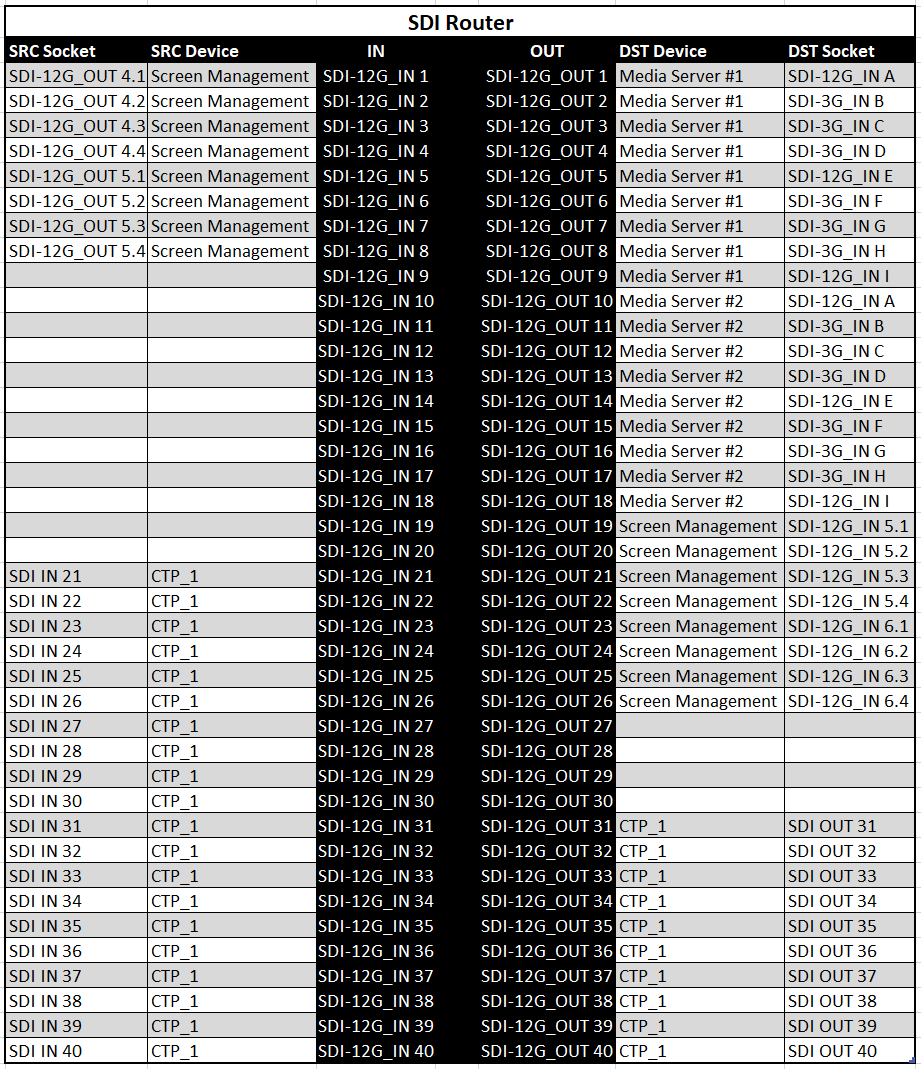
Hi @robert1, Thanks for the input. I have visited the Developer Worksheet Wiki previously and tried to do evals on the circuits, but I kept running into Vectorworks limitations. Today, I revisited the topic with some inspiration from your post and messed around with data manipulation in Excel some more. Ultimately, I was able to build mostly what I wanted from the Excel Filter function, but it's not quite the automated process I would like. I am really wanting this to live inside of Vectorworks and update as worksheets do. Short of doing VBA scripts inside of Excel there is no way for it to automatically iterate through all of my devices and build a patch table for each one. Vectorworks, would have some ability to do this as it has context of each device. The functionality just isn't there however. I have attached a screenshot of what I wish I could achieve for every device in the drawing in an automated fashion. Effectively taking the wire schematics and turning them into a table format per device. Thanks, Alex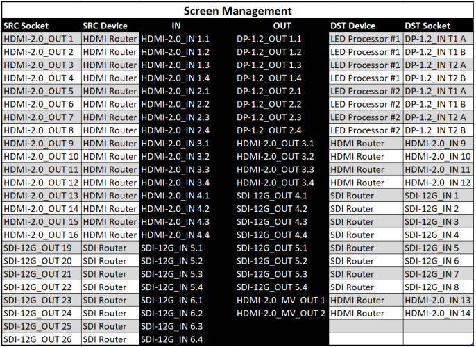
-
@Conrad Preen You just saved me many, many, hours mentioning this little nugget. I had no idea. I've been having to delete a symbol, add back the new one, rename the device, and reconnect traces on every layer I might have that device on. I did a test on this and it also carries over any added records that might be associated to the device or a socket. Is there any documentation anywhere that acts as a shortcuts handbook that has these types of useful workflows? Thanks, Alex
-
v2023 Workgroup Signals and Connectors Not Taking Priority
alexmootv replied to alexmootv's topic in ConnectCAD
Hi Conrad, Thanks for your reply. I guess what I am asking for is to just not delete my workgroup entry out of the workgroup section of the list. I understand the application folder needing to be a list you control. But, if I put an item in the workgroup I expect my entry to show up in the workgroup section of the list as well. The only other possible workaround I can think of is for us to delete the application folder file every time we install or update. This seems not ideal behavior when you could just list the workgroup entry in the workgroup section, not interfering with the application folder that you maintain at all. Thanks so much, Alex -
Hi All, I don't think I am using connector panels properly and was hoping someone could clarify. What makes since for me to define a connector panel socket as an input or output is based on if it's a signal coming into or going out of the rack. However, it seems like the opposite is true to get it to behave correctly. Say I have a connector panel that has HDMI inputs into the rack that then go to the HDMI video router. Well, this is a passthrough connector with a HDMI cable connecting them so I have to specify the connector panel socket to be an "output" in order for the circuit to get labeled as HDMI on both sides rather than "-->". It then also makes the symbol red instead of green. What about things that are "IO" like networking signals? What about non-passthrough connectors like XLR where it may be desirable to have "--" on the connector panel end, but then how do you list what type of the connector the panel itself has? Where I am really running into trouble is where I have two racks that have connector panels with cables going between those two connector panels. It doesn't let me make the connection. Any clarification here would be helpful. Thanks so much, Alex
-
Hi @Conrad Preen, Thanks for the information. I have mocked up some test drawings to play around with using adapters as modular cards for devices. It works ok, but I don't know that I am going to move our library over to that method yet. Speaking for myself, I don't need the physical view represented on the rack elevation view. It would be cool, but doesn't change my world in the least. I would love to have a way to represent the modular cards on a schematic. I mocked this up with a few devices like a Barco E2, or a Disguise media server. In these cases, I inset a socket into the device midway and then had a dashed line rectangle out to the edge of the device. This allowed me to make adapters with a "Card" socket on one side and then connections on the other. This again only worked ok. Where it becomes hard is if it's a card that is both inputs and outputs (rare, but do exist), where you would typically want these on opposite sides of the device block, rather than grouped together on the "card" adapter. I also tried doing the exact same thing, but smaller for SFPs in networks switches. I ended up choosing against this as I couldn't define a size standard across gear as some SFPs have multiple connections staggered on them. While most are a duplex LC, you can end up with ones that are dual micro-BNC for things like SMPTE 2110. I had the option to make those adapters then twice as big to hold the two sockets, but then I am making all of my network switch devices in my library many magnitudes taller just in case they need to have one of those SFPs in it. While I think the adapters are implemented well, I ended up not using them for devices in that way as I couldn't find a good way to standardize drawings for them. So currently I am not using adapters for SFPs or modular cards. We maintain our own device library in a workgroup on a NAS and then I just modify the device symbols sockets to represent the connections on the cards once imported into the working job file. Thanks for your insight and hopefully the additional information can help inform your development going forward.
-
v2023 Workgroup Signals and Connectors Not Taking Priority
alexmootv replied to alexmootv's topic in ConnectCAD
Hi @Nikolay Zhelyazkov, Thank you for your reply. It is mainly that I want them to appear in the WG category. The reason for this is that while they may, on the surface, seem the same and duplicate. They actually are not. Where this begins to differ is things like capitalization and descriptions next to the signal name. I want to standardize designers on only using the signals out of the workgroup folder as those are the only ones that I maintain. So, it definitely happens where the entry is similar by name only, but different either due to capitalization or description, but it won't then display the one in the workgroup. In addition, I would like to be able to tell designers going forward: "Only use the signal types allowed in the workgroup" as some of the signals locally defined by default, might mean the same thing, but not what the company has chosen to name them as on drawings. But I can't do that if duplicate named signals get removed from the workgroup. This way designers get a company defined list in the workgroup section of allowed signal types. I hope to see the return of duplicate entries with my workgroup listing remaining fully intact as I had defined it to be. Thanks so much, Alex -
I'm experimenting with using them for cards in modular pieces of equipment. Do these adapters assume the rack location of the host device? This mainly comes in to play for calculating cable lengths within a rack. As a developer is it your intention to have adapters used as cards in modular equipment, or should I hold off refactoring the company library of symbols to work in this way if its on the roadmap to have a Card type object or method of doing this down the road? Thanks!
-
It seems that signals and connectors defined in a workgroup do not take priority over those defined in the application folder. It used to be that if I had a signal or connector named the same in a workgroup that it is in the application folder that signal or connector would get displayed twice. Once in the application section of the list and once in the workgroup section of the list. This was important for custom descriptions and similar grouping orders within the list. Now since v2023, if there is a duplicate name it does not list it at all in the workgroup section at all for connectors and the signal dropdown menu for a Socket, mixes application folder signals in the list of Workgroup signals.
-
Thank you for the information about the new workgroup location. That worked for me! I thought this was the case. Since it previously wasn't seeing the Workgroup and signals, it was hard to tell. Thank you!
-
Same problem here. Would love to know. Do we know what file holds the color for each signal defined in the ConnectCAD settings? I would like to be able to transfer that forward as well. Thanks!


