


shorter
-
Posts
3,099 -
Joined
-
Last visited
Content Type
Profiles
Forums
Events
Articles
Marionette
Store
Posts posted by shorter
-
-
ps
Having set the SO of a double door, it would be good if the door reported the leaf size as 826, not 1652.
Or conversely, set the door to double door, and then set the leaf size of each leaf i.e. 826mm, and this sets the correct SO for a double door.
-
 1
1
-
-
Just building a content library for a few clients at the moment and have encountered the perennial complaint about the way doors work, and the fact we cannot add tolerances between door and frame.
For typical door tolerances take a look at
If we set the 7mm tolerance between frame and structural opening, the frame size is correct, but the leaf size is wrong. So if we adjust the overall frame size, and increase the tolerance between frame and SO to 10mm, the overall frame size is obviously going to be wrong.
We base our doors on leaf size.
leaf size + 2 x 3mm + frame thickness = doorset size.
doorset size + 2 x 'shim gap' as Vectorworks calls it = SO.
Without being able to specify the 3mm gap between leaf and frame something ends up being wrong in the schedule, usually the overall frame size.
I know this has been discussed before ad nauseam, but thought I would chime in again.
The problem is even worse in a double door where we need to allow a gap between door leaves in order to generate a schedule with the correct leaf size.
2 x 826mm leafs, 4mm gap at the meeting stiles, 3mm gap between door leaf and frame.
If we set leaf size to 2x826, the overall frame size is wrong if we enter the correct width and compensate in the 'shim gap in order to report the correct SO.
7mm shim gap
+
32mm frame
+
3m tol.
+
826mm leaf
+
4mm tol.
+
826mm leaf
+
3mm tol.
+
32mm frame
+
7mm shim gap
=
SO
Overall Frame size is SO - 14mm.
We have to model
12mm shim gap
+
32mm frame
+
0m tol.
+
826mm leaf
+
0mm tol.
+
826mm leaf
+
0mm tol.
+
32mm frame
+
12mm shim gap
=
SO
Overall frame size is SO - 24mm.
-
3
-
-
The current behaviour of 'paste in place' is to deliver the objects copied relative to the coordinate system defined by the user origin, or if there is no user origin, aligned to the coordinate system defined by the internal origin.
Sometimes, we want to copy from a file containing a user origin but want to paste relative to the internal origin.
An option to do this in the paste in place command would be useful.
As would 'copy with base point' where you select objects, define a point in the source file, copy, click on a point in the recipient file, and paste and the objects paste relative to the click point.
There are obviously workarounds but each is an extra step compared to the above and involves a manual move of the data after placement or a temporary cessation of the user origin, both of which we would rather avoid.
-
In a 2D workflow unified view is probably unnecessary, but would be a bit of a pain in 3D. This sounds like a bug to me.
-
Currently they sit there in the order created, rather than alphabetically.
Would nice if we could drag them up and down.
Also, when importing filters, could we import individual filters not the entire content of the file we are importing from.
-
1
-
-
I shall test as we have a lot of projects with walls inside symbols… could be a problem if this does not work as expected. I often find that some plugin objects do not update very readily when inside a symbol.
-
Which version of VW is this?
-
3 hours ago, Helm said:
If you are in the EU you can still buy a perpetual license until I think September.
Is this true? Of course the UK is stupidly not in the EU any more, but I thought the deadline for new perpetual licenses was 31 December 2023, and that Service Select is no longer available because it can only be purchased with a perpetual license unless you are currently a service select customer and looking forward to your renewal.
-
It should be like a roof plane.
If you look at a ramp in section, it generally has constant thickness, like a roof finish.
So, if the ramp could be like a roof we could 'style' them.
We use the roof plane at the moment, but have to then draw the ramp arrow, which is a bit of a pain, but it's constructionally correct and if I am not mistaken, on a BIM project, that's the name of the game.
-
1
-
-
The frustrating thing is that non-compliance in vectorworks is far easier than compliance!
-
Could this be a document setting rather than an application setting? It currently resides in the application preferences.
-
I am talking about the classification fields that are standard in every standard ifc pset. I am not talking about a new pset.
for example, the Wall has Cost Index fields that map to the Classification Name and Classification Reference fields in the ifc attributes of the wall, eg Uniclass2015 Ss_25_10.
if I enter XX-YYY in place of Uniclass2015 it does not export. XX/YYY does.
The issue is that we have been told to use the hyphen and I am not sure the hyphen is a permitted character in that field or if it’s a vw bug.
-
There is a desire to report the volume of PPC for the purposes of Embodied carbon calculations…
-
1
-
-
Circular Hollow Sections
-
Polyester Powder Coating…
I have of course suggested a homogenised approach as per galvanised steel but they would like to differentiate the steel from the finish.
-
It does not appear that we can enter percentages of material to any greater accuracy than 2 decimal places.
If I have two materials in the proportion 99.999999% and 0.000001% it rounds to 100.00% and 0.00% but strangely does show one of the materials as having a volume of 0.00001m3 on a 10m x 10m x 10m volume but shows the other material as being 1000m3, and not 999.99999m3.
-
Apologies if I have posted this already.
If I enter XX/YYY as a classification name in the ifc classification pset, I get XX/YYY listed as classification in the IFC when viewed in Solibri or BIM Collab.
If I enter XX-YYY, I get nothing.
Is this a Vectorworks bug or IFC semantics?
-
I am sure materials is not the only place where a lookup of the correct classification would be useful.
When creating content, it would be great, for example, to have a lookup in the Wall Data Cost Index fields, or the Classification field in the IFC property set, or when mapping classes, or in the Data Manager....
-
Here is a very simple example of what I am looking for with the Trim Tool.
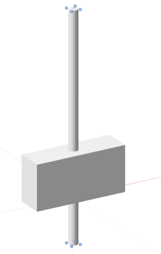
I would like to simply use the Trim Tool to remove the lower section of the cylinder that hangs below the rectangular geometry.
I would like to do this with one click. I would like to not have to select anything. I would like to not have to create another object. I would like to not have to go into another view to use the split tool.
If these were 2D objects, I would simply select the trim tool and it would trim the 2d object to the nearest object.
Not so in 3D.
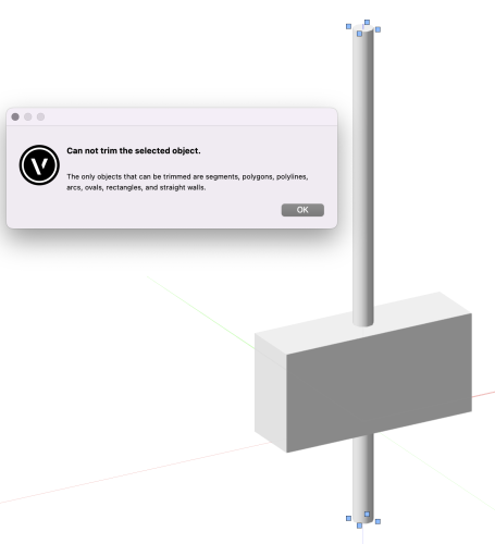
Yes, I know there are other tools that would do this but what I wish for is the Trim Tool to do this with greater ease and efficiency.
Trim Tool will throw up an error...
-
1
-
-
Dear Vectorworks
Would it be possible to issue up-to-date Uniclass 2015 classification tables with every service pack in future?
Table Pr for example was updated in April 2023, and is now on revision 1-30. The version that ships with VW is v1-19.
For those interested, the csv that works with the lookup classification tables in the materials properties dialog can be found here
https://www.dropbox.com/t/195w5kmiIoYa4A2Q
I have saved it as a Dropbox link because I cannot upload csv files to the forum.
Save it in the Libraries/Defaults/Classifications folder in the application folder or workgroup folder.
Note to Vectorworks... These tables now include a 'Sub-Object' column and this throws Vectorworks off the scent, and the descriptions that we rely on to find the correct code are missing. The csv above has the sub-object column deleted.
Thanks.
-
1
-
-
The split tool only works in one plane. Which is fine in this instance, and that's what we used, but when another 3D object meets a more complex geometry...
-
The columns need to remain as individual columns.
I suppose it was semantics. The command says ‘subtract solids’ but doesn’t. It only subtracts one solid from another.
the split tool only works in one direction and would not help if the wall, for example, undulated.
Section Solids works once the geometry is aligned correctly but was overlooked.
-
Some fiddling and indeed the Section Solids command will do what you want but requires specific relationship and does not trim the solid to each other with is another option we need.
So, request stands... The 'Subtract Solids' (plural) command should do as it says and subtract multiple solids!
-
Split tool only works in one plane, which is fine, and only along a single line, i.e. it has no polygon mode.
Section Solids does something very strange... It does not cut all solids in the same way and they all have to be modelled such that there is no geometry below the trimming geometry otherwise like the subtract solid command, you get what looks like two solids but they are joined.


Architectural Fees - how to get more $$ upfront?
in Architecture
Posted
@jeff prince I must admit I thought the question was from a recently qualified architect not one of 40 years practice. Not sure it warranted that response.