
shorter
-
Posts
3,085 -
Joined
-
Last visited
Content Type
Profiles
Forums
Events
Articles
Marionette
Store
Everything posted by shorter
-
I suppose what you suggest @jeff prince just isn’t very clear when compared to the internal origin marker. It is clearly an issue that the majority are unaware of even when they have a user origin in their file so some clarity would not go amiss.
-
No. It was an answer as to why I would rather a proper icon rather than something that most people turn off because they find it annoying.
-
My feeling is that if you can see both internal and user origins simultaneously in top/plan you might start to comprehend what’s happening and what the relationship is between the two points. it was not until Revit got an internal origin marker that Revit users started talking about it. It was all project base point this and project base point that but in truth no one knew what they were doing with it and kept on moving it resulting in a total arbitrary coordinate at the internal origin.
-
Unfortunately not as you stray outside that 5k limit on every project if you only ever set one user origin, don’t you?
-
Don’t use printer page sizes if you want to fix that. Set up true full bleed page sizes in the printer setup
-
Because it only works in 3D?
-
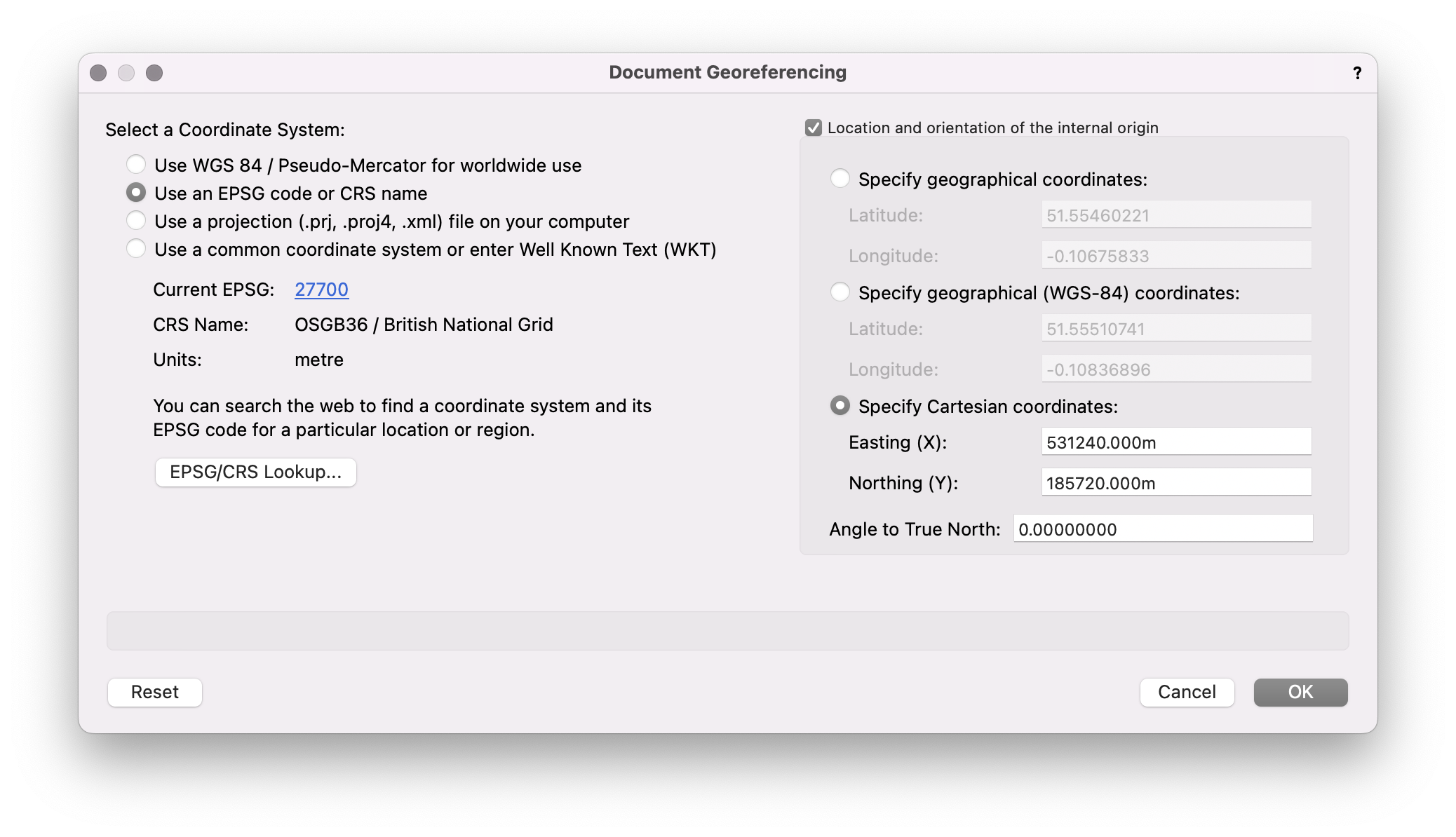
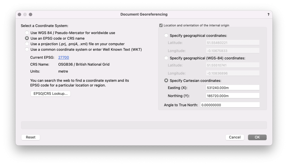
@Tom W. of course and we do hence the presence of a user origin but we turn it on and off. It is only on when exporting or for setting out otherwise we have found certain objects do not like being in OS coordinates and rotated view at the same time. Models are more reliable when linked via the internal origin too. I think since there does not appear to be any clear guidance on this I will offer the following, as far as they relate to architecture: 1 all models in all softwares should be set out about a common internal origin located to the bottom left hand corner of the site or in the middle of the site boundary on a larger project 2 the internal origin should be ‘geo-located’ ideally using eastings and Northings ie Cartesian coordinates according to the local site Coordinate system eg U.K. OS coordinates. 3 The coordinate defined at the internal origin should accurate to the nearest site unit and not rounded ie the nearest metre but ideally to the nearest 10m. eg 531240m 185720m 4 longitude and latitude should be set to the Cartesian coordinate above using a suitable conversion tool if not in-built into the software like vectorworks 2023 😉 5 longitude and latitude accurate to 8 decimal places are sufficient to establish 1mm accuracy on the ground which is generally sufficient given the distance if the sun to the surface of the earth… 😉 6 models should be set out true north 7 rotation angles used to define rotated views to work orthogonally to the screen (aka ‘project north’) should be accurate to max. 4 decimal places and not rounded. (This does require a leap of faith as many treat their surveys as being minutely accurate whereas they are probably +_ 50mm tops) 8 Common levels should be established across all models. A decision should be made as early as possible whether models will be built in true height AOD or relative to a datum such that ground floor FFL = 0m, which in turn relates to 100m AOD. 9 Carry out proof of concept test and view results in a non-proprietary viewer such as Solibri. Discuss.
-
Ps apologies, i clearly digress from the subject of my own thread!
-
It is interesting that the thing that is singularly missing in current documentation is how we actually coordinate our models in the first place! For example... where is 'origin' or 'coordinate system' in this lot? https://www.thenbs.com/periodic-table-of-bim Have we lost sight of one of the basic principles of coordination and think coordination will happen without trying as long as one names one's files correctly? The origin is the most critical point in a model. Fullstop! Where it is in relation to the world is important but it is secondary to where it needs to be if you are to share models effectively. And to share models effectively you all have to establish the same coordinate at the same point in the model. And that coordinate needs to be written down and recorded in the BEP. It is far easier to tell someone using revit or vectorworks to set their internal origin to 531240m , 185720m, than 531238.34567284923625131526374...e08m, etc. And conversely establishing the coordinate system in Vectorworks is easier if you set the User Origin, either via the User Origin command or now via Geo-referencing, and let the longitude and latitude follow, not the other way round which will invariably end up with user origins accurate to a million decimal places and which no-one can write down precisely because software has a tendency to round things. Our User Origin is very different to yours. The coordinate varies project to project since we set this to the coordinate that is defined in the BEP and this of course varies per project. This ensures that the internal origin in VW matches the IO in RVT, etc. That way we are always working within sniffing distance of the site, and we can work in local or global coordinates.

-
Georeferenced using Latitude and Longitude?
-
I am guessing, and it is a wild guess ;-), that you used the recommend 'centred on import' setting when importing the original DWG?
-
Cmd 9... What does it say?
-
And your user origin is somewhere remote to the bottom left hand corner of the site, and somewhere sensible to the nearest 10m? We still get user of another software get their Eastings and Northings the wrong way around, which is quite disturbing when it's the surveyor...
-
You mean you work in true OS coordinates all the time, up to 970km away from the internal origin!?
-
@abirolfs ...and then add data to it via the ifc property sets, or add your own data. Not everything in BIM is parametric, and arguably something that is built shouldn't be parametric, i.e. it shouldn't change from what is built. You add data to something as simple as an extrusion in Vectorworks quite easily. In general, when a standard BIM tool does not exist (and they are notoriously limited in all software out of the box) you model it. Whether that's creating a simple solid model, or placing that inside a symbol as @jeff prince suggests, or even trying to use the stair tool to achieve the same, you will need to model it yourself or download the 3D model ideally as IFC that the manufacturer had already modelled and include it in your model. If this were Revit we would be going to great lengths to model a bespoke family, whereas in Vectorworks you simply 'model in place'.
-
The internal origin is blue and has a definitive icon. The user origin should be likewise but red, IMHO. I suppose it's more about consistency which even Revit has been able to do in this respect. When you are in a 2D view it needs to be a lot clearer since this is where you set the user origin.
-
User Origins are quite simple when you don't use them, or when you do, you have a strategy for why a file has one or does not. You must always be in control of where it is, or more specifically and more importantly where your user origin is in relation to the site. The biggest issue is that 90% of issues with user origins is because one was created without knowing why or how it got there.
-
We respectfully request that the ubiquitous user origin is made visible in the same way the internal origin is made visible via Display Preferences, perhaps in red, as opposed to blue if for no other reason than to make users aware that they have a user origin. The current yellow indicator where the rulers meet is useful but does not show you where the new coordinate 0,0 is as a consequence of a user origin shift, either deliberate or otherwise. It might make users more aware of the impact of using 'centre on import' when importing DWGs where Vectorworks moves the user origin to a completely arbitrary location. Thank you.
-
Oh and as one of my clients often quotes ‘build it minimally’…
-
in a word… practice! oh, and patience oh, and care… like cameras models never lie. takes 3-4 projects before you get it close to how you would have drawn it (unless you are like some users of another software that shall remain nameless who simply do not seem to care). this is why for very good reason they say never wait until you biggest project to ‘do bim’. I would add to that never wait to be told. bim under duress results in the same result as does bim without a plan where you have no strategy as to how you are going to model.
-

Architectural Fees - how to get more $$ upfront?
shorter replied to Shortnort's topic in Architecture
Tend to find clients are happy to pay (more) when they can see they are getting a quality service. I don’t think BIM has anything to do with it. bIM is just another way of getting your work done. If anything they will be expecting a discount because they have probably heard things can be done faster so be careful what you wish for! -
Architectural Fees - how to get more $$ upfront?
shorter replied to Shortnort's topic in Architecture
@jeff prince I must admit I thought the question was from a recently qualified architect not one of 40 years practice. Not sure it warranted that response. -
Door Dimensions and Tolerances
shorter replied to shorter's question in Wishlist - Feature and Content Requests
ps Having set the SO of a double door, it would be good if the door reported the leaf size as 826, not 1652. Or conversely, set the door to double door, and then set the leaf size of each leaf i.e. 826mm, and this sets the correct SO for a double door.- 1 reply
-
- 1
-

-
Just building a content library for a few clients at the moment and have encountered the perennial complaint about the way doors work, and the fact we cannot add tolerances between door and frame. For typical door tolerances take a look at http://www.leaderflushshapland.co.uk/Integrated-doorsets/Technical-Resources/Technical-Guide/Design-Considerations/Tolerances-Dimensioning If we set the 7mm tolerance between frame and structural opening, the frame size is correct, but the leaf size is wrong. So if we adjust the overall frame size, and increase the tolerance between frame and SO to 10mm, the overall frame size is obviously going to be wrong. We base our doors on leaf size. leaf size + 2 x 3mm + frame thickness = doorset size. doorset size + 2 x 'shim gap' as Vectorworks calls it = SO. Without being able to specify the 3mm gap between leaf and frame something ends up being wrong in the schedule, usually the overall frame size. I know this has been discussed before ad nauseam, but thought I would chime in again. The problem is even worse in a double door where we need to allow a gap between door leaves in order to generate a schedule with the correct leaf size. 2 x 826mm leafs, 4mm gap at the meeting stiles, 3mm gap between door leaf and frame. If we set leaf size to 2x826, the overall frame size is wrong if we enter the correct width and compensate in the 'shim gap in order to report the correct SO. 7mm shim gap + 32mm frame + 3m tol. + 826mm leaf + 4mm tol. + 826mm leaf + 3mm tol. + 32mm frame + 7mm shim gap = SO Overall Frame size is SO - 14mm. We have to model 12mm shim gap + 32mm frame + 0m tol. + 826mm leaf + 0mm tol. + 826mm leaf + 0mm tol. + 32mm frame + 12mm shim gap = SO Overall frame size is SO - 24mm.
- 1 reply
-
- 3
-
-
The current behaviour of 'paste in place' is to deliver the objects copied relative to the coordinate system defined by the user origin, or if there is no user origin, aligned to the coordinate system defined by the internal origin. Sometimes, we want to copy from a file containing a user origin but want to paste relative to the internal origin. An option to do this in the paste in place command would be useful. As would 'copy with base point' where you select objects, define a point in the source file, copy, click on a point in the recipient file, and paste and the objects paste relative to the click point. There are obviously workarounds but each is an extra step compared to the above and involves a manual move of the data after placement or a temporary cessation of the user origin, both of which we would rather avoid.