


Megan M
-
Posts
10 -
Joined
-
Last visited
Content Type
Profiles
Forums
Events
Articles
Marionette
Store
Posts posted by Megan M
-
-
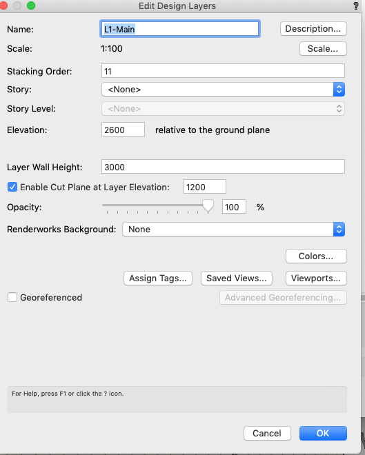
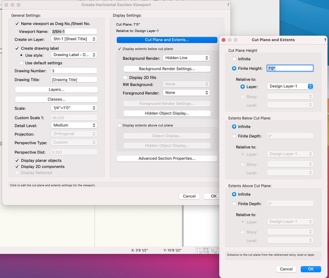
On 3/20/2022 at 8:31 AM, Pat Stanford said:
There is no way to adjust the Cut height of Top/Plan view.
Try Create Horizontal Cut Section Viewport and set the Cut Plane height of that.
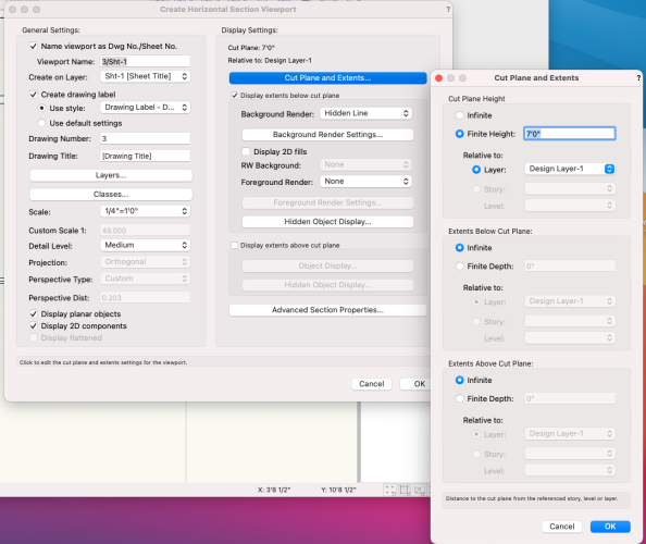
I thought you could go into the design layer properties and Enable Cut Plane Elevation for that layer, and then create a viewport for a sheet layer. However, I've tried this recently , to prevent overhead my wall cabinets from showing up on a kitchen plan and it hasn't worked. Is this feature used for something else?
-
 1
1
-
-
Hi Nikolay,
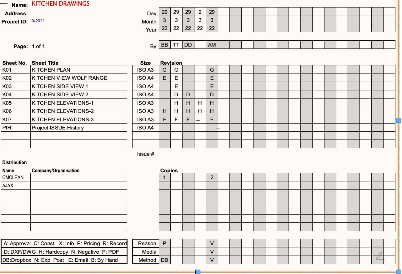
I'm not sure what you mean about the drawback - on the PRH sheet, the Issue order has the most recent on the right, and the copies follow this in columns below.
I don't know why the text kept clearing - I wasn't actually updating, it was just disappearing each time I added a new issue. I think it might have had something to do with amendments I made to the Project Revision worksheet?, I deleted several blank rows for the sheets as I only had 10 drawings, I also deleted several rows of the distribution table.Is there a certain way this should be done?
After playing around with no success, I deleted both the PRH and PIH worksheets from the resource manager and re-created them again through the Title Block Manager. I didnt try deleting any rows or making any adjustments to the tables in the worksheet. This seems to have fixed the problem of disappearing text.
Thanks for your help.
-
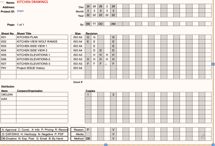
This is an example of a test worksheet I am playing around with . I am using the Project Revision History worksheet and see that there are is a "Distribution" table and fields for "name" "company" and "copies" are these fields automatically filled in some way, or are they intended to be used manually?
So far I have tried to use them manually, however when a new revision is added, I loose the "names" and "copies" (the fields go blank) which I would normally expect to stay as a record of which revision has been sent to each person.
Thanks in advance for any thoughts on this.
-
Great thanks I will try these suggestions!
-
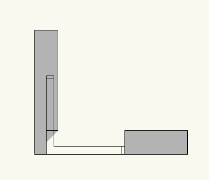
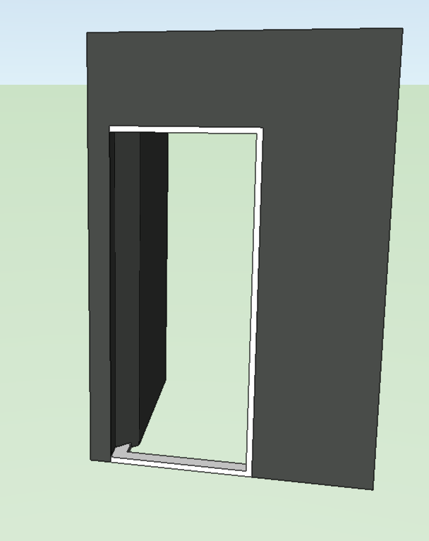
After reading this advice, I have created a corner window symbol and have inserted in the wall, however, VW does not recognise the corner as one wall, so have ended up with this situation - was wondering if there are any suggestions on how to do this - should I look at creating a seperate cutout symbol for the other wall or is there something I have missed in making the walls continuous?
-
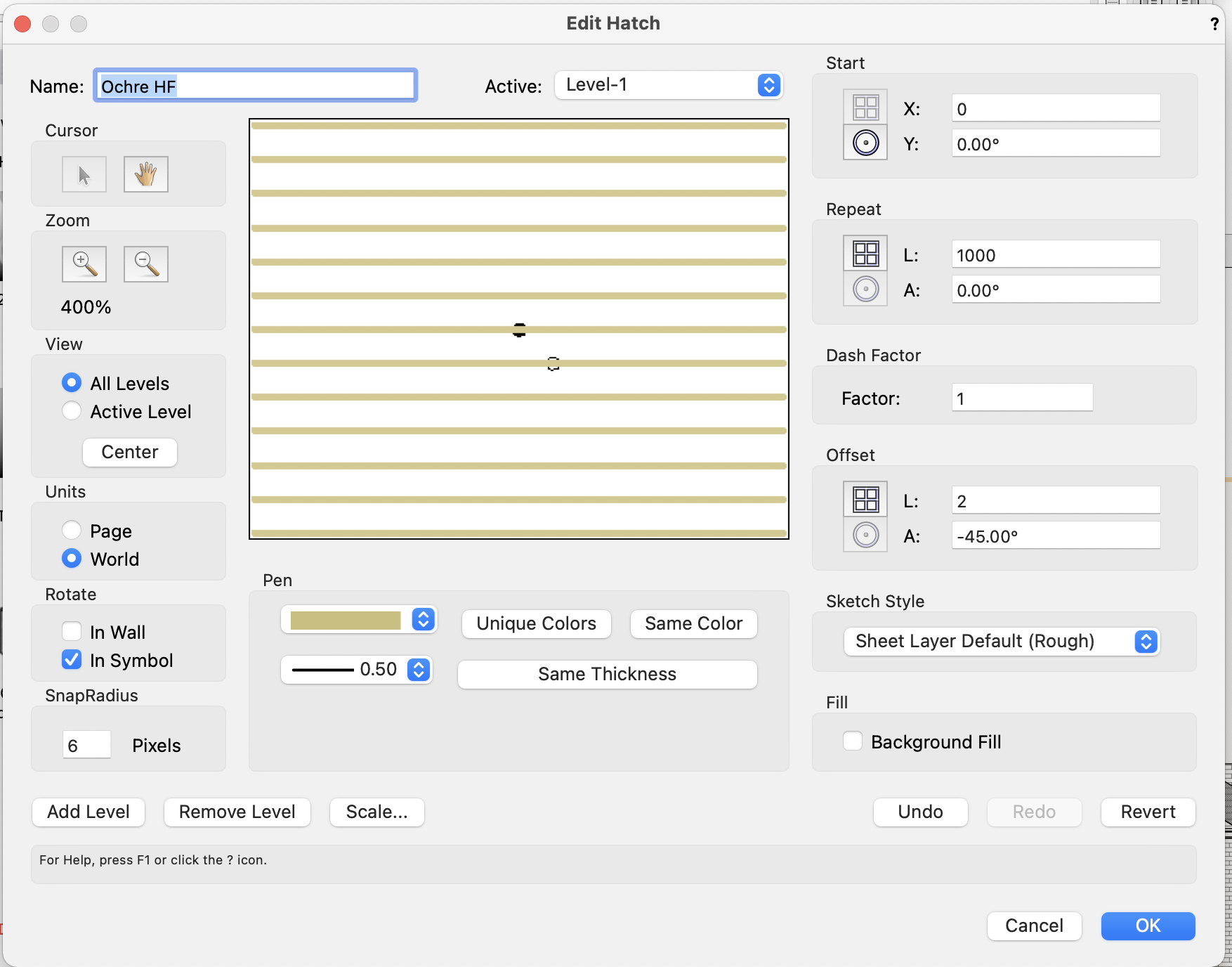
On 1/22/2022 at 5:58 PM, Tom W. said:
Ha ha but you got me wondering. Would such a hatch actually be an issue? Compared to some of the other hatches out there e.g. stone hatches with 798 levels...? My hatch is very simple in comparison:
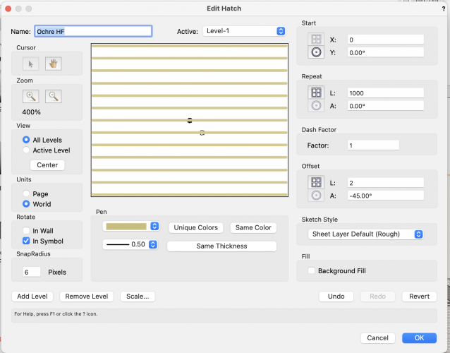
I tried that too, before moving onto doing it with the line. I guess Hidden Line literally just does lines...? And for that reason I don't think Data Viz will work. Data Viz will allow you to swap the texture displayed on an object to a different one but that won't change the fact that Hidden Line won't support the display of a solid fill colour. You could use it to swap the surface hatch displayed but would still need to use a thick coloured line hatch like above to have it look solid...
I tried this and it worked well for what I needed - simple building elevations at 1:100 scale for local a authority approval
-
Yes that is the answer- I have turned off WD-Ceiling class - thankyou!
-
1
-
-
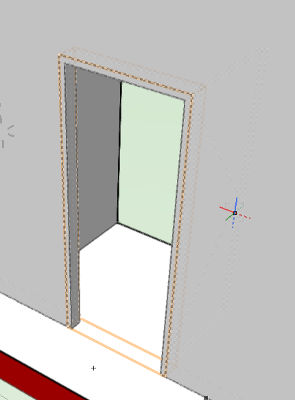
I have No Sill and 2D: None selected,. The door is a single hinged door in an internal brick wall
-
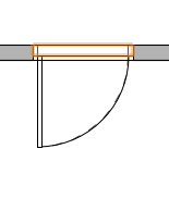
I have a similar question to this, however its the opposite problem -I cant get rid of my door sill - I have a standard door in a wall and even though there is no sill showing in 3D, there are still 2 lines (which correspond to wall line) showing on the top/plan view.
I have selected "no threshhold" in Form and the preview shows the top/plan view with no lines. I have also selected "no sill" in settings and put the detail level to "low" in the detail settings.
Am I missing a step here?
WINDOOR OBJECTS AND CLEAR GLASS
in Architecture
Posted
I have a 3D model using a clear glass texture in the windoor objects so my clients can see through the windows in the 3d open GL views I present.
However, when I create the elevations of the building , I don't want the windows to be transparent as you can see the lines of internal walls. Is there any way to address this?
The only way I have been able to get around it so far is to change all the windows to opaque for the elevations and then change back for the 3D views.