Will M
-
Posts
19 -
Joined
-
Last visited
Content Type
Profiles
Forums
Events
Articles
Marionette
Store
Everything posted by Will M
-
Extracting Plant Counts from Landscape Areas in Worksheets
Will M replied to Will M's topic in Site Design
I've almost been able to get it sorted by starting with the Landscape Area - Mass Planting default worksheet. I can't quite discern how my worksheet differed from the default, but point being it's pulling plant quantities except for one issue: since I'm showing subpart types, I can't associate the subpart with the landscape area's attributes in the worksheet, especially if I'm using a data visualization. This is an issue because I'd like to harvest plant counts and show the symbol to be the appearance of the landscape area, not a 2D plant symbol. I have attached a screenshot of one of our Land F/X-created schedules to show what I'm trying to do in Vectorworks. Ideally the landscape areas are in color in the design layer to make them more easily distinguishable, then for viewports on sheet layers I have created a data vis to convert them to black and white hatches. Is what I'm trying to achieve possible?
-
As the title says, I'd like to create a plant schedule showing quantities (count) by individual plant extracted from landscape areas. These landscape areas only specify one plant species because I'm documenting the planting areas by defining drifts, so I have a lot of individual landscape areas. It was very easy to extract what I want via data tags for plant annotations, but while I can extract individual plant IDs in a worksheet, the plant record quantity is returning square feet instead of counts. My goal is to document the number of plants in each drift in the annotations (in this instance it's just 1 plant species), then provide a total count (sum) of each species in the schedule on the sheet. Any thoughts? Screenshots attached.data tag and landscape area screenshot.pdfplant worksheet screenshot.pdf As for things I've tried, since I only have 1 plant type in each landscape area I've tried calling for simply the total number of plants using the LA parameters, but I seem to run into issues with that since I'm looking at subparts so I can harvest other info such as the plant ID. Not sure if I've ultimately simply found a bug. I'm also open to other methods of drafting and documenting planting drifts if there's a cleaner way.
-
3D Plants for Landscape Areas - controlling visibility
Will M replied to AMPG's topic in Site Design
Unless someone else has additional insight, unfortunately I think the way you'd be coached to manage this is how you describe it: via classes within the 3D component. I have likewise had issues where I hide 2D appearance for landscape areas, but all the individual plant symbols export as blocks to DWG when I send basefiles to consultants. I'm still trying to work on effectively managing that but don't want to detract from your topic. 🙂 Overall I'd say managing plant appearances is pretty overwhelming between landscape areas, 2D components, class overrides, 3D components, Laubwerk geometry, etc... The level of control is great but it's a lot to handle and maintain standards for. -
Worked like a charm! Thanks for taking the time to dive into this Jeff. This tip will definitely make it into our firm's SOPs. I'll have to double check the export settings in ArcGIS, but knowing it's an easy fix from within Vectorworks is great.
-
Thanks for looking at this. I had noticed the ratio between the new Z value and Elevation value but didn't connect the dots in terms of unit conversion. I don't actually want my georef to be metric, there were just several options for my zone and I should have paid closer attention. With regards to the multiplier, I tried that method before coming to the forums and I was dissatisfied with the rounding error. So, I tested two things. One was to convert the georeferencing within the current document, then re-import and modify by record. Same result as before. The second thing was to open a fresh document, establish georeferencing with a system using US foot, then importing and modifying by record. Same result. What's confusing to me is that the X, Y is lined up perfectly, but the calculated Z value has an error. I was hoping you nailed down the issue but it appears something else is going on. EDIT: I tested modify by record in another file I'm working with, same state but different state plane zone. It worked perfectly. I copied the WKT into my test import file and tried the workflow again. The same WKT in the new file did not work.
-
DM'd a copy since the file needs to stay private. Will post solution here. Thanks Jeff.
-
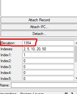
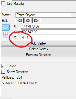
I will add to this topic instead of creating a new one for now - I'm currently having issues with Modify by Record with this workflow. Check out the screenshots for what I think is an odd result. These imported as 3D polys with 0 elevation. I tried importing as 2D polygons/polylines to modify by record, same result. Document units are in feet and I've verified scaling/geolocation is correct. If I set Z value manually, it works but I don't have the time to do that with these 1ft contours.


-
This did the trick! Thank you. Is there somewhere I can read more about the use of Object Function vs Parameter? I had been looking for a more generic data tag that can add name labels regardless of the object type. Object Function looks to be suited to that.
-
Thanks Jeff. This is almost perfect. Our standard abbreviation is SF; can I set it up to use that instead of sq ft? I tried making some adjustments without luck. And for my future understanding: Does the 0 maintain the document units, and 1 specify the precision? I wish I could do this with the drop down but I'm locked out per my first screenshot. It looks like for some reason you can freely edit those in the dialog.
-
Thanks E|FA. That link does provide a little bit more I can forward on to the surveyor so they understand my needs better. Jeff, this is certainly the tool I hope to use. Originally I was really pulling for a solution where I could quickly get loci I could convert to existing trees. After double checking my .dwg import settings, Points should be coming in as loci. I'm confused as to why Survey Points don't come in as loci, unless Points does not refer to the specific Survey Point object type in Civil3D. Again, it would be so much easier if these Survey Point objects were imported as loci or if there is some way to do that. As to the surface question, we pretty much always have a TINN from survey and/or civil. For now, that is our preferred 3D source data. When we use consulting civils instead of in-house, they will typically still own the terrain model which is one reason why. But our in-house Civils are grading in Civil3D regardless, so that needs to be negotiated. How we swap updated TINNs in throughout the project, not sure yet. Still figuring it all out--I really don't have a good understanding of how other Landmark users coordinate the site model with civils, because right now it seems like a tough task.
-
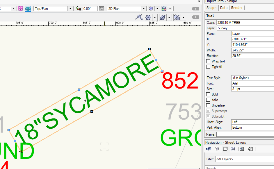
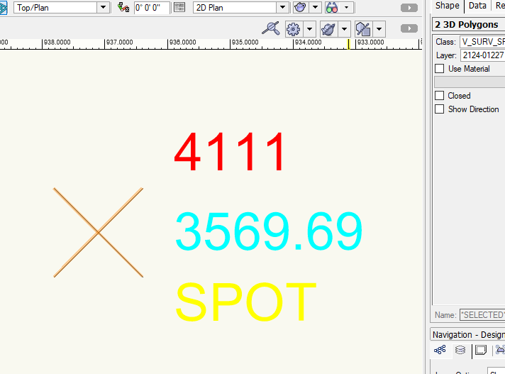
Hello, Our surveyor has provided a .dwg that I've imported, but the existing trees are done with survey points in Civil3D, which have symbols when viewed natively in Civil3D/AutoCAD. When I import to Vectorworks, I only get a text object with zero data attached to it. No symbol in Vectorworks as shown below. I think the insertion point of the text reflects the actual coordinate for the existing tree. But I would like to import these as Loci with records or somehow utilize these text boxes so I can easily create existing trees (there are 165 of them on this project) for all the benefits Existing Tree objects provide. If the only alternative is to request a tabular data set to use the Import Tree Survey Tool, what do I need to request from the surveyor? As supplemental information, I've had this issue with another survey (different firm) which did spot elevations with survey points. But the "point" comes in as two 3D polygons in VW, which is results in inaccuracies if used as source data for the site model. The issue I have seems to be with these survey points, and my wish would be that survey points are imported as 2D or 3D loci. Thanks!
-
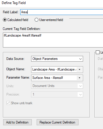
This is working for me in the sense that data tag precision reflects the document unit settings, but if I'm indicating a square footage of a landscape area this precision is not needed for the tag. That being said, I want a higher level of precision for drafting. Following this example, when I try to edit the precision of the Landscape Area surface area Tag Field (per other things I've read on the forum), I can't. From other reading it looks like I need to change the Data Tag units to something other than document units in order to adjust the precision, but you can see what I encounter below. Any thoughts?
-
I'm currently of aware of two ways to import IFC building geometry: direct import of the IFC as a reference importing the IFC into another Vectorworks file, then creating a design layer viewport for the Vectorworks file containing the IFC The advantage of #2 seems to be that I can easily go in and edit the appearance of the IFC - making sure the glazing has an appropriate glass texture and adding other materials or colors for renderings for example. To do this, I'm following Tod McCurdy's workflow from the "When it has to be BIM" webinar where he drills down and edits the appearance of 3D symbols by adding a texture. Option #1 is more convenient in my mind, but other than editing the imported classes I don't seem to have much ability to adjust the rendered appearance of an IFC. Am I wrong about that? Is option #2 the preferred way to go for this? And, most importantly, if I have to update the reference, does it undo the work I did to adjust the appearance? Thanks!
-
Finally back... some things came up per usual. Thanks for this suggestion. In this case, there was a lot of trail linework located well within the site model but I have read of this issue before. The solution I came up with doesn't feel optimal, but it will work as a base for our aerial perspective rendering (which is going into Twinmotion). Here's what I did: For the 2D trail linework that wasn't translating well as a site modifier, instead of redrawing or correcting the vertices with Reshape (sometimes there were thousands because of the import from AutoCAD), I closed the linework manually and used the inner boundary tool to generate a new polygon. There were still a lot of vertices, but it seemed to fix most overlap issues and near-perfectly replicated the geometry of the paths. The new geometry created a texture bed with no visual issues. Some texture beds (typically long trail segments) still didn't work after performing the above step. At that point, I broke the long segments into several polygons before converting them to a site modifier. Once it was broken up into pieces the site modifier applied properly for each. When it is rendered natively within Vectorworks or translated to Twinmotion, it displays seamlessly. Since this is a conceptual rendering at the master plan phase and we doubt we'll move into SDs or CDs for some time, we were fine with this approach. This may not be suitable for others trying to use the same geometry for visualization and documentation.
-
Thanks Benson. The paths were drafted in CAD as a proposed condition so I need to keep it pretty close. With that all that being said, there were lots of tiny segments to deal with so I probably missed some in my initial cleanup. Someone may have used the spline command in CAD at some point which we try to avoid... Fortunately by now I have identified some focus areas where this problem may be occurring. I will come back to this tomorrow and see if simplifying the number of segments and vertices does the trick. Could you explain a bit more about the purge tool? Basically I've been looking for an equivalent to AutoCAD's Overkill, and what I've read about the Purge tool makes it seem like it's for unused drawing elements rather than for something like overlapping geometry.
-
I'm trying to quickly use texture beds to get a trail roughly draped onto a 77acre site for an aerial perspective. The linework to create the geometry was imported from a Civil 3D .dwg but I cleaned up and closed the polygons. They are 2D with no elevation. After converting the polygon to a texture bed, the linework drapes onto the site model properly but updating the site model sometimes results in changing the texture of the whole site model. Some segments of the trail work just fine, but longer segments tend to have issues. I'm in Vectorworks 2022. Any thoughts? Will
-
That was the issue. Thank you. I should have gotten that clue last night when I was testing pads and it didn't work until I put the pad on the same layer as the site model. I did not realize this was a setting. Much appreciated.
-
Thanks Tom. I had Site Modifier Top selected for this object. I made sure the calculations for the object were updated and also updated the site model. The site model view settings for both 3D and 2D are set to Proposed Only. I tried moving the hardscape object around, and the site model would not register that there were any changes ('Update' turning red to flag that it needs updating). It feels like the site model is not recognizing this object as a modifier for some reason. Any thoughts there?
-
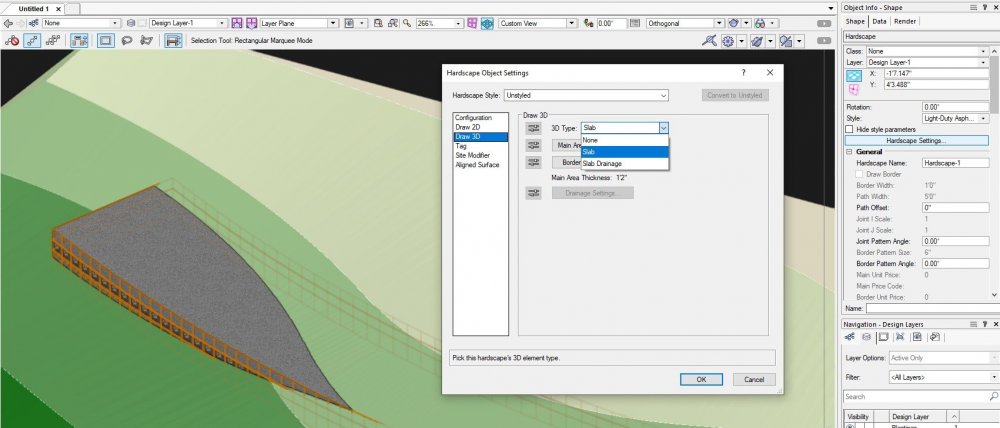
Hello, I've been messing around trying to get more fluent with Vectorworks 2022. I'm new to Vectorworks in general. I want a hypothetical walk, currently set as a Hardscape Object, to function as a site modifier. The way I understand to do this is to change the Draw 3D type to Slab Modifier or Aligned Slab Modifier, but those options are not in the dropdown menu in Hardscape Object Settings. All tutorials I've found deal with older versions of Vectorworks and show more Draw 3D types than what I have, but I don't know if the version is the issue. I am able to set the Site Modifier to top/bottom but I assume that's meaningless if the 3D type is not appropriate. The Hardscape Object is configured as a Boundary. Screenshot attached. Thanks!