elc
-
Posts
138 -
Joined
-
Last visited
Content Type
Profiles
Forums
Events
Articles
Marionette
Store
Everything posted by elc
-
Do any of you know the easiest way to reload altered user files (SignalTypes.txt, ConnectCAD Devices DB.txt) without having to restart Vectorworks?
-
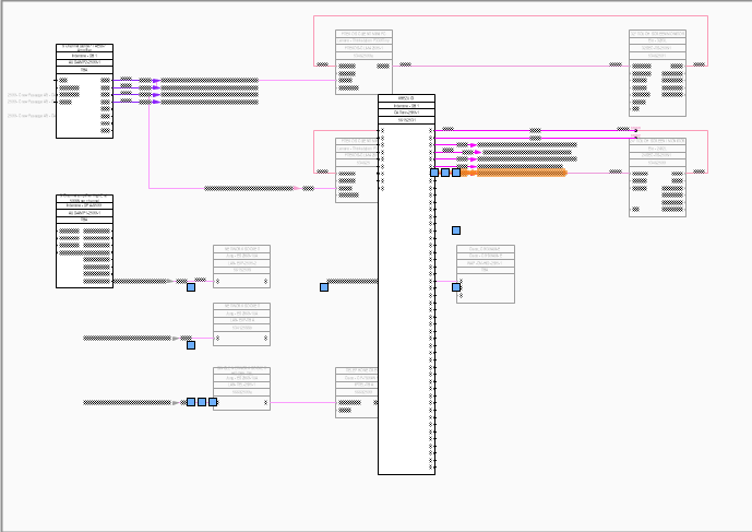
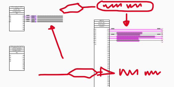
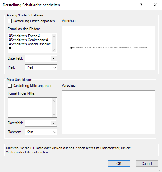
good morning, and in case you or @Conrad Preen are wondering why one would want to reshape these flags: there is no way i can see to arrange those circuits with lines being equidistant and the arrows still lining up vertically? or am I missing something?
-
This does get the job done indeed. Thank you. In the german version the general setting for circuits is not under General (doesn't exist), but under the "Units" tab... which makes no sense at all. 🙂 Well, different countries/industries/companies... different standards, I guess. 🙂 (But it does actually have it's benefits too, depending on schematic size and amount of cables coming in/ going out) Guess, I will have to make this post a feature request? 😉 First idea: Since the cables represented by cable jumps are somehow drawn in the background anyway (blue squares in image below, when I select a cable jump with the Reshape tool), maybe it could be set up in a way, that one can decide, how much of the cable on either side is shown? Then I could draw the invisible cable connection however crazy I want. Thanks anyway. 👍
-
Hi @Nikolay Zhelyazkov fyi only: Turns out, this is kind of a bigger issue than expected for our client. (Sticking to the drawing standard with arrows coming in from the top left and leaving the schematic page on the bottom right). I am playing around now with other options (e.g. adding sort of a virtual termination panel to allow me to re-route the cable coming in/ going out and label it with data tags... which at the current state will be a maintenance nightmare... any other ideas?), but without much success. 😕 But linked issue: Where can I set the layout for *all* circuits? (e.g. arrows for all of them instead of boxes (a) or what kind of info is on the label (b).) It's neither in the ConnectCAD settings nor the classes. And I can use something like the pick up tool to apply it to all my circuits? Thanks. Best, George a - Different cable styles in the same schematic. 😞 b - Local/individual circuit settings
-
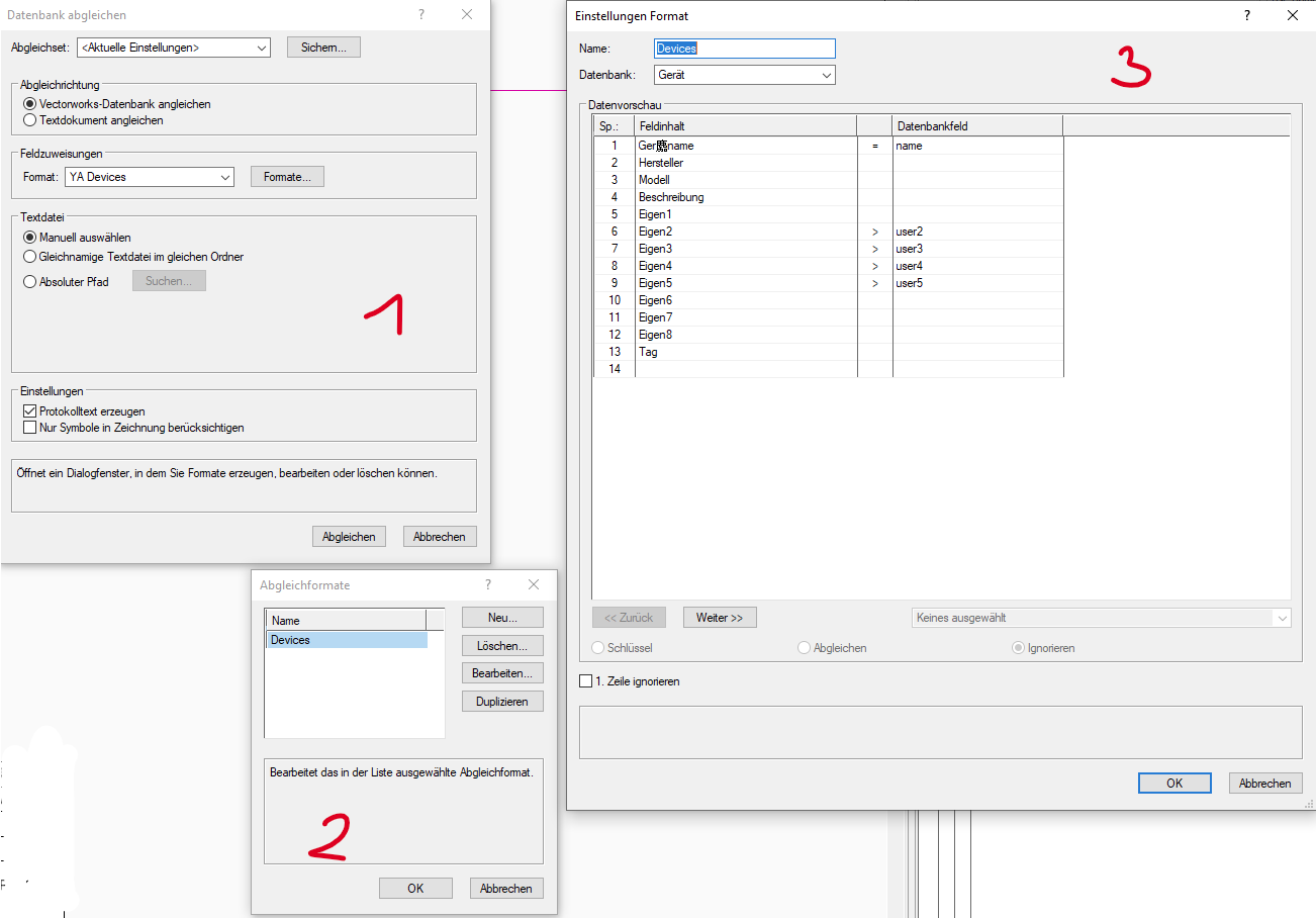
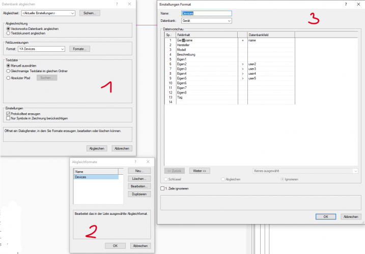
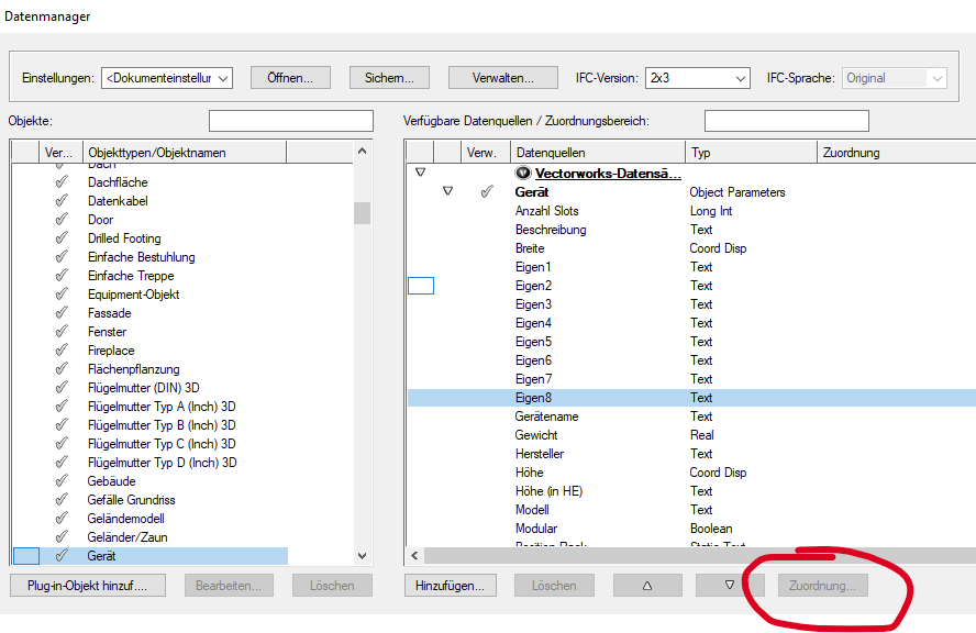
Update: Finally got the feature to work. So, if you have the EU Version of vectorworks you can use said tool to update VW records from an external spreadsheet and vice versa. 👍 You'll just have to use the "Devices/Geräte" not the dev_rec record to compare your file to. (Silly mistake I made. See image below) ...seems like it actually is. 😕
-
Hello, sorry, to pull out an old thread again, but this is another issue I am currently trying to resolve for our use of ConnectCAD. tl;dr: Has anybody successfully used the "Compare record to external document"-feature (german: Datenbank mit externem Dokument abgleichen) with devices and dev_rec? long version: I am also struggeling with the best way to update PIO data with an external spreadsheet. Updating make and model might even be a more difficult task, as you might end up with different inputs and outputs, but I would like to update things like customer device ID, parent system, room ID (linking the schematic with my general arrangement plans is on the list to do for the months to come. 😉 )... Doing this in excel is very easy/fast as you can also use stuff like vlookup() etc. what @modbom describes is exactly what my colleague would have done (we also are currently still using StarDraw) and I use attIn/attOut in AutoCAD for our other types of documents on a regular basis. Got another hint for a feature to compare data records (e.g. dev_rec), but I can't get it to work with dev_rec, as dev_rec is not connected to the device but to the device_label inside, right? (It works perfectly fine, when I add only the device_label symbol to the schematic) Is this function not supported? (as it is missing in the Extras-menu of the ConnectCAD environment) Can't be an EU-version only feature. Thanks for any hints! Best, George
-
note to self or anybody interested: this is only a update-issue. since the mapping is in the device_label symbol, switching all symbols to e.g. (e.g. TP_label) and then back to the actual device_label will update the entry. ✌️
-
Yep, that always works, I guess. 😉 (But it's still good to know/understand) But you're absolutely right! Why not use a different field, that is not visible. As I don't want anybody to change the "Make - Model" field anyway. Thanks as always for your help!
-
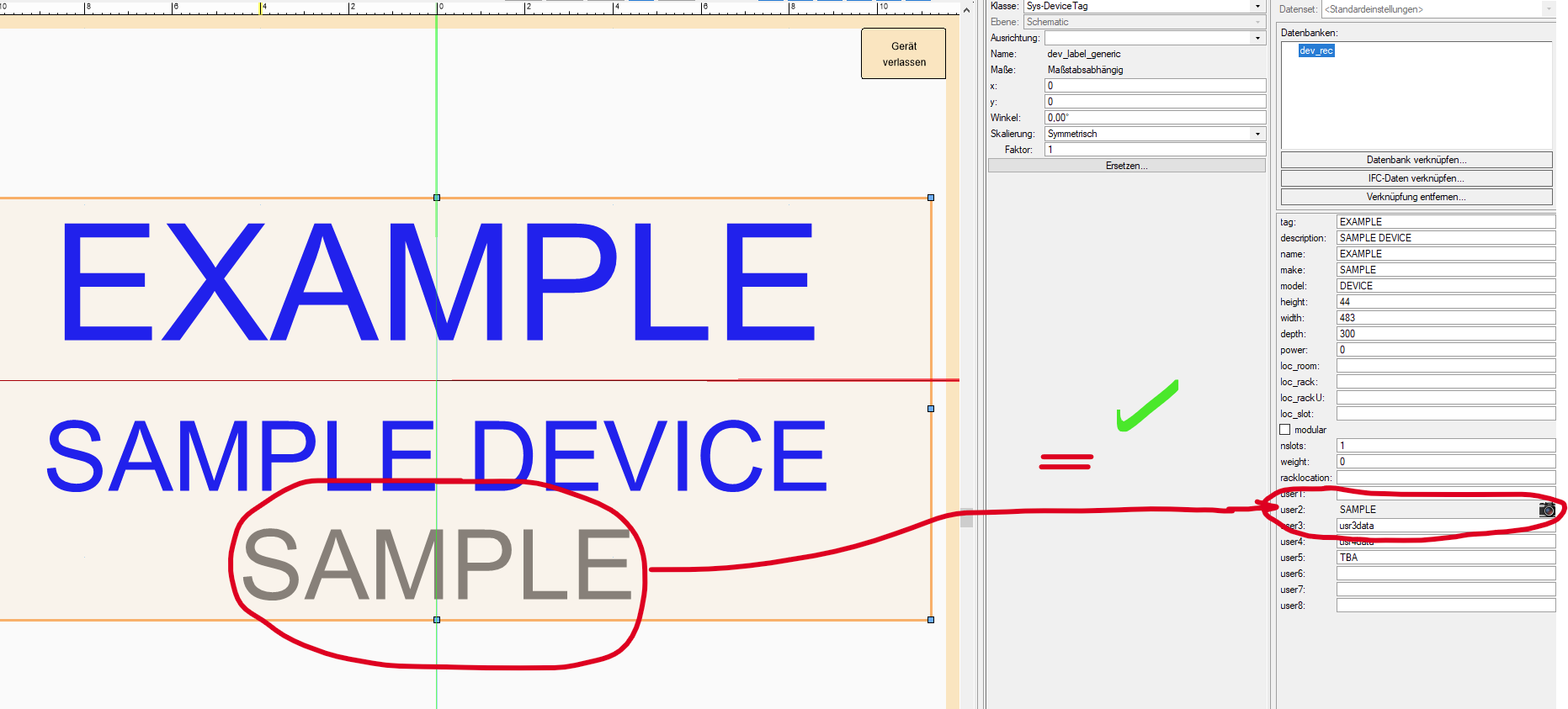
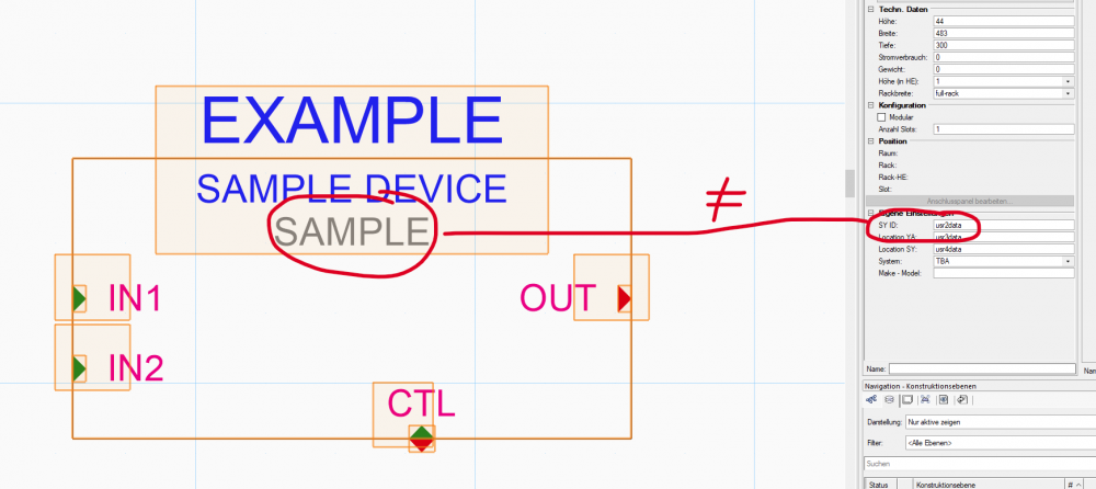
to me it is somehow irritating, that my user2 field in the OIP of the device is filled and editable ("usr2data"), although the user2 field in the dev_rec of the device_label is showing the correct make and model. which is also correctly shown in the LinkedText Field in the schematic... if that makes sense.

-
hi @Nikolay Zhelyazkov, of course! thanks. kool. i think it's almost there. 🙂 (of course there's a "but".) 1.) but if that is the case, why isn't the PIO info in the OIP changed accordingly? you can see what I am talking about in my screencast starting 1:04. I am changing the dev_rec of the device_label inside the device. but once I am leaving the device edit the data is gone. 🤷♂️ 2.) the other issue is with the field update. I have set the mapping in the data manger to "by mapping" (with the little arrow sign), but I still have to manually enter the device, select the device_label and click on the little 4square symbol for my mapping to show up. why isn't this set by default (happens for both "by mapping" options) ...1min after writing this... never mind. I just have to change the base symbol of my PIO in the resource manager. of course. 🙈 (leaving it in for anybody how might run into the same problem and is crazy enough to read all this.)
-
thanks @Nikolay Zhelyazkov, I tried that too, but what I described with a custom DB also is what's happening with the dev_rec. 😕 that's what I meant by "I just still don't understand, where the info shown for the PIO Device is stored and how I can access it". 🙂 here's a little screencast of what I was doing. (obviously, I don't know what I am doing.) where is the device_label symbol inside the PIO "device" pulling it's info from? VW_dev_rec_mapping_.mp4
-
Hello all, started a new topic, but found this while having a general read through the forum topics (I can't remember having such a hard time to learn about a software. well, maybe, blender. but only because there are too many tutorials. due to the price tag, I guess. 😅) so, if you find @hihosilvey's approach "interesting", what would be your recommended workflow @Conrad Preen? (I can still do it differently, if I want. 😉 ) because I am really struggeling with the file setup. (having all on one layer is nice, but then I have to find a workaround for the layout frame reference, if the schematic is not in the center, having seperate layers might be better for the layout arranngement, but then the issue of automatic sheet numbering remains, having different files is nice for sheet numbering, but... I don't want to bore anybody. you get my point, I hope. 🙂 ) tl;dr Is there any chance for a one or two sample setups? As a video or a sample file. (the "VW University" is a great idea, but lacks a bit of ConnectCAD insights. IMHO) thanks so much
-
Hi @Nikolay Zhelyazkov had another look at the data manager, but from what I can see, I can not change the mappings for the PIO "Device"?! (All I can do is add another record (Datenbank in the german version) e.g. CustomDevices and adjust the mapping there. But that data associated with the PIO Device will not show up in the device_label symbol inside the PIO. Maybe I just still don't understand, where the info shown for the PIO Device is stored and how I can access it. Sorry.) Edit: the mapping is greyed out. 🤷♂️
-
[solved] Devices with lost connections after Copy-Paste/ Cut-Paste
elc replied to elc's topic in ConnectCAD
copy that. 😉 thanks -
[solved] Devices with lost connections after Copy-Paste/ Cut-Paste
elc replied to elc's topic in ConnectCAD
My bad! I was talking about and showing a copy-paste action (in which case keeping external connections makes absolutely no sense) when I should have said cut-and-paste. sorry. 🙈 Still, that operation doesn't work either. But maybe, I misunderstand: I only want to move the destination objects (speakers) from Layer B to layer C. The source object on Layer A should stay where it is. And you're saying, that is not possible? I have to somehow move the source as well? -
[solved] Devices with lost connections after Copy-Paste/ Cut-Paste
elc replied to elc's topic in ConnectCAD
I see. But that means, I can't copy devices with connections on other design layers? 😕 -
[solved] Devices with lost connections after Copy-Paste/ Cut-Paste
elc replied to elc's topic in ConnectCAD
Untitled.mp4 i really only use copy-paste. -
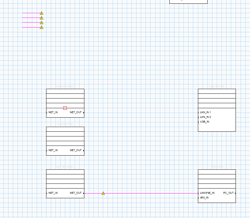
hello all, when moving devices from one design layer to the other they lose their connections? (yellow warning sign) arrrow connections are even moved together in the center of the drawing. feature or bug? ...or is it simply my fault. thanks for any info. best, george
-
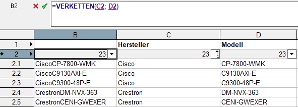
each device has the following fields: name tag make model ... user1 ... user8 my idea was to combine "make" and "model" inside my worksheet (column B above). but use this column as the entry of user8. ...if that makes more sense. 😄 but within worksheets I can only pull attribute info *from* objects and not write attribute data *to* objects? Edit: For now I used copy-paste, but having the fields populating automatically would be way more handy... and safer.
-
"Currently" sounds very promising, thanks. 😉
-
reg. 1.) Fantastic. That's almost exactly what I was looking for. Unfortunatelly with ConnectCAD linked text in my PIO instead of in the symbol device_label I run into the same problem as in my first question on custom device labels: when I want to make change later in the project, I will have to use the pickup tool on every single device type to update. which might be around 200 to 300. 😕 reg. 3.) Fantastic 2. works like a charm for my additional column. And is it possible to write to an attribute (overwrite 'Device'.'make' with TextVerketten(' - ';'Device'.'make'; 'Device'.'model'))? but I guess I end up with some sort of circular reference.
-
Thanks @Nikolay Zhelyazkov, 1.) yes, I have used the device builder, but some devices where created with "copy, paste, adjust" 😉 because it was faster. Hence my question, if I can add those to my DeviceBuilder DB withouth hacking away in a text file again? 2.) That's a bummer, but I suspected as much. But at least they would be in the drawing and I can use the ConnectCADs special Device picker tool. I'll just give that a shot. Thanks
-
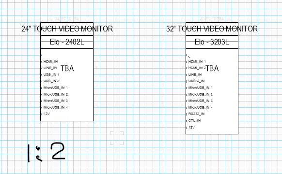
As I would like to have Make and Model of a device in one line, ... 1.) I was looking for a way to join Linked Text arguments in one text field. But I guess I can't? 2.) Then I just used Data Tags, where I can do just that. (e.g. #Device#.#make# - #Device#.#model#) But ran into problems with scale (some schematics are larger then others, but I couldn't find a way to have data tags scale with the layout. (e.g. 1:2 instead of 1:1) (Goal: have larger schematics on one Design Layer but different Layout layers... or is there a more elegant solution) 3.) And my last attempt was with tables, where I thought I could fill in the attribute fields with table functions, as I would in Excel. Am struggeling with the functions as "TextVerketten" won't work (but thats for the EU forum, I guess. 😉 ), but the main issue is that I can't fill attribute fields with functions, right? (as a column is either a "Database" or a "function" column?) As always, thank you for any hints in the right direction. Best, George
-
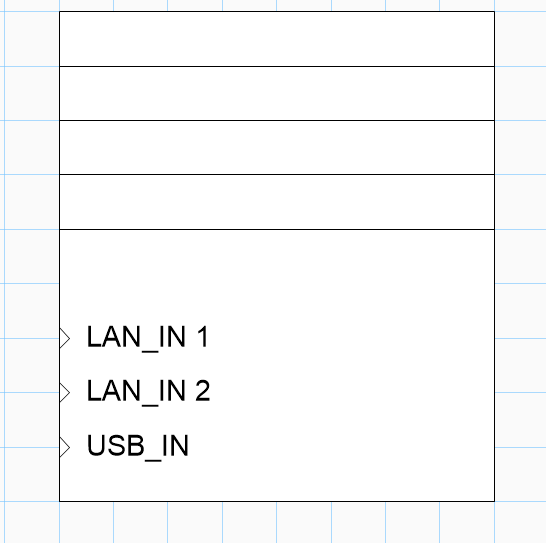
Hello @Conrad Preen, sounds good. Because I was about to edit the file and realized that it is not formatted for "comfortable editing" (e.g. edit in Excel like the tabbed CustomParams.txt 😉 ) But the question remains: 1.) How can I add symbols in the ressource manager to the DeviceBuilder list? As I understand, a device has to be in the device builder list in order to be recognized for "Creating devices from a worksheet", right? (at least that is what happened, when I tried it.) 2.) But then again, if the devices are created by the device builder, they can't have a custom look (e.g. a 4 row header before the first connectors as seen below) So, how can I add custom symbols from the ressource manager with the worksheet function? Thanks for your help. Best, George
-
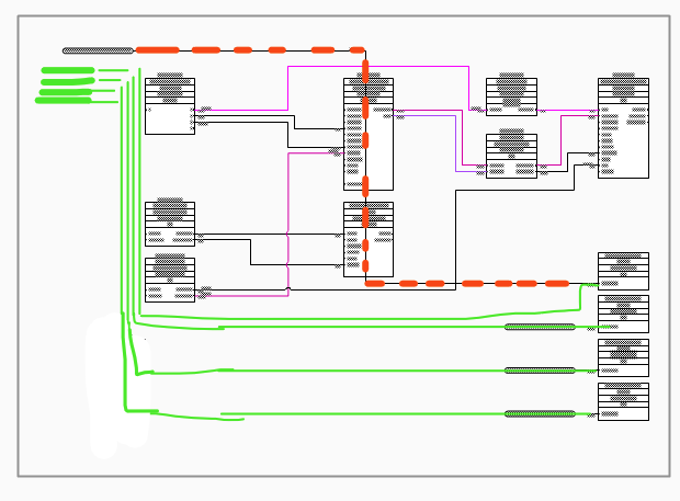
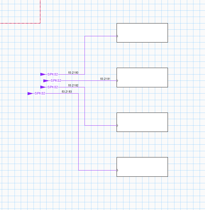
Hi @Nikolay Zhelyazkov great, thanks for the hint. Is there also a way to change the route of the cable path? as far as I can see, I can't adjust the path in your sample screenshot with the reshape tool, right? same for the destination. changing the offset allows only for to changes of direction and the vertical line appears to be always in the middle between destination and flag. (red) what I wanted to achieve was grouping all incoming cables of a schematic page at the top left (green) and all outgoing cables at the bottom right. guess this can't be done?