elc
-
Posts
138 -
Joined
-
Last visited
Content Type
Profiles
Forums
Events
Articles
Marionette
Store
Everything posted by elc
-
hi @Conrad Preen, yes, exactly. any of the standard record fields or at least the cumstom user fields (1-8). but I was thinking ot the devices (source/destination) only. don't have VW with me right now but I couldn't think of any socket records I would use other then the name itself. thanks for looking into it, george
-
Best practice for setting up a project with multiple rooms/locations
elc replied to elc's topic in ConnectCAD
hi @Mark Aceto, that's a good questions, that can't be put into two sentences. what I've learned so far though, is that it greatly depends on what your final outcome has to look like. In my case I need A3 sheets for each room. And I don't seperate systems (audio, video, control, IT,... and so on). Everything is in the same drawing. Also I am not using Spotlight. I am really only here for ConnectCAD. At least for now. But the file is huge (40MB) already and tools are starting to get slow. So I am not sure, if I really want to explore all the 2D and 3D options VW gives us. 😉 But in a nutshell: started out with one layer per room and am (in a second project) trying the one design layer per floor approach due to technical and workflow issues. A bit more details if you are interested: Since I haven't heard back on the forum, I just started with one design layer per room. While layers/rooms with a lot of equipment have to be spread out so they can be printed on seperate layout sheets. (might require arrow connections for in-room equipment). Main reason for this was that I could assign the room name to the layer and reference the layer in my said arrow connections (e.g. "--> Layer/RoomName - Device Name - Port Name"). But the workflow of moving arrow connections between layers is not as fluent as one might hope. And I had issues with inter-layer cabling (lost connections with no solution yet). Which is a pain when you try to move large amounts of devices with a box select. But it seems to happen mostly(?) to EXT devices. I don't know. I just try to select the devices without the arrow connections. But I am getting off topic. 😉 Because of the above unsure situation and the fact that a few tools only work on the same layer I wanted to try to keep the amount of layers for the schematics to a minimum and only have one layer per floor. Let's see how that goes. 🙂 Again a pretty long post, sorry. But it is still just a fraction of the issues questions I would still have. 😄 Still in the trying-to-wrap-my-head-around-VW phase though. Hope this helps anyway. Would be intersting what you decided on and what output you have to generate regarding paper size and system separation? (We were also thinking about just going with A0 for larger rooms instead of multiple sheets and arrow connections) Best, George -
Worksheets, adding rows and columns
elc replied to ScottLebsack's question in Wishlist - Feature and Content Requests
thanks @drelARCH for the hint. it is acutally the way I added rows and columns so far, but it is a bit tedious when you have to add let's say 1000 rows (although chessboards and rice come to mind). and the "drag to add" doesn't just let you drag infinitely, but only to the edge of the screen from what I can see. (it also doesn't give you a row count of how many you added.) ...just to give some feedback on why I would greatly appreciate a different option to add columns. 🙂 I thought, that's where we are right now? Or should I open a new topic? -
since it is causing me trouble again: may I add another "tiny" future/feature request? 😬 In another post @Nikolay Zhelyazkov mentioned that the circuit description (for arrow circuits) is limited to a select number of data elements for source and end device. a bit of context: in my current case, I am trying to reference the room of a device which is stored in a custom user field instead of having to place every device in a room in the rack elevation view) unless I missed another option (can't put it in device name or tag): any chance that these will be extended? not sure, what part of the programming requires a limit, but maybe the user data fields could be added? (where anything could be stored via the data manager) thanks a lot, george
-
Worksheets, adding rows and columns
elc replied to ScottLebsack's question in Wishlist - Feature and Content Requests
@Pat Stanford that drag to add rows/columns feature is pretty handy. possible feature request: is there any way rows could be added when pasting content? e.g. I would like to paste content with 50 rows in a worksheet with 30 and VW just adds the additional 20 automatically? or a dialog asking for the amount of new rows? (or both 😉 ) thanks, george -
Good morning, let me start out with: I am a happy renumbering user. While I understand things shouldn't get overcomplicated, there is one use-case that maybe you could look at? --> renumbering devices with more then 1 digit with the first digit staying the same. e.g. I'd like to renumber: Device-32, Device-33, ... to Device-38, Device-39,... or Device-120, Device-121,... to Device-150, Device-151,... Currently, I can't. As CCAD creates: Device-3-38, Device-3-39,... and I have to change all devices to Device- first and then start renumbering starting with 38. (given that they have the same name/ are of the same device type. Wouldn't work in @JonnyAVC's case) Possibly give the option for a current prefix (what to look for, with none as an option) and a prefix for the renumbering (as done currently)? best, g
-
As I am working on the rack elevations new questions start popping up. Like general questions regarding the way rack elevations can be drawn in ConnectCAD. here's some feedback/ feature request: As many of our clients are used to getting detailed rack elevations showing line drawings of front and back of almost all rack equipemnt, it would be very useful if all rack equipment could really be represented by a symbol as well. Currently this only works for regular equipment (RackU 5,6) and for single cards (Slots 1 and 3 in RU9), but not for rack frames (and possibly for the actual rack). Hope, there is still some space on the team's issue tracker. best, george

-
hello @Nikolay Zhelyazkov, since scripts are still unexplored territory: any plans that this will be implemented as a standard feature? device and equipment kind of represent the same piece of hardware and are linked already (via name/ID, make and model)? edit: and I think your nice method of using worksheets does not work with user-n fields only with custom records, right? I couldn't get it to work. 😕
-
That's the thing, I would like to avoid rendered (pixel) views in the documentation, as it is very limited in use. Scalable line views (vector) as in all other CCad documentation elements would be the ideal. For now I'll just use a. - the classes-for-views-with-a-flipped-rear workaround. 🙂 as always, thanks a lot for your help and taking the time. learned a lot again. best, g
-
a. yes, that's what I figured, but then the Rear view has to be mirrored in the symbol, when using your method of mirroring the hole rack frame, right? 😕 b. yes, I had tried that too. but then that change only applies to that single instance of equipment. not the other ones used in the rack. and this time around I can't use the device picker tool to apply the same to my other items. or did I do something wrong? c. yes, I had tried that as well. :) but the problem for me here is that I can only have a rendered view of the 3D object and not a flat line view. or not? d. have you had a chance to look at the section view path as seen in my file? this would be the best option to me, but I just can't get the 2D views to work on my layouts. (since this is one of the main benefits of VW: combining 2D flat views for printing with 3D rendered views?) best, g
-
oh, an one more thing: 2. is it possible, that rack frames (frames inside racks) won't show the individual items in 3D view?
-
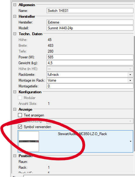
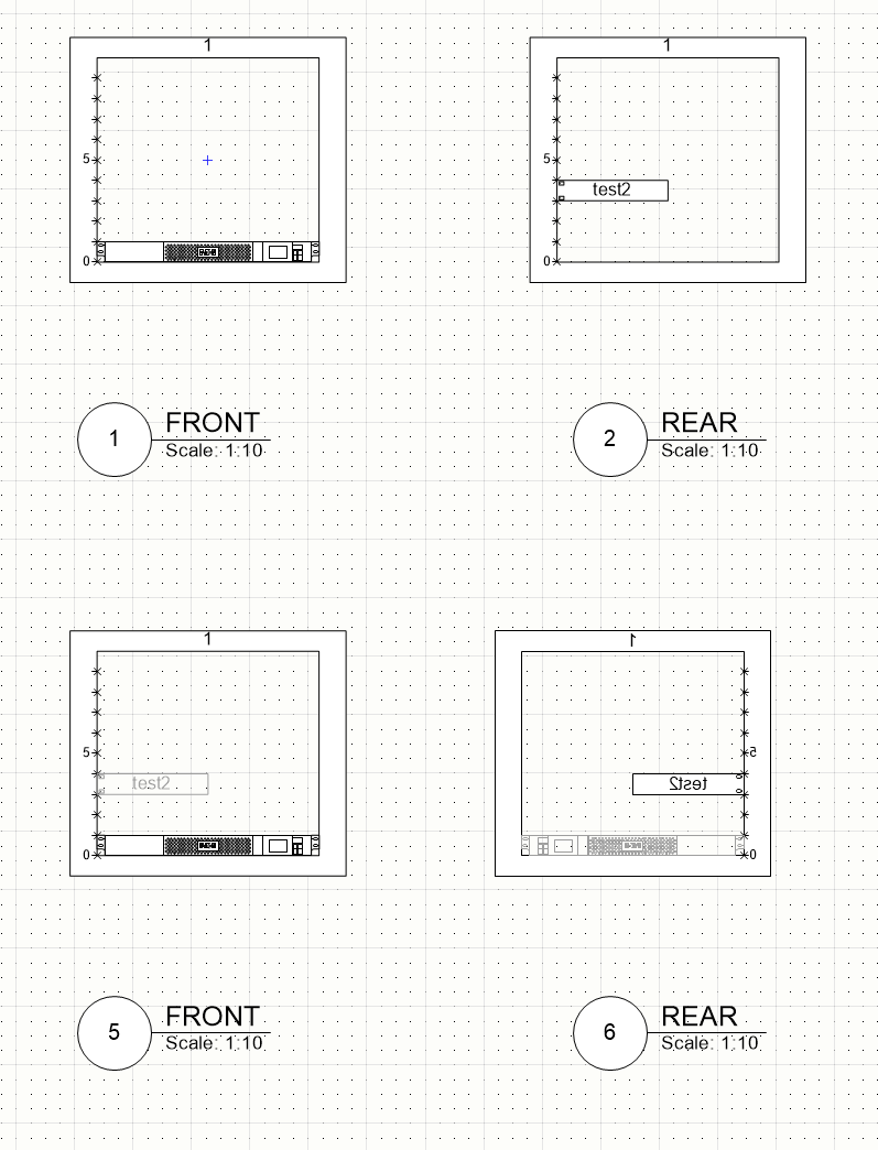
sorry @Nikolay Zhelyazkov but I can't find a way to add different views to the Equipment Item. I assumed I have to create a symbol and connect the equipment item to that symbol in the OIP (please don't mind that the symbol does not correspond to the name. 😉 ) edit: and it only shows the top view of an object (not the front) in that symbol I have created front and rear views of the object, but *how* can I display them? https://app-help.vectorworks.net/2022/eng/VW2022_Guide/Symbols/Concept_ 2D_components_for_symbol_definitions_and_plug-in.htm#h btw I tried working with section views. looked promising. but with no luck. the 2D views just won't show up. 😕 (see attached modified file) Half-rack rear mounted and symbol insertion point Test_g.vwx
-
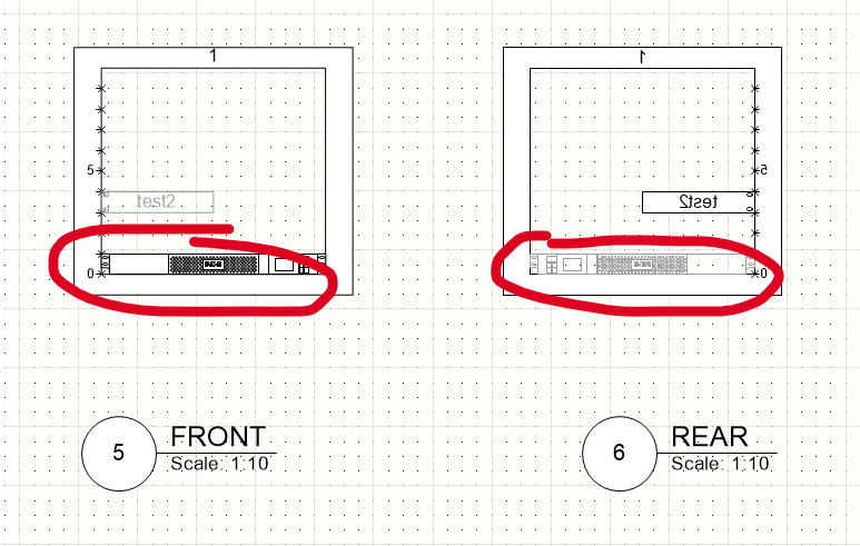
hi @Nikolay Zhelyazkov, we might be talking about two different things? I don't mind the rack ruler position, it's about the view of the devices. both front and rear view show the front of the bottom device (while the 2D text of the half rack device is mirrored). or what is it you meant? 🙂
-
btw: think I found a workaround using the detailing option of 2D-plan views. but that would be just that, a workaround as it is quite fiddly.
-
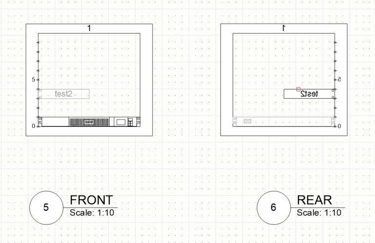
Hi @Nikolay Zhelyazkov, am facing a similar issue as @Rune Røsten: I would like to show a front view and a rear view of the racks pretty much the same as the OP. (the rear view shows the front of the rear equipment and the back of the front equipment) pretty much like this google visio find, but as a line drawing only (no colors, shades etc): this is what I get when using your rotate method. looks almost right, but I still only see the 2D-plan view side (front) of the equipment mounted in the front: how would you show the rear view of a rack in plan view? is there a way to make use of Vectorworks' 2D views (front, rear, top, bottom, left, right) for the plan views?
-
@Nikolay Zhelyazkov wanted to attach records to the racks via the data manager, but I can't seem to find the rack elevantions there as PIOs (going by the name in the OIP). did I miss something or are these not PIOs? (couldn't find the rack frames either) thanks, g Edit: sorry Nikolay, just finished your Data Manager video... where you explain exactly that (@5:10) ("Add Plug-In Object..." in the Data Manager) Not used to watch ConnectCAD tutorials, I guess. 😉 Thanks for the video!
-
To be fair, there is a fair amount I disagree with Conrad's approach on some things, but his logic here is sound in my experience (In terms of why it makes sense that every instance of a device is not a symbol that would be tied to every other instance) as all of these are perfectly valid things that I have done repeatedly. Now whether this is an argument about making each device an instance of a unique symbol vs a plugin, eh that I can't weigh in on. yes, @Thomas_ It looks like most people use it the way you do and the system was designed, I can see that now. Guess I misinterpreted or misread a statement made somewhere else, sorry about that. I understood devices have to be PIOs as the circuit connections wouldn't work otherwise, hence my comment of a suspected "systematic issue". But I guess that is wrong or at least not the main reason. and sorry for going waaaay off topic. (: sorry, @Conrad Preen I didn't want to go into detail on those points as I felt I just might know too little about them yet. Especially when the function in question would not be revisited as stated. but I will try to elaborate a bit (see below). tl;dr: the main reason why I wished for symbols instead of POIs is that in my current workflow the amount of work I have to put into changing types of devices at a later stage and possibly missing some changes trumps the other drawbacks in your list. For now at least. 😉 best, george > a) because editing a symbol changes EVERY instance of that symbol and you may not remember everywhere it was used until your installer/technician comes up against the problem that is actually what I am after in a file and the eyedropper is a fine tool, but it doesn't feel as inuitive (yet) to me as it maybe should. for example: 1. All layers have to be made visible, all devices selected and then I have to make sure the "master" device is clearly visible and selectable between the other 200 now appearing devices to get the features I want with the eyedropper. That felt like many extra steps for a small change. 2. Renaming sockets doesn't work that way when a circuit is connected. I can bulk rename them through the worksheets of course. (although only with another workaround) but that's again many extra steps. (though I have to say again how fantastic the editing capabilities through worksheets are already) rough idea: as with other symbols used (e.g. the ones for the connector text) VW could ask what should be done with devices in a drawing when pulling a similar device from the library into the drawing or when the master device in the library was updated when opening a file? (maybe similar to how fusion handles external components? probably not feasible) > b) it is very useful to re-order the connectors of the same type of device in the schematic to reduce the number of circuits crossing over I can see how that is very practical although I didn't really consider this a problem yet. > c) it makes for much clearer drawings if you do not clutter them up with unused connectors I can only assume that this is indeed very good for many drawings. e.g. with audio or lighting mixing consoles and such? but we don't use those, so I don't know. in fact I was specifically asked at times to draw available connectors so that when revisiting a site for an update or while remotely troubleshooting, support can see what is still available on a device. it does add redundent info to the drawing but in our case it wasn't too distracting yet (and I do leave connectors out that are extremly unlikely to be used) > d) you may well want to have the same device on multiple layers e.g. and audio / video switcher will appear on the audio schematic and the video schematic but with different sockets showing not using layers separating systems (yet) > e) you need multiple instances of the same device (but different sockets on that device) in different areas of a schematic to have a clear signal flow - example: patch panels. similar use case as c) and d) and I definitely see the benefit in patch panel devices being different to regular devices (although for now I decided to treat patch panels as modular devices to be able to spread them out on the schematic instead of the standard patch panel device function as they felt harder to read.) also the use of arrow connections very rough idea (for c,d and possibly e): have different "visibility states" for each socket of every device instance. (which sounds impossible to do in a userfriendly fashion of course)
-
that is indeed a problem. but thanks for taking the time to answer anyway. much appreciated. yes, I hear your arguments! but from my current experience I can not agree, sorry. but that may very well be due to a lack of experience on my part! and I guess it also depends at what point in a project you are. may I add that your list does have quite a few implications on how the software "should" be used and how schematics "should" be drawn. which makes me wonder again, why VW is not offering more specific tutorials or workshops on ConnectCAD (and not just "Entertsinment") and how to use ConnectCAD in particular (aka BestPractice)? I am sure you have and I can understand that having the same topics come up with the new guys like me is frustrating. but I always felt having this kind of exchange of views also adds to refining the software. as obviously not everybody has the same workflows. not sure at what point you felt a lack of respect for your work again but there sure is none. on the contrary, as I said before. just a bit sad, that this topic shifted from it's initial topic, which is the device builder and further down feedback on how to possibly improve its options.
-
oh, cool! didn't know the socket tool could directly edit device objects (although I don't quite understand how that makes it fastern then opening the device edit mode as I most likely have to change my device rectangular to add sockets as well?) (btw another case of: Why not make a real ConnectCAD tutorial that explains what it can do in half an hour? I still don't understand why there is so little easy access documentation on ConnectCAD. And I am not talking about the long -randomly detailed- VW help.) which is why I was asking about what US/international standard for connector types and abbreviations you were thinking of. 😉 Difficult? Not really though when you find you need a connector not in the list for new device you don't normally work with, that could be easier. Tedious? Very. maybe for other reasons, but thanks, that's the word I should have used. Tedious. Didn't want to cause any concerns. 🙂 Don't get me wrong, I kind of like the device builder, but more often then not I find myself in the position, where it is just too time consuming to make edits there. As a tiny example (but maye I missed another function as well 😉 ) : Let's take an amplifier with speaker outputs for 2 speakers and spdif loop. 1. if I want the outputs to be called SPK L and SPK R I have to create a new output line (can't duplicate it, why?), as the default 2 output function only allows SPK 1 and SPK 2 and set all those good settings again (signal type, socket, cable)... Excel 10sec. 2. asuming it is using a coax cable I've set the spdif output accordingly and name it Digital Out. later on I am told that it is using a regular shielded stranded wire and am changing the cable type, that possibly changes the connector type and name automatically again, so I have to click around to get those updated. Again in a worksheet 5sec. Maybe not the best examples. Obviously the above is do-able, but if you have that issue wih every other device and 10 ports each and might want to make changes at a later stage... I hope it helped illustrate my issues I am having with the device builder. Some improvements I could think of... for starters it would be great, if the device.txt would be a lot more ´"Excel friendly": e.g. headers and make and model or any other column (e.g. a random device ID) on every socket line for easy sorting. Maybe in the future when VW is a bit further with it's usability with worksheets/tables the worksheet edits could be done inside VW?!) maybe doing it in VW would eliminate another issue: not having to restart VW to make edits to the device.txt one of the biggest issue I am having (of which I know it currently can not be changed as it is systematic) is that the devices are not symbols but unique plug-in objects. I still have not read one convicing argument other then "It's how it has to be done, because that's how VW works"... which obviously is something that can't be argued against, I know. But let me dream, thank you. 🙂 Again, the device builder is a nice tool and I use it for small edits, because it's all in a neat selectable list. Just hoping for a few updates so I don't have to use all of the current workarounds (to deal with the points in my list above).
-
good point. once it is added from the device manager, the corresponding signals and sockets are added to the lists? but to make it easier for myself, I currently don't use any pre-defined objects anyway. as I might not like the naming of outputs you've pre-configured or the order. that's why even if (currently on the rare occasion) the device is in your list, I just copy it and add it to my user data. I then just give them "none" as device group, so I don't have to deal with another drop down menu in the device manager. (as it is always set to the wrong group anyway, when I create a new device... murphy's law and all.) the search function for make and model is all i need. currently. but that is only my workflow after 2months of VW. probably will look a lot different in 6 years. on that note: don't listen to me. 😄
-
oh, wow. this is getting interesting. Not sure if it is possible to have a library that works for everybody. Especially if I want to add a device "now" and not wait for it to be added by VW. And the goal of "without it becoming a major drain on [your] resources"... I don't know how that is going to work out. There are quite a few open issues as is. IMHO But making device creation a bit more comfortable could be a huge help (and factoring in external edits)? And this sounds interesting and frightening at the same time, because it seems to be a big constraint on the custom schematic design? (Wouldn't work for us currently, as we like to give our cable and signal types custom names.) What would be the ISO document for said "standardization"? 👍 As mentioned before the language route VW took is currently a huge pain (at least for my German version). Especially because the localization adjusted variable names (the tags for variables so to speak), which caused a lot of frustration in my past first VW weeks. 🙂 Any improvement on that end would be a huge relief. In our case, having the user content on top is perfectly fine. But if that switch could easily be implemented, why not? Not sure how practical one switch for all content would be, though. Maybe one switch per content type? (numbering, cable types, signal types,...). my 20c. for what it's worth. 🤷♂️
-
Ability to make any Class or Layer be Non-Plot
elc replied to rDesign's question in Wishlist - Feature and Content Requests
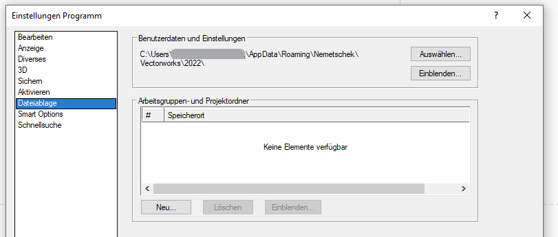
nice one @rDesign 😄 got my upvote. still no new development, I assume? the best I could find regarding this is to just make the nonprint classes translucent and set the visibility of grey objects to 0 (screenshot (5) in this german help and english) obviously that only helps, when you don't need the translucent classes or layers for anything else. maybe this approach is useful for someone looking for a workaround to this basic request without any Vectorscript or other shenanigans, like me. -
thanks @Nikolay Zhelyazkov and this shouldn't be a problem?
-
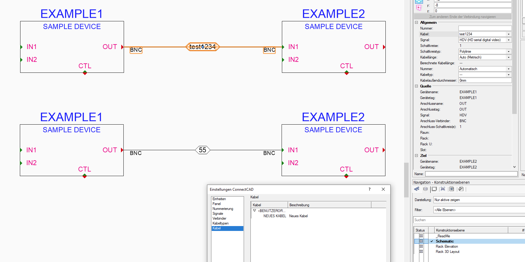
Sorry, but I can't really send a useful file as in the above example the CableOptions.txt was blank. This is what I did: CableOptions.txt must be empty (the one in the user folder) manually type in a Cable type on one of the circuits add a user defined cabletype ("Kabel" or cable option in english, I guess) in the CC settings now you should have that user defined type and the manually added one in the drop down list 🤷♂️ What I do remember though, is that I had four columns in my txt file before (<Benutzerdefiniert>, =, =, = ). but in my latest one there are only two columns (<Benutzerdefiniert>, = ) . Maybe that was it? On a side note: Just saw the other day that VW gives me the option to define a custom location for my user data? Guess I'll chose one in my documents folder which is synced with sharepoint to have a version history of my CC settings files... or is that a bad idea for whatever reason @Conrad Preen?
-
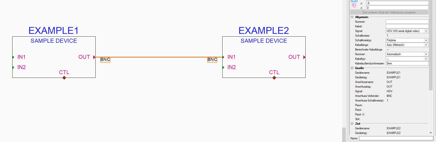
hi guys, not sure how, but my CableOptions.txt file is empty. All my entries are gone. Which I only realised because the dropdown was missing next to "Kabel" (obviously "Cable [option, I guess]"). Just last week I noticed cable options in my dropdown list not being listed in the CC Settings dialog. Guess it has to do of how the dropdown list is created? As I can manually enter values (see below) and when adding a value via the settings dialogue the manually entered values (e.g. test1234) are also listed in the dropdown but obviously not in the settings. gues the initial error had to do with me editing the CableOptions.txt outside of VW. Although it was working fine for the last days. And I didn't do any edits.Is there any posibilty to make these config files more robust? But please don't just answer "Don't edit outside of VW". 😉 (Editing these things inside VW takes ages.) Thanks, George