elc
-
Posts
138 -
Joined
-
Last visited
Content Type
Profiles
Forums
Events
Articles
Marionette
Store
Everything posted by elc
-
Thanks for the info @Pat Stanford, that's a shame, as it is inconsistent? but... ...thanks a lot for the suggestion @michaelk! another "why didn't I think of that?! but luckily there is always some very smart person on the forum that knows exactly what to do"-moment. 😅 with the above example ... & (Left(Layer;4)='1*') & ... worked like a charm.
-
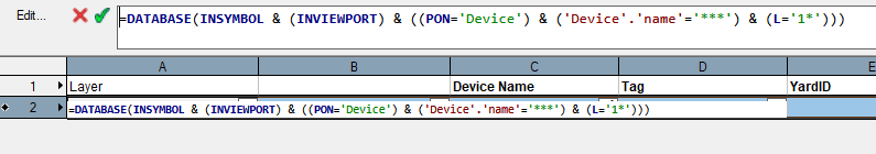
Hi @michaelk, thanks for looking into this. I am using wildcards quite a lot and they work everywhere (or at least everywhere I needed them so far 😅) except for the Layers. Lets say you have layers: 1001, 1002, 1003, 2001, 2002, 3004... but only want to select all devices ('Device'.'name'='*') on layers starting with 1 (L='1*') that does not work for me. The resulting list is empty.
-
Hello, I am trying to adjust the report criteria so that only objects on specific layers show up in the worksheet. Is it not possible to use wildcards? Thanks for any hints.
-
Changing device names with "Find and replace" does not update equipment link
elc replied to elc's topic in ConnectCAD
minor update: still seems to be an issue in SP4 current workaround: just creatin a worksheet and copy pasting all the required equipment names to itself is enough to re-write the link between equipment and schematic device. Best, george -
ah! was wondering what I can edit and what I can't. now I know. 🙂 thanks a lot @Pat Stanford no need for a script (haven't played enough with these yet. will do in the future though.) I'll be taking the manual route. but thanks!
-
Hello, am trying to rename viewports in an worksheet, but the object name can apparently not be edited? (tried: =NAME, =N and =OBJECTDATA('general name') Is there any other way?
-
Hello all, picking up this old thread because I'm curious: Are you @El Dinyo using this method from the beginning of creating a cloud? Or is this realy a cloud from an old revision, that you edit at a later stage? Because I couldn't find a way to convert any shape into a revision cloud as you can do it in "other software" e.g. by going REVCLOUD>O(bject) Or is there a way and I haven't found it yet. Thanks
-
Hi @Nikolay Zhelyazkov thanks for looking into this. Unfortunatelly it doesn't help much, as I don't work with signal types (Signal is more used to define the cable type and therefor the class formatting). Best, George
-
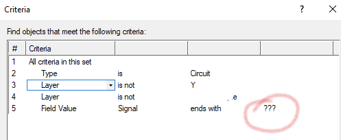
hello all, Couldn't find anything on the forum or the Help: I try to list all circuits marked "???" as the signal type in a worksheet. But ? is used as a wild card character. How can I search for it. thanks
-
Best practice for setting up a project with multiple rooms/locations
elc replied to elc's topic in ConnectCAD
Hello @Daniel Dickman thanks. Regarding naming this is pretty much what we do as well. -
Best practice for setting up a project with multiple rooms/locations
elc replied to elc's topic in ConnectCAD
Hello @AlistairM think this is a different scenario from the one I outlined above? I am actully talking about physical locations not systems. We keep them all in one drawing system. Might be worth opening a new thread? Best, George -
Device Eyedropper / Bucket, changing conetor spacing.
elc replied to Jeff.Sullivan's topic in ConnectCAD
think the combined height of all elements in your socket/connector symbol only has to be smaller than the layout grid (above mentioned orange boxes). the spacing by the device manager should then stay the same? -
Device Eyedropper / Bucket, changing conetor spacing.
elc replied to Jeff.Sullivan's topic in ConnectCAD
hi @Sullivan.NEP looks similar to the issue below... overlapping sockets. have you changed the default socket layout? when you select your device in 0:30 the orange boundary boxes overlap. that might be it? best, george -
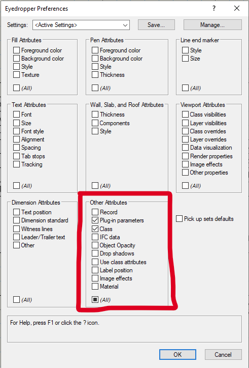
Hi everybody, I am trying to use the general eyedropper tool for circuits. As far as I understand I have to use the following tick marks. How can I adjust *which* plug-in data to pick up? obviously I don't want to copy the cable number for example. Thanks for any hints.
-
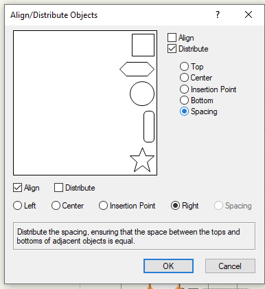
hi @markdd, thanks for the hint! unfortunately. Am using ConnectCAD, so it is a bit different. The Spotlight Tool seems to almost get me there. (Only works for same sized objects/devices, though). It's a start. 🙂 Thanks again. Best, George
-
Hello all, I would like to distribute devices with a fixed distance between them. Currently this seems to be determend by the outmost objects, but I don't have any control over the value? Or am I using the wrong tool? Thanks, George
-
ah, I see. embarassing. didn't notice. 🙈 thanks a lot Nikolay! 🙂
-
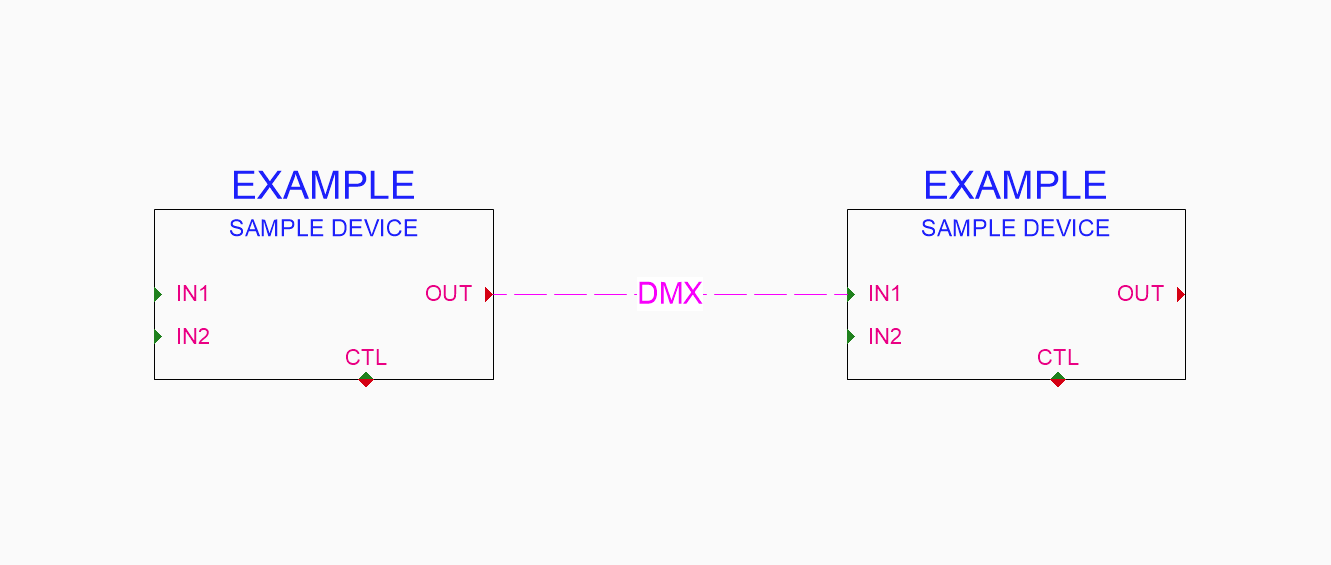
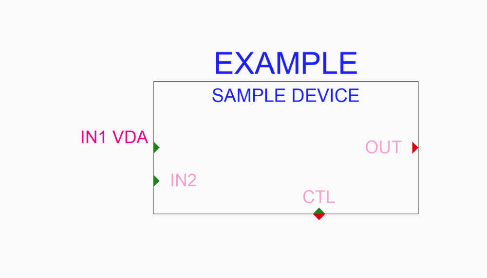
Hello all, to be able to hide certain port names, I created an extra class called PortNamesHidden and assigned it to one of the port symbols (skt_txt_vda_L in the attached file). Problem: I can hide/grey out the class PortNames (see screeshot), but I can not do the same with my newly created class PortNamesHidden and I don't really get why? What am I missing here? Thanks for any hints! Best, George 20220919_HiddenPorts_00.vwx
-
okay. so, basically: they took out a working feature for SP4 to implement it as a new feature in "some future" version? that makes sense. 🙂 I hope copy-and-pasting directly from Excel to a database list instead of having to go through a static list will be added by VW along the way? thanks for your help
-
hello, was wondering if it is possible to change the position and color of the circuit label text? currently I would like to have black text while keeping the circuit color the same. (some colors are better to read then others, so we'd like to have text display in black only.) thanks for any hints. best, george
-
wel, I had just sent a support request. thanks.
-
sorry, but where can I find that. Or was it supposed to say "Bug Submit form"?
-
Works in SP4 thanks
-
Hello @Pat Stanford, just updated to SP3 and it seems like the copy-paste-function was modified somehow and I can't copy paste a range of cells spanning multiple (adjecent) columns from a spreadsheet to the database subrows. It only works for multiple cells in a single column. (and if I understand this correctly, Copy-Paste directly from Excel into the database subrows still doesn't work) Is this another bug or this feature stripped? best, george
-
Best practice for setting up a project with multiple rooms/locations
elc replied to elc's topic in ConnectCAD
Hi @Mark Aceto depending on the amount of devices this sounds like a good approach. Another questions: is there a function for floors? Or are you just talking about the design layers that you use as floors? In your image you are using the room function on the schematic layer, right? As far as I know, this does not work with the room data attached to devices (schematic layer) only with equipment (in the rack elevation layer)? Or how did you set this up? Best, George