
Shane W
-
Posts
37 -
Joined
-
Last visited
Content Type
Profiles
Forums
Events
Articles
Marionette
Store
Everything posted by Shane W
-
Thanks. So (in theory) on a large site, if I was to start with Maximum Deviation (with only say 15cm) I would get the lines roughly where they were, and then I could go and do minimum distance to reduce the cont further.. The problem with using aerial drone surveying is that the trees trick the resulting contours so I'm trying to find ways to reduce the amount of time spent manually editing contours.
-
Hi @jeff prince I was wondering if you could explain what the difference is between simplify poly by "Maximum Deviation" vs "Minimum Distance" is? I've read the help description over and over but I'm still not completely sure what it's doing. So far minimum distance makes sense - I might for example want vertices no more than 1m apart.. but what about maximum deviation? When we're talking about a contour line, is going to move where the line is located? I have sites that are 50-150Ha but even on a small sub section of that, I want to ensure that where those lines are placed isn't deviating too much (or at all).. I've used Min distance before but (particularly with drone surveying) it results in loads of overlapping lines that takes hours to sort out, so I'm trying to find a more elegant way to speed up the workflow.
-
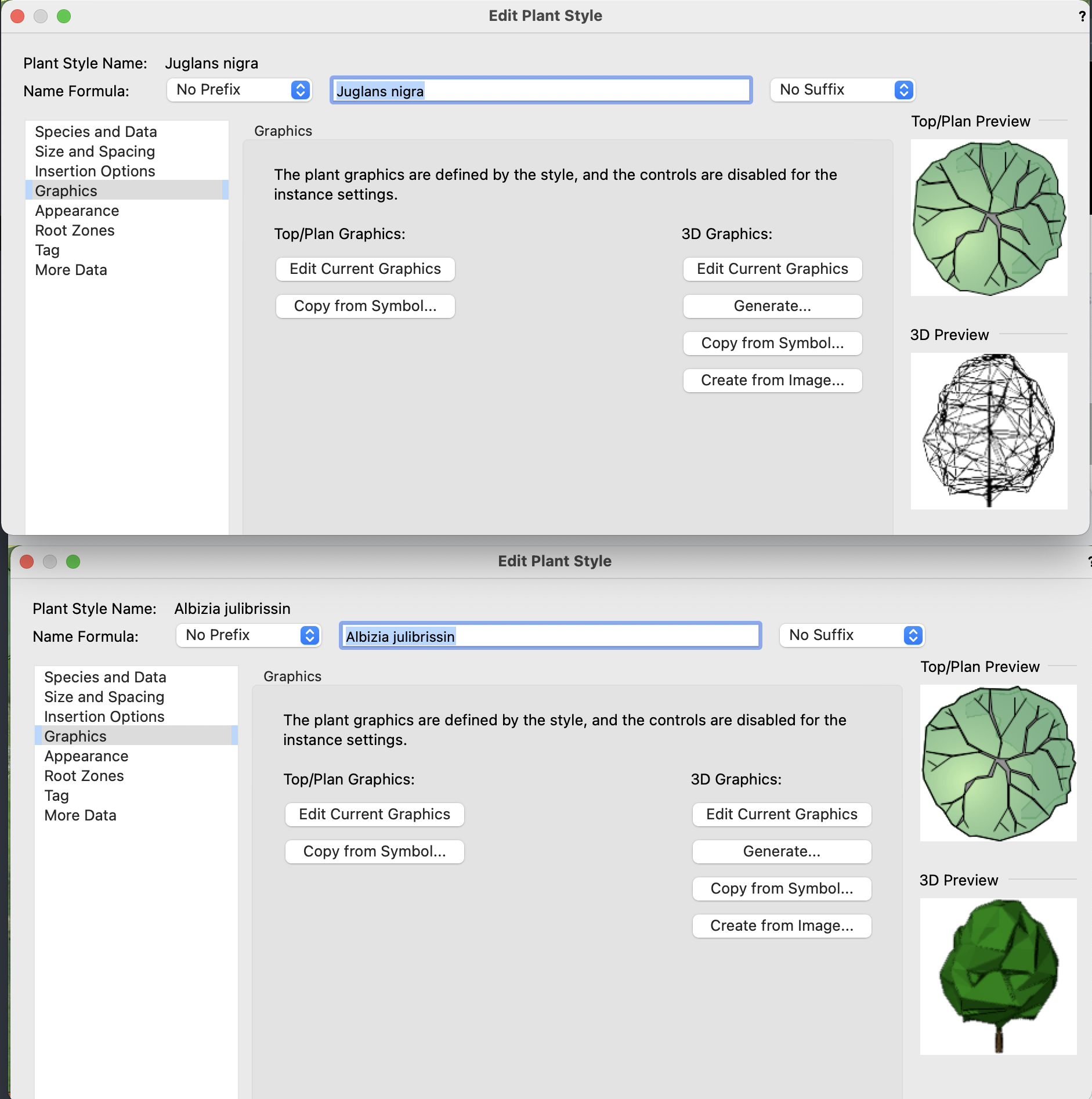
Thanks, I might have just found a workaround.. One thing I noticed is that if I imported the problem plants into a new file then edited the style, I could generate the 3D shell again.. Which is weird. I have imported the (now correctly generating 3D model) plant styles from the newly created document back into my project file (overwriting the existing ones) and it seems to reset them.. I'm still not sure what caused it, but that seems to allow me to move forwards.
-
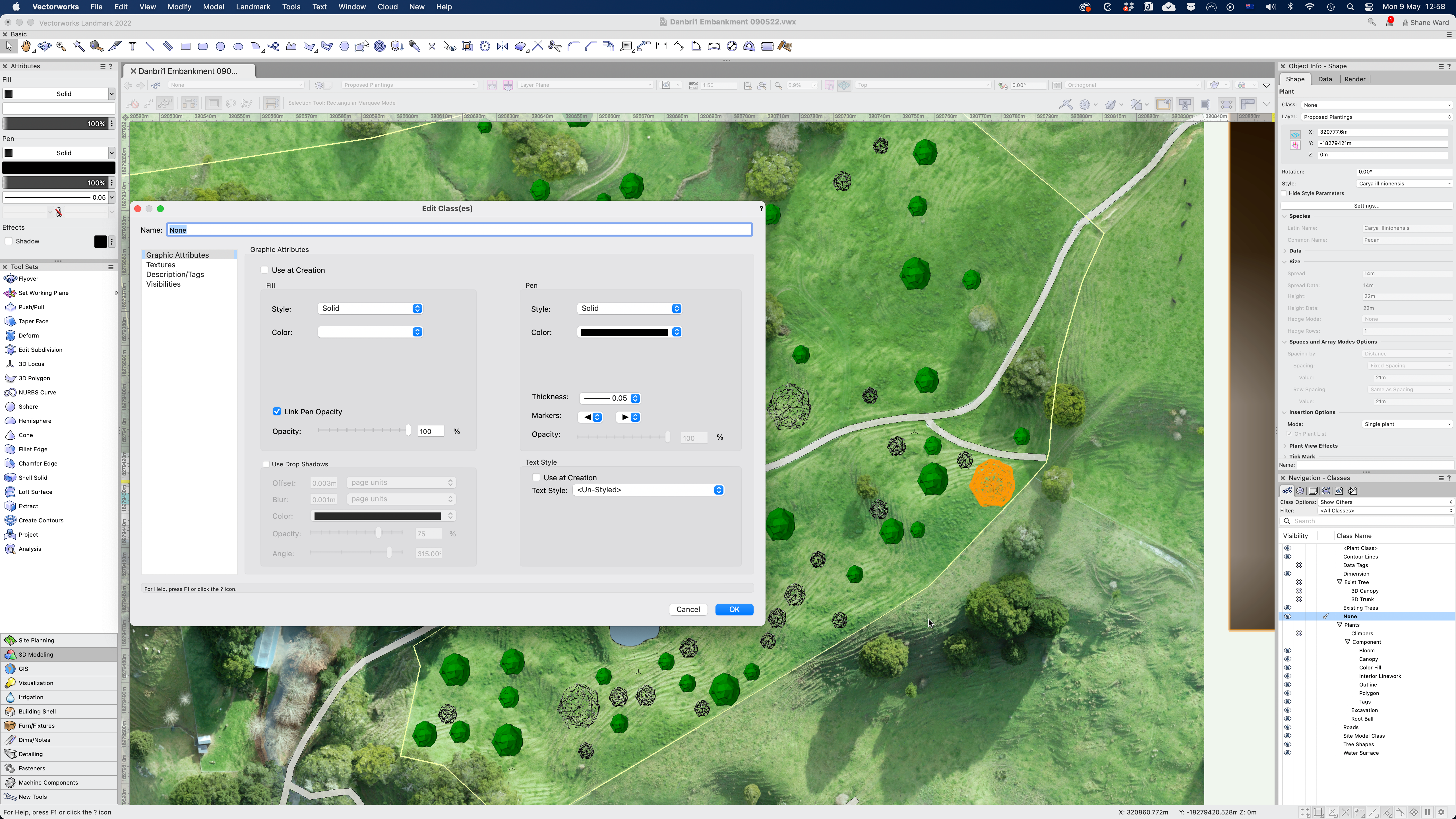
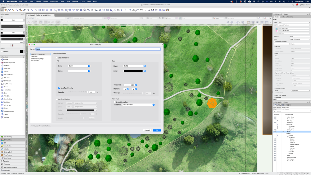
Thanks for responding @jeff prince. I'm still a bit confused as all of my proposed plants are set to class 'None' with Fill attributes as solid. Is there another setting I should look at? ..or should I move all those plants to another Class?
-
Hi, I was wondering if anyone could tell me what's going on. I'm using the plant tool, adding some new plants as I go.. and having no trouble using "Generate" in the Edit Plant Style > Graphics > 3D Graphics to create some models for the trees. ..until suddenly they no longer appear as normal shaded models, but instead only as wireframe. All the options (volume, shell etc are affected). I have no idea why. I didn't change any graphics/render settings. Now every time I go to set that, they only show as wireframes. I can view the previous ones I did as shaded models, but if I go to edit them they will only give me wireframe, so I have to cancel to back out. I can't see any 'setting' that makes them appear differently, and I tried closing and restarting to no avail. Has anyone had this before?

-
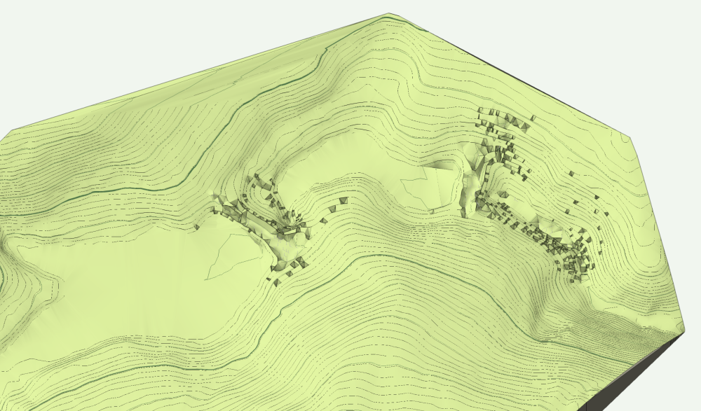
Shortly afterwards VW froze so I have to start again anyway.. ..but the stakes are the 'accurate' data, which I am importing because the contours (from 10yo LiDAR data) is "fine" but not sufficient really to get realistic cut & fill calculations for a contractor to quote on, nor (really) to generate an accurate detailed drawing of the modifications to be proposed... hence why I did the surveying ..with the intention of using those points to further refine the site model in specific areas where that detail would be helpful. I am noticing that in the area (left of centre) where there is a dam wall that the contours do seem high (as suggested by the survey points taken. While it's not going to solve my main issue, I am wondering if lowering the contour lines to match those points across the dam wall as a reference might help? .. Not that I know how to do that. 😉 The main issue (I think) is that the stake objects as site data are not being understood / treated correctly by Vectorworks in generating the site model.
-
@Tamsin Slatter I still need a bit of help with this.. For some context, what I'm trying to do is improve the accuracy of my site model which is built on 2013 LiDAR DEM data converted to 50 cm contours in QGIS, exported out as a Shapefile and then imported into Vectorworks to build a site model. So far so good. Then, when I take my survey points (which are centimetre-level accurate) and import them (also as a shapefile from points in QGIS) into VW, I can convert them to Stake Objects and Source Data.. but then when I paste them into the Site Model and exit.. I get this.. ..which is not what I expected. I would have thought it would re-draw the contours and site model to work those points in.. instead it seems to have just sunken holes wherever there was a point.. Any idea what's happening here?
-
Thanks for posting this Lisa. I'm working on areas of similar size and have been looking for an approach. (see other thread) I'm interested to know how you set this up.. so were you starting with polygons, converting them to landscape areas and then are you applying a Vectorworks texture to that?
-
Ah ha! 'Show other objects in editing mode' ..that was the magic. 😉
-
UPDATE: I have tried using the landscape area tool, but it seems to only be useable with the 3D style set to a solid. Image props (at that scale) makes VW grind to a halt. I'd be interested to know if anyone else has a different approach.
-
Hi Tamsin, I have this issue, so it's great to know that's how to solve it. Why does it create a bounding box like that?? Very strange. My problem with fixing is that I'm never seeing any data (contour lines) in the 'Edit Site Model Crop' window. Could you please explain your response: "trace around them and create a new polygon. Then, edit the crop, delete the original and replace it with your new crop object." Exactly what am I tracing where? In the 'Edit Site Model Crop' window I can't see anything other layers or data (such as property boundaries or other polygons etc). Would you be able to walk me through how to crop this model when I can't actually see it? Many thanks Shane
-
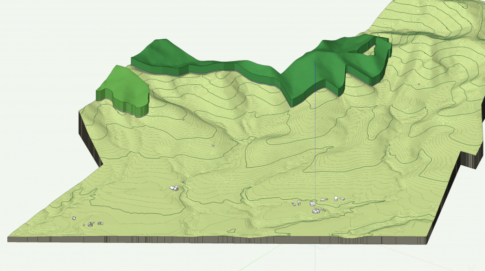
Hi, I was wondering what the best approach is when you are working in large areas and have existing forest patches you want to include in the design. The landscape area tool seems like it could work perhaps, but are there implications for taking this approach? I'm usually working on larger properties (50-160 Ha) and they have areas of exotic and native forest that are to be retained, but I don't want to waste time going through and adding individual trees or defining specific species mixes for these. Appreciate your guidance. Cheers! Shane