blanger
-
Posts
64 -
Joined
-
Last visited
Content Type
Profiles
Forums
Events
Articles
Marionette
Store
Everything posted by blanger
-
Link so I can upvote please 🥸
-

Less combined objects and better ways to connect them
blanger replied to Christiaan's question in Wishlist - Feature and Content Requests
I think I'm following now. I had this situation which was pretty annoying and could be solved by a revised approach. I had two walls that required different thickness both with the same finish. I needed 2 wall types, one for each thickness and then if I revised the finish I had to update it in both walls. -
I tried earlier today on VWX 2022 Service Pack 3... it didnt work until I got service pack 4. AND ITS GREAT!
-
Less combined objects and better ways to connect them
blanger replied to Christiaan's question in Wishlist - Feature and Content Requests
Please remember that architecture is not the only application. For set design purposes I often wish for more integration. For instance the ability to include base mould as a wall component would be a huge plus for Set Design. I'd say we work primarily with wall finishes and the flat itself is the simplest element. @Andy Broomell do you have any opinions on this? -
In case anyone is following along I found this great video by Jonathan Pickup that showed my how to Data Tag structural members. This is wonderful as it lets me pull the type of into my annotations - - too bad I used the individual 3d profiles instead of structural member tool. I wont make that mistake again (I wonder why the individual member tools even exist unless they predated the more complete structural member tool). This shows my beam pulling info from the object itself using a data tag with #StructuralMember#.#ProfileSize# and #StructuralMember#.#MemberID#
-
@Pat Stanford Is it further possible to put a number or letter in a field associated with each symbol and use a data tag to mark the symbols on a plan in viewport and include that number in the worksheet. I haven't successfully labeled symbols yet with data tags but I have big dreams!
-
Draw a rectangle at 75x200 and save as a symbol. Select "member type :custom" in the framing tool, scroll down to the bottom of the OIP. "Choose Profile Symbol" navigate in the resources that come up to your current open file where that symbol of 75x200 is and select it. 👍🏻
-
AHA! So Strange - Auto Hybrid then Group then Make Symbol if I want to insert in the wall. I always avoid grouping if I'm going to make a symbol to skip a step. Thanks!!!
-
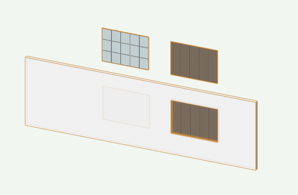
Son of Sailor! So the Auto-Hybrid Is relative to the axis for that object - I thought it was relative to 0 on my layers. Thanks for the fix - - you got me into this whole symbol in wall mess anyway!... Also you can see how I decided to make the window - pretty simple to do it as 2 extruded shapes rather than a bunch of extrude along paths. Thanks as always!!
-
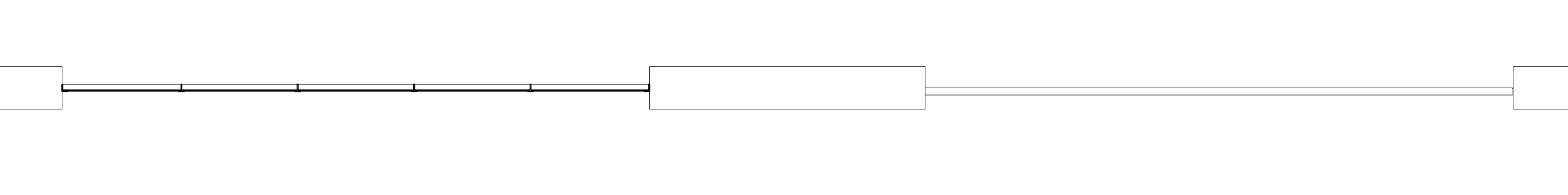
I'm banging my head against the wall! 2 Windows that I made into symbols. The one on the left I can get the Auto Hybrid to work and show me the muntins correctly. But the glass doesn't appear correctly and when placed in wall does not cut a hole in the wall in 3d. The one on the right has glazing that appears correctly and cuts the hole in wall in 3d but will not display correctly in plan. WHAT AM I DOING WRONG!!!??? I've already wasted too much time today on this 😞 Thanks! WindowTrouble.vwx

-
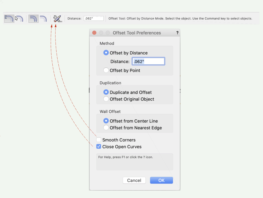
I love the offset tool... I love switching back and forth between "Close Open Curves" being off and on. I do not like going into the Offset Tool Preferences every time to toggle it. Please add this as a toggle button on the sub menu for the Offset Tool. (I don't use Smooth Corners really but maybe that belongs too) 🙂
-
Window and Door Tool maturity
blanger replied to Christiaan's question in Wishlist - Feature and Content Requests
What helps the most is knowing that you flow with different processes depending on time and situation. That in and off itself makes me feel better! I've done most of not all of the above methods and have been switching between them. Lately, in some fsds, I've even been turning off all layers after using the model section as a baseline to annotate over, seems like you do the same. Inspired by your door tutorial I just made my first few symbols to place in walls. I love it! Thank you!!!! -
Window and Door Tool maturity
blanger replied to Christiaan's question in Wishlist - Feature and Content Requests
@Andy Broomell Dream Crusher! I started to investigate windoor but that doesn't seem to have it either. Would you recommend building the whole thing and sectioning, or building with window tool and then drawing sections in 2D? -
Window and Door Tool maturity
blanger replied to Christiaan's question in Wishlist - Feature and Content Requests
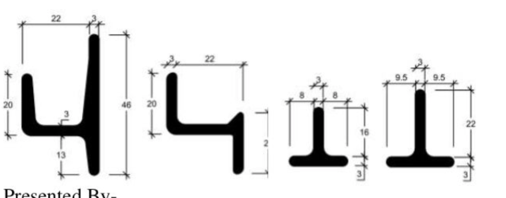
I'd love to be able to use typical steel profiles "T" Shaped Glazing Bar or Muntin, The Sash and the Frame so that when sectioning the profiles are correct. Coming to think of it, when I do wood windows I don't even get the ogee profiles of typical wood windows... so maybe Im reaching too far. 🙂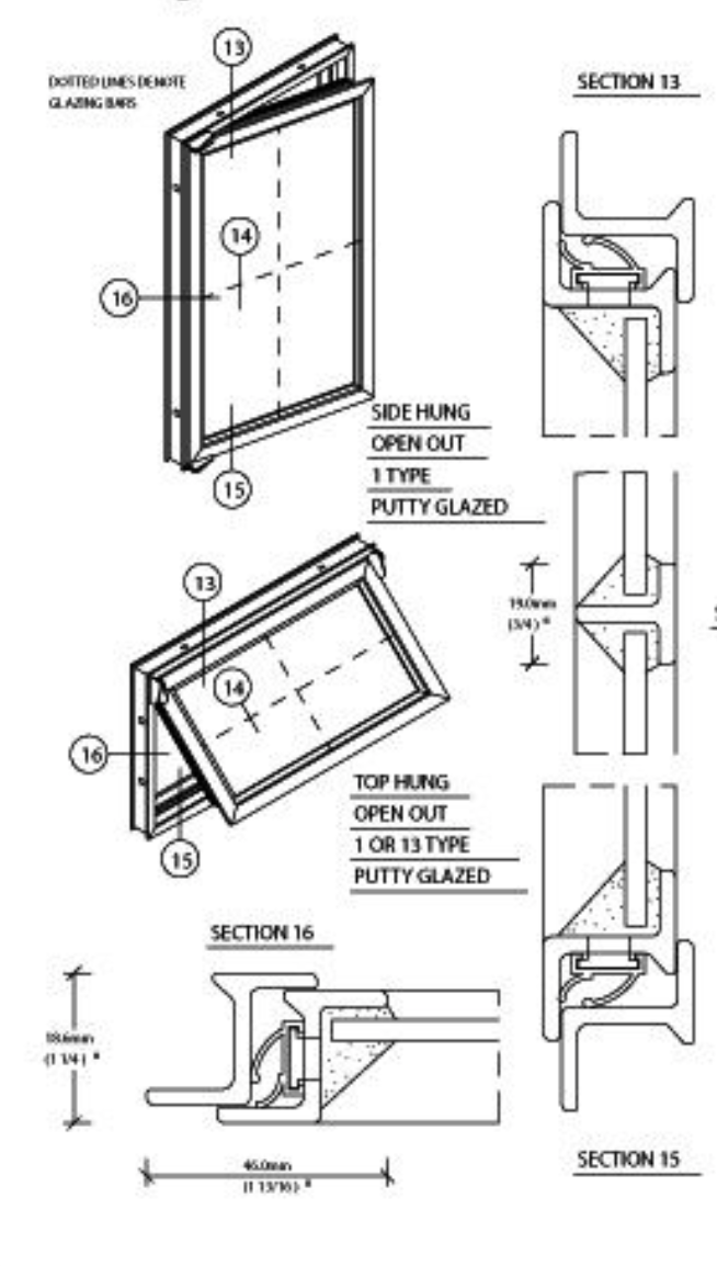
-
Window and Door Tool maturity
blanger replied to Christiaan's question in Wishlist - Feature and Content Requests
@Christiaan Do you have steel warehouse windows included somewhere in the wishlist for windows? I'd like to know before I make a wishlist item. 🧞♂️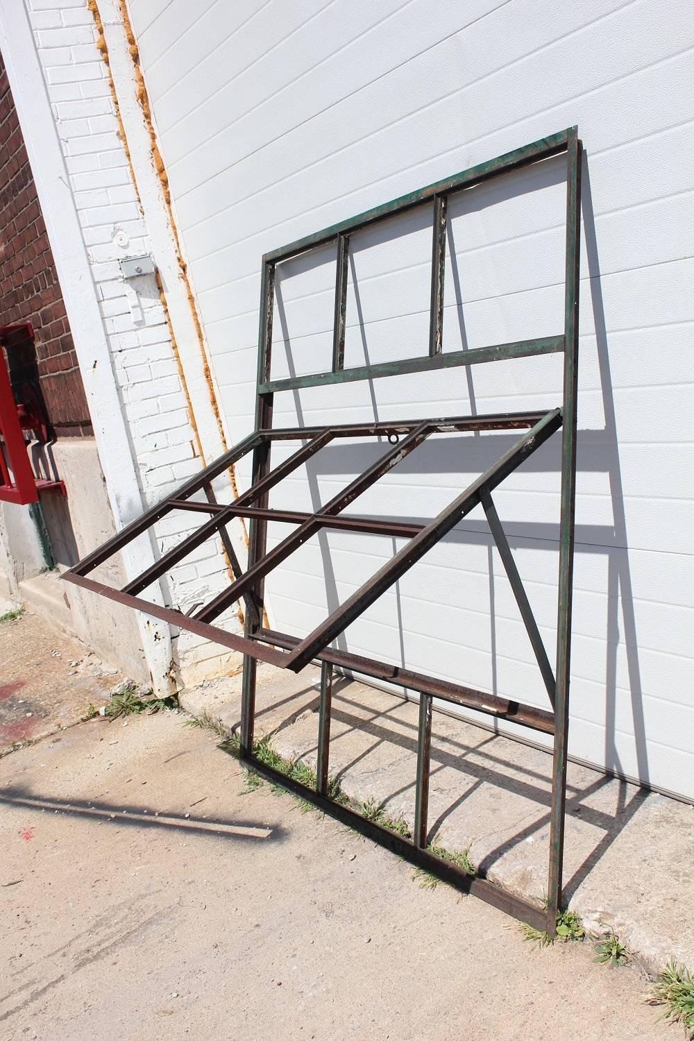
-
Brilliant! The scripted prospect is really interesting but since I don't work with steel as much this symbol approach is great because I will be able to apply it to all kinds of projects, like number of pistachios in a bowl... jk. Thank you so much!!! I appreciate you!
-
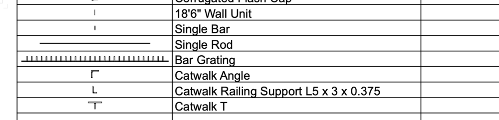
Pat - thank you for looking into this - I'm glad asked for help before falling in that rabbit hole. I will submit an enhancement request. I have an alternate idea I have for representing this information but could use your help. Concept: Make each member a symbol (which I've already done) and name the symbol - for instance - Walk Way Support W27x94 @ 65'-6" Create a worksheet showing those symbols names, image and qty. Use Date Visualization to color each symbol differently. Help needed: I can get it to summarize symbols in my worksheet but don't know how to A. include QTY of symbols in drawing B. restrict worksheet to only the symbols I care to display (perhaps by choosing only one class to include in worksheet) Any pointers you can give on making that work would be great. Just yesterday I learned how to make a window worksheet and I'm playing with other types of symbols now. Fun stuff!!!
-
Thanks Pat - I'm trying to shave off time from my documentation by using smarter modeling. This model uses 3D angles, round tube and I beams. I also just started reading that there may be a way to put the items in a worksheet if each are symbols with their symbol image, type, weight and length. I have a feeling the project with keep changing and having a ready to go schedule of parts would be amazing and save me lots of manual work. Attaching a sampling. Steel Members.vwx
-
I found this but still cant figure out what I'm doing!
-
Hi All - I'm new to tags and trying to use them to display info about two things - 1) Finishes. If I've created a wall and given it a material there are finishes embedded. I'd like to be able to create a label or call out with leader line with finish info for that wall generated by the material. Is this possible? It would save so much typing and ensure accuracy. 2) Steel Members. I'd like to have a label as a call out and leader line that will draw from the type of profile used to create the 3D steel unit, such as W27x94. thanks!
-
HELP! Trying to create a nurb between nurbs or line on face
blanger replied to blanger's topic in General Discussion
I just tried. • Extract top face • Lower to desired level • Click Analysis Tool in First Mode • Click on Extracted Face • Click on Main Object • Delete Extracted Face to Reveal Path. not bad!!! -
HELP! Trying to create a nurb between nurbs or line on face
blanger replied to blanger's topic in General Discussion
I wasn't able to convert to subdivision. I guess its harmless enough to post this piece. Thanks for looking! TestFile.vwx -
HELP! Trying to create a nurb between nurbs or line on face
blanger replied to blanger's topic in General Discussion
Its going to take me a moment to wrap my head around this!! Thank you! -
HELP! Trying to create a nurb between nurbs or line on face
blanger replied to blanger's topic in General Discussion
I haven't used the Analysis tool before. But the idea of lowering it is interesting. I even tried creating tubes with the top profile as the center of the diameter to get the line on the face but couldn't get all the shapes to subtract out to give me the lines. AHHHH. -
HELP! Trying to create a nurb between nurbs or line on face
blanger replied to blanger's topic in General Discussion
I really appreciate it - I will send privately as its an active project and that was just a portion as a "for instance."