

Shortnort
-
Posts
198 -
Joined
-
Last visited
Content Type
Profiles
Forums
Events
Articles
Marionette
Store
Everything posted by Shortnort
-
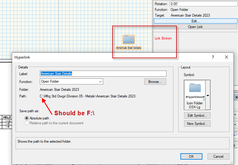
Can someone offer suggestions on why the link to drives other than C do not work?
-
GRAPHIC LEGENDS - ANNOTATIONS HUGE PROBLEM!!!
Shortnort replied to Shortnort's topic in Architecture
Thanks. I sure wish that I had been forwarned by VW of this most CRITICAL FACT. Hours have been lost redoing the notes. I now make back-up copies of my files on a regular basis. The autosave sometimes saves at the most inconvenient times. I think creating a symbol for each annotation is the simplest and safest way to catalog. Additionally, it will speed up the annotation process for similar frames, door types, etc. -
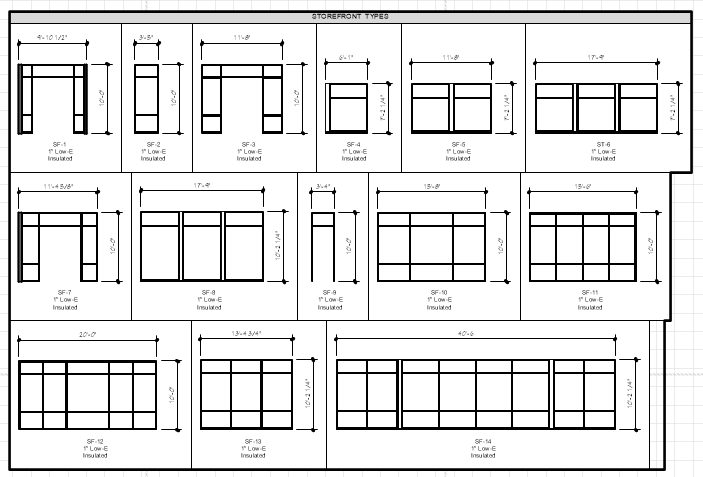
I have finally gotten somewhat of a handle on creating Graphic Legends. However, there is a MAJOR ISSUE that I have encountered: If you change parameters, such as add a line to the Description Title, offset of dimensions, etc. ALL ANNOTATIONS ARE DELETED!!! After the first time, I put them on a layer just for Graphics Legends, but POOF... Happened again. Is there a way to LOCK the Annotations to prevent this from happening. As you can see below, dimensioning the many frames is quite time consuming and to have that time destroyed simply by trying to fine tune the looks of the Legend is very maddening. My only thoughts at this time is to create a symbol of each group of annotations to be used as a backup in case of disaster.
-
For some reason the Hyperlink to "Open Folder" keeps inserting the wrong Path... I select the Folder in my F Drive, yet the Hyperlink keeps using C Drive. I have tried using both Absolute path and Relative path but neither corrects the problem.
-
How to create a Vicinity Map from an image file
Shortnort replied to Shortnort's topic in General Discussion
Tom - Thank you!!! You hit the nail on the head... Much appreciated. Image Resizing 03-24-2023.mp4 -
How to create a Vicinity Map from an image file
Shortnort replied to Shortnort's topic in General Discussion
I tried all of the above, but no luck... Image Resizing 03-24-2023.mp4 -
How to create a Vicinity Map from an image file
Shortnort replied to Shortnort's topic in General Discussion
rDesign: Thanks for the video!!! Makes perfect sense now - I was on the 1st mode... -
How to create a Vicinity Map from an image file
Shortnort replied to Shortnort's topic in General Discussion
Thanks. I will try the different layer suggestion. Grabbing the corners to rescale didn't work. I am not trying to have a site plan to scale. I am trying to have a vicinity map on my coversheet. -
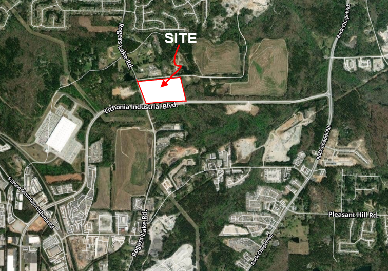
This is probably such a stupid question, but I am having a very difficult time creating a vicinity map to place on my Coversheet. How do you get it to scale? I have even created a symbol hoping that would work, to no avail, of course. Any suggestions is most appreciated.
-
Most States require Architects and Engineers to submit Comcheck Analysis to verify compliance with the International Energy Conservation Code. Comcheck is a program that is downloaded for the US Government. Each component of the building is input into the software for analysis and approval. Each component of each exterior elevation is input, as is roof, floor, skylights, etc. are also input. The exterior walls from floor level to the roof level are used. I was hoping that someone has come up with a way to do this with minimal drafting.

-
I guess there is no simple solution for this...
-
Fantastic... Thank you so much.
-
Thanks for the suggestions. Bart: Is it possible to explain the steps in creating multiple sheets as noted in your response? Otherwise, it seems that there is no "simple" method of incorporating the pdfs. Each of my projects has a minimum of 30 consultants' sheets - so adding importing and creating sheets is quite time consuming. It would be great if I could Publish/Issue a full set of documents within VW. I currently publish my Architectural sheets then combine other trades via PDF program into a Full Set.
-
Is there a way to have joist extensions for the open web joists? I have a lean-to canopy that needs the top members extend 16". I am currently just modeling and "attaching them to the ends.
-
Any suggestions on the best method for including consulting engineers' pdf files into the architectural set? It would be nice to have a simple method so that the drawing index could be generated automatically and a complete set issued seamlessly... Is it possible without spending hours importing pdf sheets and creating sheet layers?
-
As a workaround, I have created a new layer for Finishes. I created a walltype for FRP with a 4" base which is placed on the new layer. The only problem with this is that the door and window openings on the Design Layer do not break the wall. So, an opening must be placed into the wall. Perhaps someone knows how to create the wall breaks without inserting new ones?
-
I tried the 2 suggestions above. I did not have link walls turned on but the walls vanished as before. When I tried grouping the walls, the walls vanished and "The constraint is not valid" error occurred numerous times. However, it did finally group the walls and I was able to insert the FRP. After ungrouping the walls everything seemed to be okay. It seems that there should be a simpler solution to this issue.
-
Thanks so much!!! I will try those approaches.
-
Excellent suggestion. I didn't think about restricting the height in components. Let's say I need FRP on just a couple of the exterior walls. How do I start and stop the FRP without actually cutting the wall? The redline indicates walls to have FRP.
-
Excellent suggestion. I didn't think about restricting the height in components. Let's say I need FRP on just a couple of the exterior walls. How do I start and stop the FRP without actually cutting the wall? The redline indicates walls to have FRP.
-
How do you add 1/8" thick FRP panels to walls? I tried making wall types with them, but when there are set heights, such as 4', it gets messy when the walls clip to the roof above. I have tried creating a wall that is only 1/8" thick, but when I place the wall against a wall, when I hit an intersection, the original wall vanishes. So, I created an offset for the finish, but the same thing happens. It would be nice to automate the FRP panels, since all restrooms, etc. must have a minimum 4' high hard finish.
-
Top component? I created the opening using the windows styles in order to allow for various wall thicknesses.
-
I have created a symbol for a scupper cutout in exterior parapet walls. I works GREAT, except for one major issue that I can not seem to correct: The cutout is shown in plan views. How can the walls be displayed without the hole in the wall? I hope the answer is not to put the parapet wall on another layer - what a headache.
-
Is there a way to create a door style that has a frame with 2" jambs and 4" head? If not, what is the easiest way to create a frame that links to the door and schedule?

