


JHEarcht3
-
Posts
68 -
Joined
-
Last visited
Content Type
Profiles
Forums
Events
Articles
Marionette
Store
Everything posted by JHEarcht3
-
I tried it both ways : "2D & 3D" as the default setting, and "3D only" as an option. The latter did have 3D data for the contours. But the elevations were wrong, as noted in a reply above. I appreciate your help, and apologize for taking up so much of your time. I'm living on Social Security, and can't afford to buy a new subscription to VW. I'll keep fiddling with this project, as a learning exercise. But I may have to let someone else do the actual paying work.
-
Thanks. But the video seemed to have the sound turned off, and even at full-screen I couldn't read the dialog boxes (although the moving perspective text was readable) I saw enough to realize that your Import Tool has lots of options that mine doesn't.
-
I don't see anything in the VW2013 Site Model Settings to "preserve 3D objects". Why wouldn't the tool do that automatically? Maybe you have a later version with that option. I just imported the DWG file into a blank drawing, using the Import Survey tool. It had no setting for "preserve 3D". The file came in as a viewport, and when I went to the original it was at 1:1 scale. (see image Import Design Layer) When I selected a contour it had Z = 1.7'. So I scaled it by 240 to 1" = 240'. This time the contour labeled 495' had Z= 179.36'. So I gave up. I tried again, using the File/Import DWG tool, as I did originally. It reported that "file had bad data on line 1" and stopped. So, for now, I'll go back to the contours that I converted to 3D polys, and set manually. It will be very time consuming to find all the vertices on each contour, such as 495', with Z = 0. But maybe I'll at least have something to work with. I only have to fix the contours near the waterline. I'll still have to learn how to make it look like a real site with trees & such. BTW. These 3D glitches are the reason I stopped using VW2013 for perspectives, and used SketchUp instead. Now, I only have the free version of SU, so I can't do Site Models. That's why I'm trying to make VW work.

-
Is this what you meant by "OIP of site model"?

-
I never changed any vertices intentionally. I only selected each contour and gave it an elevation. When I discovered that some vertices were almost on top of each other (groups of five), I did delete a few. But that was only after the contour spikes were showing in perspective view. I was guessing that vertices too close together (fractions of an inch at 1 : 240 scale) might show up as spikes.
-
Yes, I can step through the hundreds of vertices individually. But why can't I set all at once, by simply giving the whole contour an elevation? Does VW have a Maxwell's demon, arbitrarily switching the elevation of random vertices?
-
I tried that. But when I converted the 3D contour to polygon, it became a group. When I converted back to 3D poly, it was a group of line segments instead of a contour. I didn't see a way to change it back to a 3D contour.
-
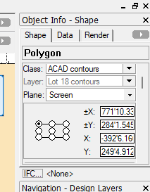
Since the imported contours had no elevation data, I selected each complete contour and gave it an elevation in the OIP. I just tried your suggestion, and found a few vertices with Z elevation of 0, and one was 243', while all others are 485'. How could this happen randomly, when the whole contour was set at 485'? Resetting vertices on just one contour was laborious. Checking the whole site is out of the question.
-
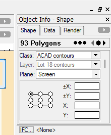
Here's a shot of the OIP with all the imported contours selected, before I made any changes. When I select a single contour, it has X & Y dims, but no Z elevation.
-
Images below show Original Survey with Viewport circled, and Viewport referenced onto a 24x36 sheet. The latter is what I imported into VW. I imported the survey into a blank document, without changing any VW settings; including "Convert Objects to 2D and 3D". It came in as a viewport at 1"-20' scale. The viewport had no 3D information. The contours were just polylines. So I went to the Design Layer, selected the contours, and pasted them on a new layer at 1: 1 scale. When I selected a contour, it had no Z dimension in the OIP. That's why I had to "ncessarily" convert to 3D polys and add the Z dimension manually. How did you import the survey with "contours correctly located"? Any idea why the 3D info was not included in my import? Am I missing something in the VW2013 Import DWG process? Is there another way to import a DWG file that will include 3D data? I don't have direct access to the surveyor.

-
How can I set the elevation of a single vertex on a contour?
-
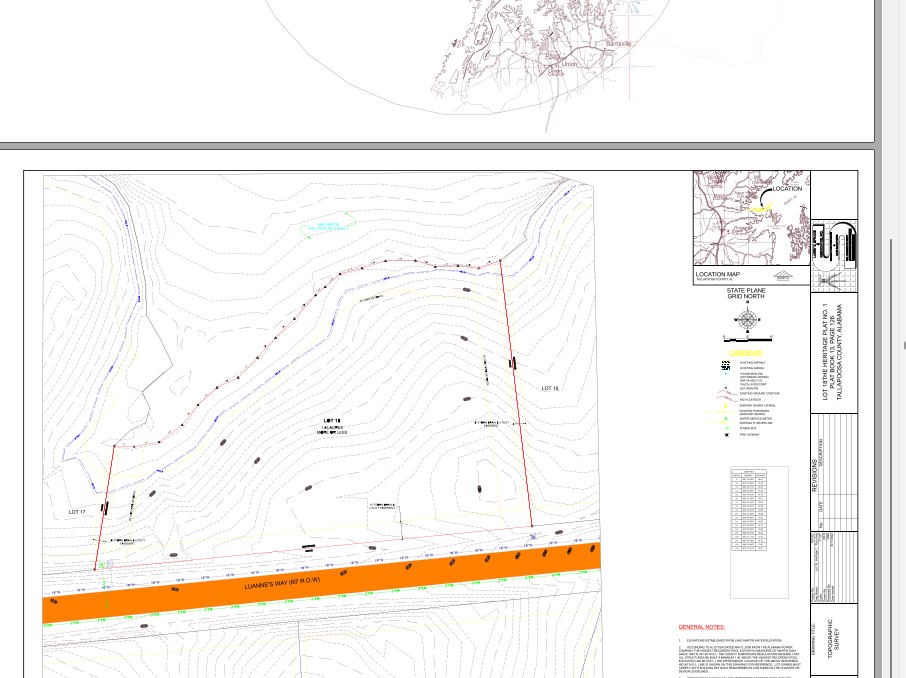
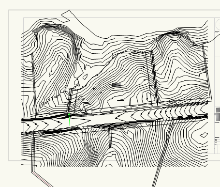
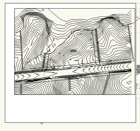
OK. I didn't want to take up so much of your time, but I'm going in circles. Here's the original Lot 18 site survey, which is a tiny portion (possibly a viewport) of a larger AutoCAD survey . And my site model, (trial 9) with only 2D and 3D contours showing. Lot 18 is the central portion of the whole area. I wanted to show where this project is on the general site. So I used the Property Line tool (in a different file), but in rendering it only showed the area inside the boundary. Is there a way to just draw lines on the 3D surface? You may notice other problems, such as very angular contours near the road (2' smoothing). Any suggestions will be appreciated. Lot 18, Heritage 1, 2011.dwg Lot 18 site plan --- 3D trial 9 -- 7-25.vwx

-
Thanks. I was hoping for a quick fix. But I now think I'll have to start over from scratch, with a clean survey. But I don't have direct access to the surveyor, and the architect is on vacation.
-
Benson, thanks for the reply. In VW2013 I selected the site model in both 2D and 3D views. But, in the OIP, I don't see any button or box labeled to "edit source data". Is there any other way to edit source data? The AutoCAD file I imported apparently didn't have an associated database. So all I have to work with is contour lines and elevation label text. I deleted the imported text labels, because they were wonky, and added my own. Which are turned off for the 3D model. Again, I can't find any tool to view or edit the source data. But the survey I imported was pretty simple, with only polyline contours and overlaid property lines. I have the PLs turned off. There are no roads or other artificial site improvements. So, the only extraneous objects I find are the bunched-up vertices in the polylines. I can select the whole contour, but not the individual vertices. So I assume all vertices are at the same elevation. When I select the whole site in 2D or 3D, the OIP reports "93 polygons", and no other objects, and no data. PS__I just tried to start from scratch, and use the Import Survey File into a new blank drawing. The command reported " Error : the file has bad data on line 1", and nothing was imported. I didn't use that command for the original import. Not a good way to start over! I may have to request a new cleaned-up survey file. But something seems to project a few of the vertices downward, mostly along the lower edge of the site, where a vertical face would normally be drawn. That face is added by the Create Site Model command. So, I have no control over it. The other (green) spikes seem to have flat surfaces. Could they also be artifacts of the Create SM command?

-
Pat, Thanks for the reply. My site is a small segment of a thousand acre lake survey. I had no contact with the surveyor. As I received it, the AutoCAD survey contours had no embedded elevation data, only contour text labels. So, in VW, I selected each contour and set the elevation manually in the Object Info box. Shouldn't that make all vertices on that contour at the same elevation? Is there any way I could select a single vertex to change its elevation? Validate 3D Data says "no problems found". I have found that some contours have vertices jammed on top of each other (about 10 - 20%). In 3D Reshape I see that they typically occur in groups of five or six vertex boxes. So, assuming that has something to do with the spikes, I have been laboriously deleting one of the 5 grouped vertices. That leaves behind a set of three. And if the three still seem too close together, I move one point farther away. At normal viewing scale, or at zoom, these deletions have no visible effect on the contour line. The Smoothing Interval is 2' on a 1" = 20' scale. Should I increase it? The contours look pretty jagged as is. See zoomed Image Multiple Vertices in Straight Lines. The triples indicate the clusters I'm talking about. Those tiny line segments seem to be superfluous in the middle of a long straight line. Where the blue boxes have black outlines, two more boxes are underneath. See zoomed Image Multiple Vertices for a typical group of five. It seems that whoever originally drew the contours was stuttering as he drew each curve. Or could the Vectorworks Create Site Model Tool be responsible for these glitches? Some of these clusters occur in the middle of a straight line, where there's no need for a vertex.


-
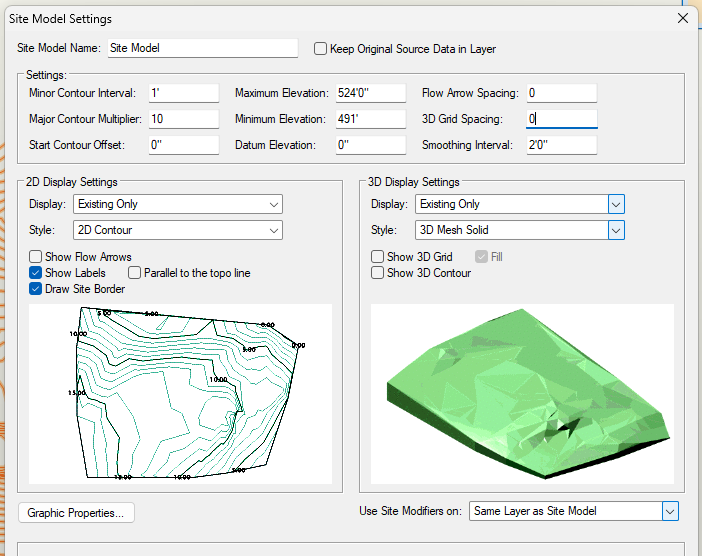
VectorWorks 2013 on Windows 11 on PC Learning to produce a site model (Settings image) from 2D survey contours (2D image). Survey had no elevation data, so I added elevations manually. Lots of repetitive redos before I got to this point. In 3D view the model was showing spikes along some contours (3D image). I selected each contour and using the 3D Reshape tool found some vertices that seemed to be too close or almost on top of each other. I moved them apart. That seemed to help, but I'm still getting unsightly spikes along some contours. What am I missing? I want the site surface to look solid, as in the Settings sample. So with all contours selected, in Obj Info Render, I selected "grass". Rendered perspective looks OK except for the spikes (Site Render image). The vertical brown face is below the waterline and minimum elevation. 3D Plan looks like (Image Plan Rendered). How can I make the brown areas look like water? Any suggestions will be appreciated.


-
Nevermind. Newbie mistake. I discovered that I had used an earlier 2D site with a few erroneously labeled contours that had been fixed in a later save. While fixing other glitches, I've made a lot of intermediate saves that come back to haunt me.
- 1 reply
-
- 1
-

-
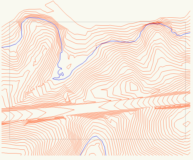
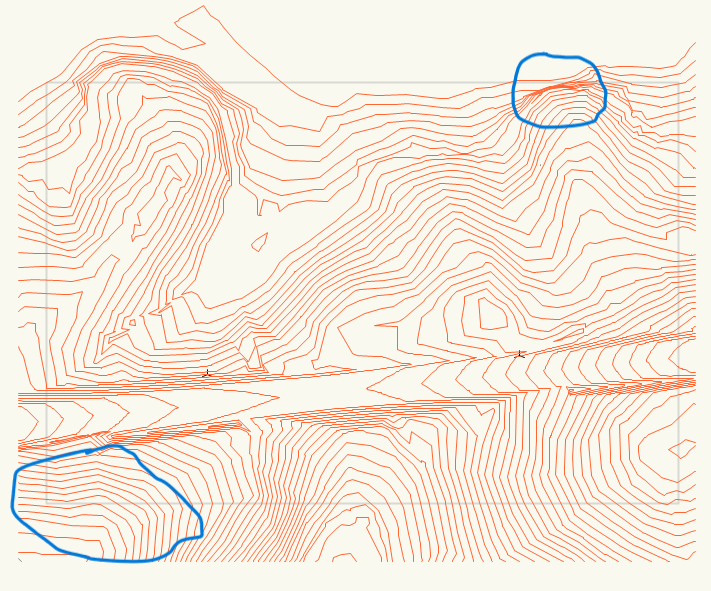
VectorWorks 2013 on Windows 11 Retired, but never did much 3D before. Tried one site model years ago, with little success. Now, have a side-gig project, specifically to create a site model for another Architect to put a house on. So, I'm a novice, learning how to produce a site model from scratch. The survey did not include encoded elevation data, so I added contour elevations manually. I'm using the outdated Create Site Model in the 2013 version. After cleaning up several glitches -- such as crossovers in the original -- I'm still getting overlaps, that make the 3D model look wonky. Image "Site overlaps 3" shows duplicate contours within contours. Those extra 3D contours are not visible in the 2D site. So I don't know where they are coming from. Image "Site Model contour overlaps" has the glitchy areas circled. The Create Site Model tool seems to be adding some unnecessary contours. The question is "why", and "what can I do to remove them?"

-
Johnathan Thanks, that worked.
-
VW 2013 on Windows 11 Retired & out of practice. I need to trim around a survey contour map to make it fit on the border sheet. I've tried the Trim & Clip tools, but my outdated software doesn't have some of the newer functions for multiple operations. I've had this problem before, but don't remember what the workaround is. The workaround in the photos is to overlay a white 2D surface with cutout. When I place a surface over the lines and click "Clip Surface" the error says "must be in same plane", even though it's all 2D and inside a group. Eventually, I need to do a 3D rendering, so overlay or Clip Surface won't do the job. Any ideas?
-
Thanks, but I'm retired and don't do enough drafting work to make a subscription economically feasible. VW 2013 is still running smooth, even with 100,000 miles on the odometer. I now have a DWG 2011 file, and it imported into VW2013 with no problems. I was confused by the wording of the error message. Its meaning is now obvious.
-
Thanks. I'm waiting for a new file. With fingers crossed.
-
Thanks for the suggestion. The sender uses Microstation, but I don't know the operating system. One filename does have a symbol in it : "&". But the one I'm trying to import only has commas : Lot 18, Heritage 1, Topo. Win 11 shouldn't have a problem with that filename, right? Besides, the error refers to AutoCAD version, not the filename. The original file is located on the desktop.
-
My old creaky VW runs smoothly in Win 11, except for importing DWG files. I also got "teigha" errors back when I was running on Win 10. Do you have any suggestions for importing DWG site contours into a VW file for a 3D drawing? I'll eventually have to export back into DWG. Is there a way to convert 2011 DWG into something I can use?
-
VectorWorks 2013 on Windows 11 I'm long retired, and only do a few small projects a year. Hence the outdated version of VW. Today, I tried to import a contour survey in DWG format. The error message seems to be contradictory : It says the file is 2011 version, and that VW can only open DWG files up to 2013. I have already requested a new file in an older version. But shouldn't VW 2013 open a 2011 file without an erroneous error message (image attached)? I'll appreciate any enlightenment.
