


station
-
Posts
56 -
Joined
-
Last visited
Content Type
Profiles
Forums
Events
Articles
Marionette
Store
Everything posted by station
-
i've had that issue as well but not recently - this is different and happens in copying in both iso or plan views. Waiting to see if it re-occurs in 2022
-
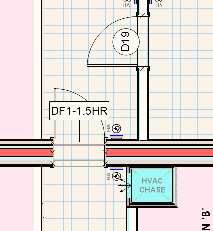
Hi this issue seems to be continued in 2022 - commented on previously no responses symbol of a floor layout prior to editing a door - editing the symbol and making a change in the door OIP plan is still considered a top/plan view? Have to exit symbol and re-enter to continue editing - is getting tiresome. Is there something obvious (or not) that I am missing? thanks john
-
just went to plot a project and on a stairwell section (6 stories) was amused (not) to find the stairs had gathered together on the 3rd floor for an impromptu party. stairs were properly on their layer but had shifted in Z either up or down. Visually was humorous in section but had to insist they stay on their floor in the OIP but had to retype a few times. On a 6 story building with a few stairwells this gets time consuming. I typically configure a staircase on the main floor and copy and pip to successive floors (adjusting the landing floors in the OIP as needed). Its gotten to where I will do this in an iso view to ensure they land where they are supposed to. Is there something in this to imbed the error? thanks
-
this is definitely a bug - asked the question recently but no responses. Editing within a symbol of a suite - editing a door - the plan switches to a 3d plan plan view (or a mixture of both). Also a big lag in editing time - but that seems typical of working within symbols (this is 2021) - if you hover over the 3d door a ghost of the 2d plan is there anyone else had this issue? thanks
-
HI - yes the bubble handle and line will align with the crop border (top and bottom) then the 'shoulder length' setting in OIP will either align it to the crop (set at '0' or raise it above however much you want. I discovered the end position does work but only if you use a bubble at the end position - in a viewport the line length (at bottom) can only be controlled by the crop - hope that makes sense
-
with 2021 I found it best to not edit lengths or position of gridlines in viewports by reshaping but by using OIP and viewport crop. Viewport crop repositions bubbles within the viewport. Adjusting start positions within the OIP seems to work but end positions don't seem to adjust. gapping the line is just a matter of editing what that line is (lineweight is a good suggestion). Tool in 2021 has been a bit erratic (changing heights in viewport for no apparent reasons) - just about to try 2022 so looking forward to improvement
-
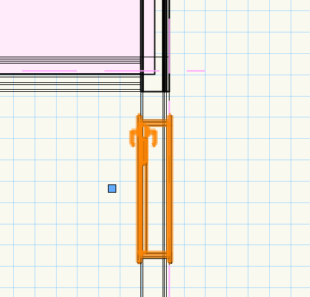
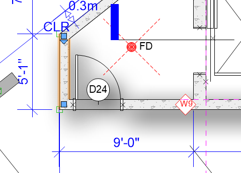
editing 2d - symbol changing to plan or 3d view erratically
station posted a question in Troubleshooting
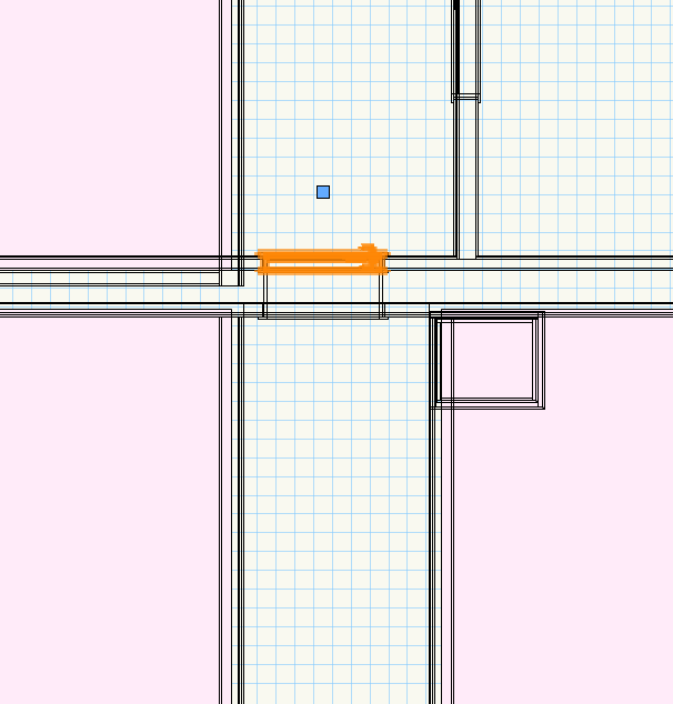
having a problem with a new drawing where; when editing a symbol in 2d view the view changes to a plan or 3d plan view - below shows when flipping a door opening it defaults to 3d plan
-
Hi I have a curtainwall detail as a symbol within a wall and is an autohybrid within the symbol - symbol is in one wall on its own layer (with a 4story layer wall height). Glazing is tapered but can't get it to display on floor plans at anything other than its initial cut plane - would like to show the glazing taper as it shows up on each level. I am not following any proper methodology on this - but options for cutting elevations seem limited (not using stories) - winging it but happy to hear any suggestions
-
Had an interesting experience where viewports went blank with an open gl render (fine in hidden and rendered). Also was not able to work in both wireframe or open gl on a 3d model in layers. Previous version of the file was fine and subsequent changes were model changes (walls symbols moved, etc.). Did the usual, reboots, changing vw open gl preferences, etc. - then given the revisions I started looking for orphan objects which seems to be a source of lot of vw problems...and that was it - a symbol that decided to run away from home and was located a few miles away. Safe and sound but definitely screwed up my working day - about on par with my dog. So the question is why do symbols run away and could be a question for a software psychologist - do they not feel part of the software family, alienated kind of thing? What can be done to make them behave?
- 1 reply
-
- 1
-

-
that does work identically and can maintain class visibilities if they are consistent - just swap out the layer. If you have different class visibilities in a layer though pasting the callout in the layer carries the class visibility to the viewport.
-
I've used objects turned to hybrid then converted to a symbol placed in walls or in the drawing. If it is complex to edit and just want to look at the symbol - will often put it in another file and import it back. Similar to editing a selection group in Revit. Editing the components doesn't disturb the placement. It is true that it is easy to nudge objects out of place in VW. If I have something complex i am editing i will also generally make a copy on the clipboard to paste back in place just in case. A lot of VW functions just don't 'undo'. Lock function is great but I hate the heavy grey line. I use a class function (greyed) to lock key components sometimes. Would be nice to have a selection group that can be isolated for editing.
-
if its a stacked viewport (like for different floors) I create the original viewport on a design layer (as a callout usually) and then copy and paste to the other design layer levels - it will come up with the option to 'create viewport in the Object Info. and it will create a viewport of identical size - you subsequently have the option to create instances of the callout in any other viewport If you just want the viewport crops to be identical sizes - it is just a rectangle so create one size and in each viewport crop paste it in hope that is what you were looking for. john
-
thanks @Nikolay Zhelyazkov - great to have a solution for publishing (figured there was some setting somewhere controlling visibility). As for workflow - for a tag to be functional it has to be attached to the object (wall in this case) and the wall is in a symbol so no real options there other than exploding them and creating a block outside the symbol or what I do is have an unassigned tag that I place over the symbol and type in the data. In viewport sections I find the wall tags don't always recognize the wall so stopped using them and use an unassigned thanks again. john
-
Hi did a search and no questions or comments since 2012 on using speech commands. I find I am getting bogged down with keyboard also getting lonely with covid - figure I can at least talk to my computer. Is anyone successfully using dragon. Would love to hear your experience before purchasing. thanks john
-
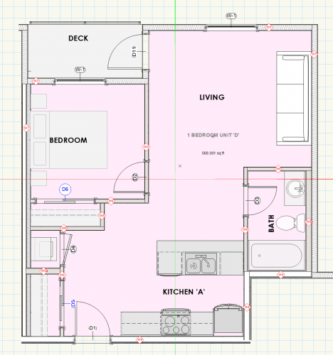
Hi Nikolay sorry for the delay - appreciate you interest. As no one else has complained am hoping it is operator error... I pasted a unit symbol w/ wall tags and a space into a new file. When you open the file you may or may not see wall tags or a space description . Should look like the screen shot (though door tags went crazy) If not edit the symbol paste in a new tag and select all (18 wall tags will be listed - hit the scale text and uncheck and recheck and they will all appear (also if you hit other options). Go to publish the sheet and they will all disappear again or will randomly disappear at any point or from some walls and not others. Ditto with the space and door tags change size. With the space tag it reappears if you modify any description. Am hoping to find some time to create my own tag to see if it is more stable but as it applies any symbol within the symbol didn't feel too optimistic thanks John .SAMPLE SYMBOL.vwx
-
I would love an answer on this. Wall tags within symbols disappearing upon publishing??? Once again I've had to go through an entire project xploding tags within symbols to groups to get them visible in publishing. These are 'smart object' that I have to lobotomize - its criminal.
-
I would be more tempted to use it for custom residential which I used to do as well - Johathan Pickup's video on this thread is a good source for that and organizing for it. The control of being able to set heights for everything from exterior slabs to bsbd heights, electrical, etc. would be great. Revit had a lot of functionality for adjusting those things but was still quite manual.
-
walls will not read layer wall heights in symbols they just flatten to 0 - what I have found is that wall height has to be set to layer elevation and then told what to be within the symbol (8' or whatever). Currently this works for me as most of the multi-family projects I work on are set framing spaces btwn floors - and provides me with a working 3d model and produces pretty clean sections and elevations. I am more likely to alter the layout of an apartment than floor to clng heights. So it works well for multistory including all exterior walls. I create symbols of each floor as well containing the unit symbols. So can change overall unit dimensions and a floor layout once as opposed to a lot of copy and paste. I am sure that a wall parameter within a symbol could take instruction from the container like a story and with some wall types it seems to work??? but then blows up. will have to play with it again and see what the behaviour is. Just haven't had time to explore more - what I have been doing seems to work which is often the best you can do. What I don't like is data tags like wall tags (symbols within symbols) go wild - disappear, change scale etc so become useless and at some point have to be exploded to publish.
-
true and the examples blur on both sides of the wall (which can be finetuned and height can probably be better approximated - it is just a fast way). I like Alan W's approach and works well for siteplans
-
this is just simple plan viewport (wireframe) where I enabled shadows on the walls in the layers. You can adjust the angles, blur, colour and offset. It doesn't affect crispness of the linework
-
Hi Jonathan - yes I have been a fan you have definitely made the transition from Revit to VWX much more pleasant, thank you!. Your video made stories very simple to adopt if it wasn't for the walls in symbols issues. I did some hybrid where I used stories but had to duplicate wall types to work within symbols and then within stories. I will try again as it is definitely a plus for foundation and roof and keeping organized. thanks john
-
revit gets pretty complex as well in making level changes especially when levels contain associated objects like plenums or blocks that are not constrained. But it can be done graphically using dimension strings if everything is set up properly. The computing time is insane and subject to crashes. Your suggestion of creating a 'default' level in stories that can be propagated up and then 'special' level i think is perfect. Changes (like ceiling plenum) in the default would then just change. 'Special' is then just special. As for metric and imperial I have to bounce back and forth all the time (code and construction) and you have to really check that VW has actually made the dimension string changes. Have been embarrassed a few times with publishing a half/half metric/imperial.
-
too funny - i was excited about stories - felt like getting a new car to test drive but couldn't get it out of 2nd gear. Construction analogy would be cutting a board twice and it is still too short.
-
I do agree and would love to use it if walls functioned within symbols within stories. I did have a project where they changed the floor assembly and its not bad to change layer elevations but it was a PIA to go into each symbol and adjust wall heights. Symbols can be story bound and it worked 80% or so -
-
I am also an ex-revit user having to work in vectorworks. Initially I was keen on utilizing the story setup but subsequently had issues with wall types bound to stories in symbols (behaving erratically ). Probably user error but simply using layer elevation and wall heights I could get consistent wall behavior within symbols and converting units and floors to units is critical for me. Note that for a wall within a symbol to work - height is set at layer elevation and then given a height manually.


