Anders Blomberg
-
Posts
196 -
Joined
-
Last visited
Content Type
Profiles
Forums
Events
Articles
Marionette
Store
Everything posted by Anders Blomberg
-

GRAPHIC LEGEND - Material Description, Mark, Keynote ...
Anders Blomberg replied to drelARCH's topic in General Discussion
What a weird thing, I added text to only a few of the material marks to try it out but my legend doesn't return anything in any of the cells in the legend, whether they have something in the mark field or not. Looks as below. But you get the mark field for the materials where the mark is present?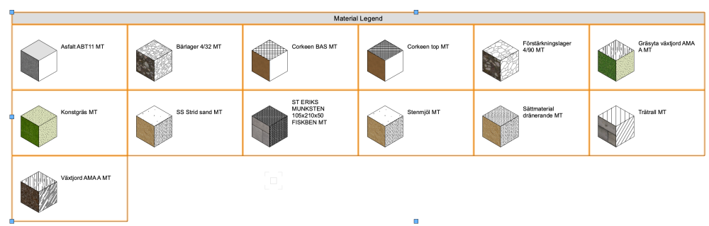
-
@inikolova @Dave Donley just a question out of curiosity; is there a reason why minor bug-fixes like this can’t be released between the larger SPs at set dates? Just as soon as they are discovered and fixed? Even a month or two can be a very long time to wait when project deadlines are set.
-
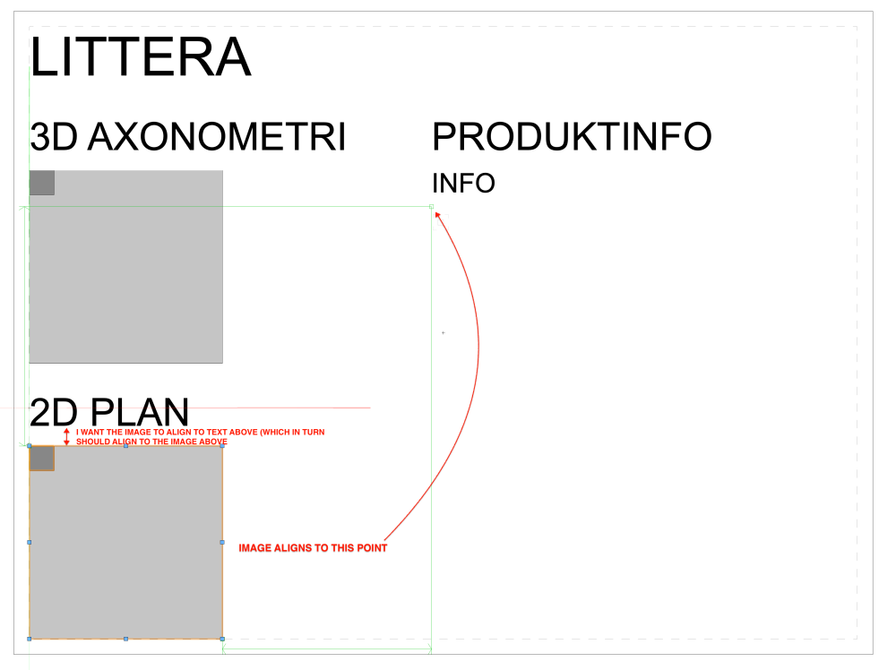
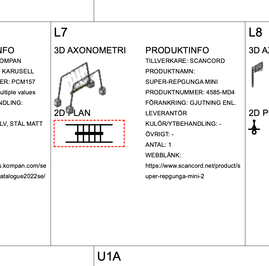
@Tim C. I love this new graphic legend tool, saves me so much time. But I'm struggling with the alignment between objects. I attach an example below. The images varies in size so I use auto align as I want some relations to be more constant. But I can't get the alignments to align as I want them. Is there a way to control what aligns to what? Currently the alignments seems unpredictable when having a couple of different objects in the cell. Resulting cell where text and image overlap:
-
GRAPHIC LEGEND - Material Description, Mark, Keynote ...
Anders Blomberg replied to drelARCH's topic in General Discussion
2023 SP3. -
GRAPHIC LEGEND - Material Description, Mark, Keynote ...
Anders Blomberg replied to drelARCH's topic in General Discussion
Thanks @Pat Stanford. No luck for me with this one though. I use the exact phrase in your screenshot but get nothing at all out of it. Am I supposed to modify the text somehow? This one works for both attributes and objects? On a side note, I find this type of workflow a little to much coding-esque for my knowledge. Is it possible to get the same result in more of a clicking on stuff-workflow? -
GRAPHIC LEGEND - Material Description, Mark, Keynote ...
Anders Blomberg replied to drelARCH's topic in General Discussion
I'm very much interested in the same! I noticed in a short presentation of the tool that they had a legend with some additional properties added to cells so I guess it's possible?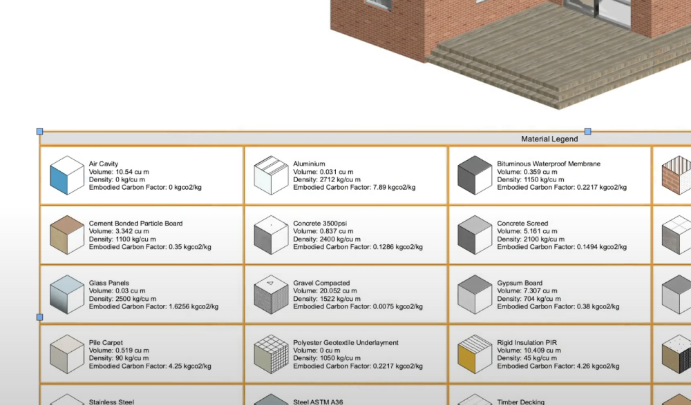
- 26 replies
-
- 1
-

-
- graphic legend
- material
- (and 1 more)
-
How weird, seems beyond my level. Got it sorted with a round node as suggested though and it works fine.
-
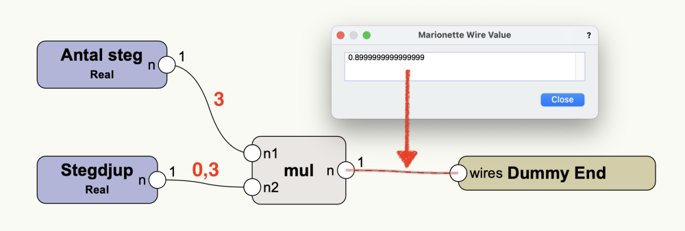
I'm a little confused over some simple math numbers I'm getting with marionette, see below. To me, 3x0,3 should equal to exactly 0,9. Why am I getting another number?
-
Site Modifier Transversal Profile V.2023
Anders Blomberg replied to jpccrodrigues's topic in Site Design
@jpccrodrigues Did you try to relocate the internal origin close to the geometry rather than moving the geometry to the origin? Setting an internal origin allows you to keep the georefed origin, it's how I set up all my models, otherwise I run into all sorts of weird issues. -
Thank's! I'll give it a try. I'm using Sublime because a programmer friend recommended it but haven't looked at other solutions yet. Might try PyCharm as well!
-
I’ve taken up a Python class to try and do some scripting for VW on my own. So I’m very much a total rookie in this. I use Sublime as IDE on my mac and want to use the intelli-sense for VW as described here. But I can’t figure out how make us of the file File:Vs.zip so that Sublime picks it up, anyone here that could point me in the right direction?
-
Thanks for confirming! I’ll wait for the next update then.
-
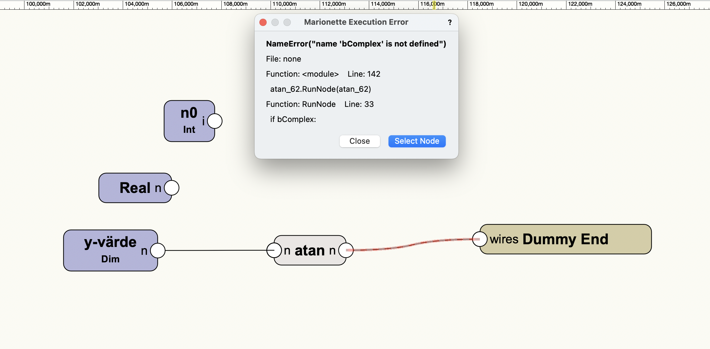
I'm building a network and am trying to use a "atan"-node. It seems however that whatever I try I can't get a proper output from the node. I tried feeding it with both int, real and dim numbers, but always get the same error, as shown below. I brought in a math friend and he believes there might be an error in the code, specifically a part called bComplex, but we don't know how to edit the node so we couldn't try our hypothesis. Anyone know if there is a bug in the atan node or if I'm missing something? @Marissa Farrell perhaps?

-
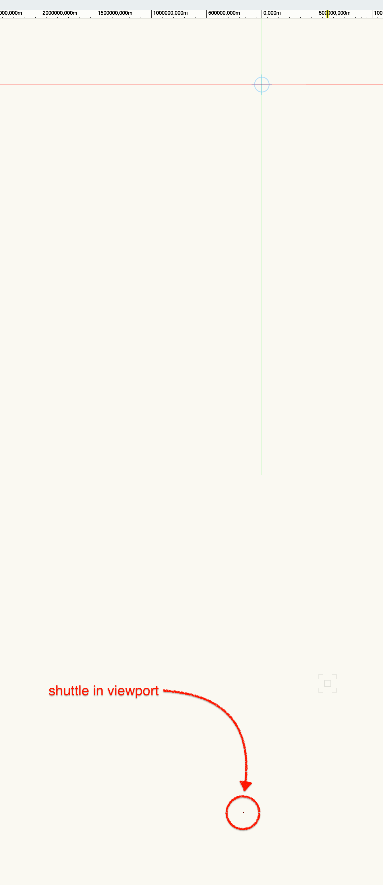
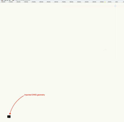
I seem to always struggle with georeferencing no matter how much I work with it 🙂 This time around the fault might actually be within VW 23 though but I just wanted to check with the forum first. I start out with 2 copies of the same file, both set up with the same/correct georeferencing settings. I have received a georeferenced DWG that I've imported into one of the files to create a shuttle file. The imported geometry sits right where it's supposed. The other file is intended as the master file, so I create a viewport for the shuttle file. This time around the geometry is way way of location, roughly by half a globe. Did the same thing in 2022 and here the geometry sits in the right location in both files. I know 23 has some GIS/referencing updates, so maybe my workflow is incorrect? I attach some screenshots and the two files. NBK NY = shuttle, Björkhaga = master. Might I call upon @Katarina Ollikainen for some help again? Björkhaga.vwx NBK NY.vwx

-
Generating polyline contours at specific height?
Anders Blomberg replied to lisagravy's topic in Site Design
Nice, I believe the triangulation of DTMs are simplified in 2023, might be the reason. I'll give it a go later. -
@Samuel Derenboim Great stuff! Thanks for letting us know. I will try this out as soon as I get a chance. Currently I'm transitioning these types of drawings to the new Graphic Legend tool, looks to be one of the really great features of 2023. As the tool still uses the same way to fetch data it would be hugely helpful if I could make this work as you describe. I actually picked up a Python course just to try and learn how to do this as I figured an IF statement might work but never understood how 🙂
-
Danish Vectorworks user wins award...
Anders Blomberg replied to John S. Hansen's topic in General Discussion
Inspiring stuff! Will this go into production as a product? Storm water management is often a big issue in my projects and regulations are really tightening up in this area in Sweden.- 3 replies
-
- 1
-
-
- awards
- sustainability
- (and 3 more)
-
2023 is out for Service Select Members
Anders Blomberg replied to Wesley Burrows's topic in General Discussion
Really hoping for the new grading options to be the game changers I've been told they will be! Looks promising! -
Generating polyline contours at specific height?
Anders Blomberg replied to lisagravy's topic in Site Design
Dug up this from the past and the subtraction has been working nicely but all of a sudden stopped. @Benson Shaw, would you mind having a look at the attached file and see if you get the same issue? Subtract issue.vwx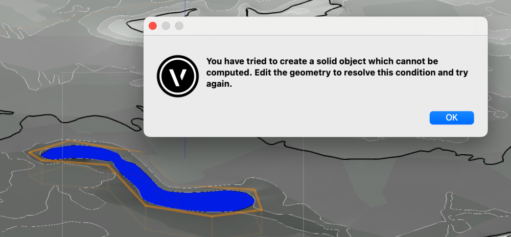
-
Getting a worksheet to return the 2D attribute of an object.
Anders Blomberg replied to NFULL's topic in General Discussion
Agreed on the need for this. Did you come to a solution @NFULL? -
@Nikolay Zhelyazkov Works like a charm for me, thanks for remembering this thread and getting back to us! Now if I could only click the component instead of defining it in the tag definition, a wish for the future.
-
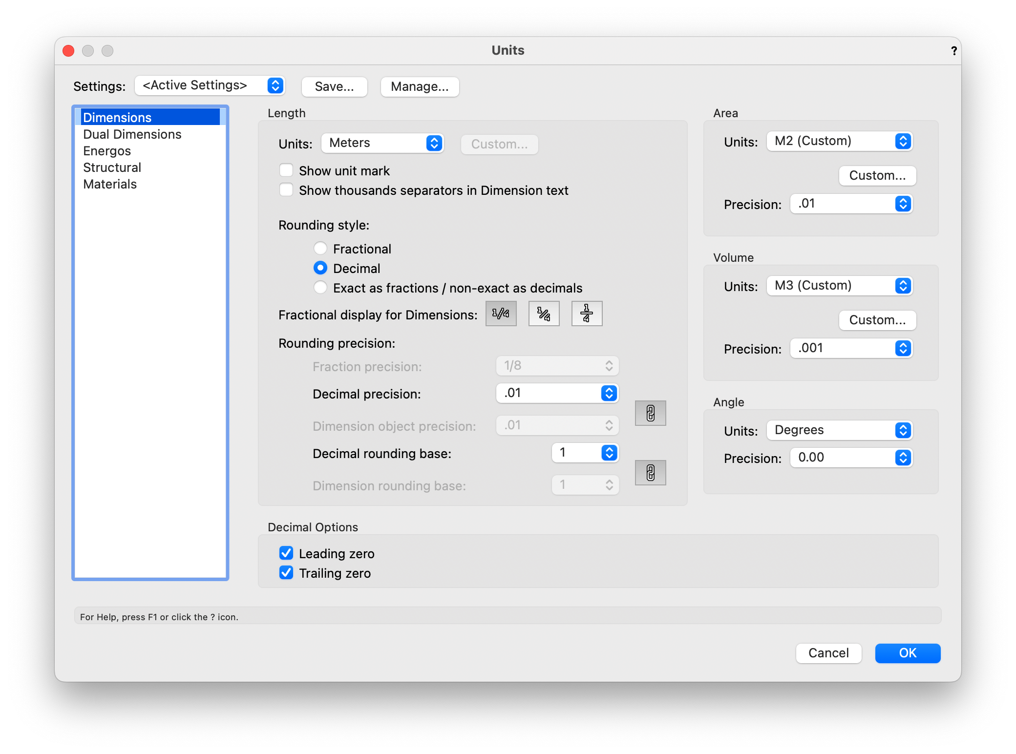
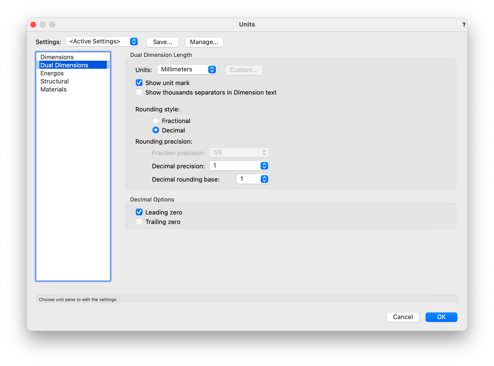
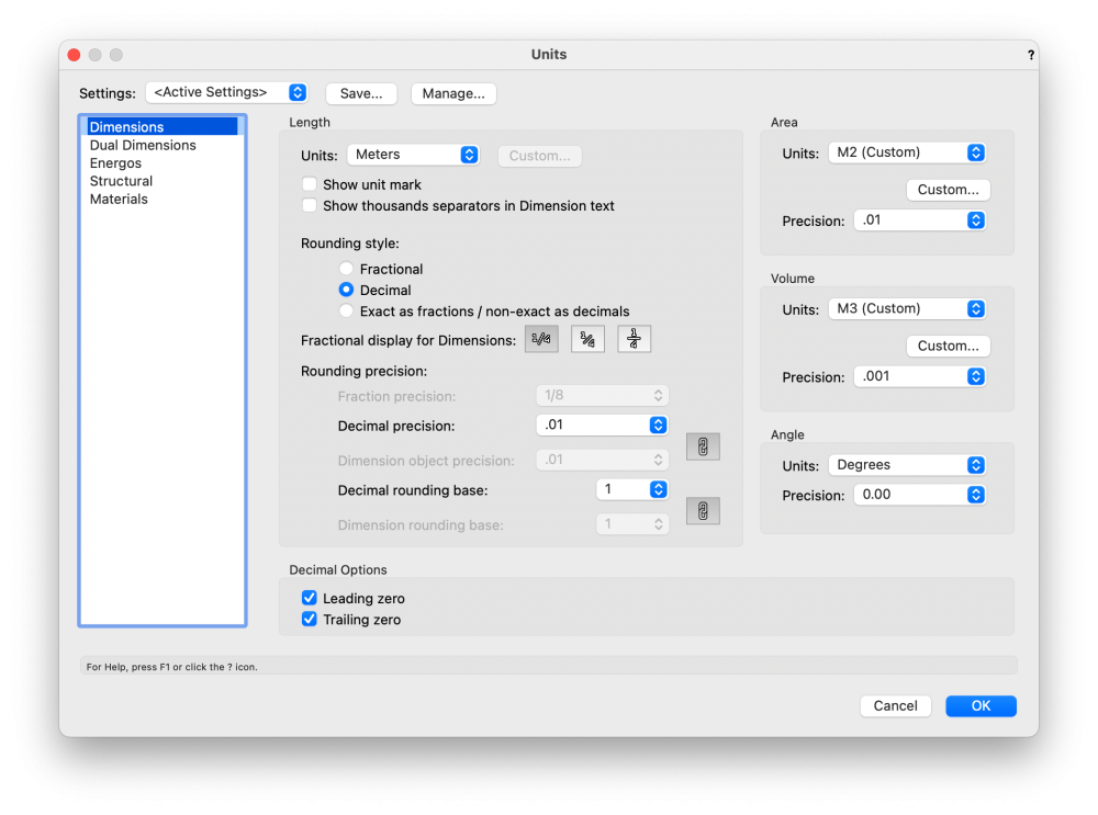
@markdd Beyond wonderful! This'll ease up my life a great deal! Did not realise changing units from document units (meters) to Meters specifically would allow for a second option with precision to be accessed. Exactly what I was hoping for. This solved the shoulder issue as well!
-
Ah, this leads me to another issue I never managed to resolve. Be it because of me or the software. I want to model with a precision of 0.001 m. But I want the majority of my dimensions and stakes to show a precision of 0.01 m. Details are typically shown with a precision of 1 mm. That's just what my standard dictates, can't do anything about that. So I really hope I'm missing something here but it seems that the precision of stakes and dimensions are controlled from the global document Units setting, rather than an individual Dimension/Stake style/setting, which would seem more normal to me. So for this reason I have my units setup as shown below. Not ideal as I'm missing that mm precision in normal modelling, but it's seems the only way for me to show values as needed on my sheets. Please tell me I'm doing something wrong here 🙂

-
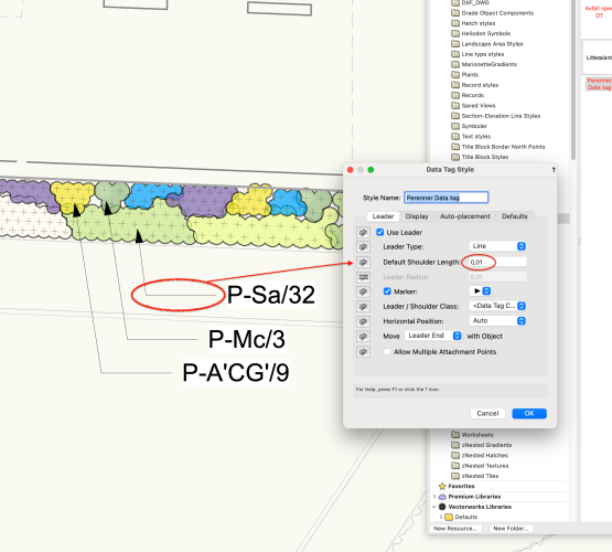
I work with meters as my primary unit. And I want my data tag shoulder lengths to be shorter than the minimal value I can set in the data tag style. Lots of other tools VW allow me to specify a 0.001 precision and even though it ends up showing me a 0.00 value in the properties I actually get 0.001 precision in the model. However, with the shoulder length it rounds of to the nearest 0.01 instead. So if I set the length to 0.004 it rounds to 0 and gives me no shoulder at all. Any ideas of how I can reduce the length of my shoulder below 0.01 meters?
-
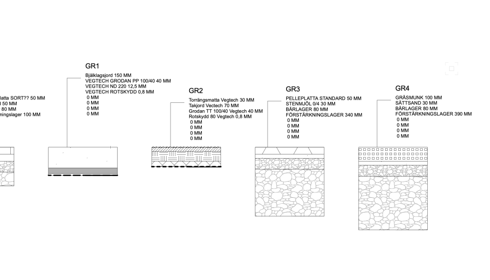
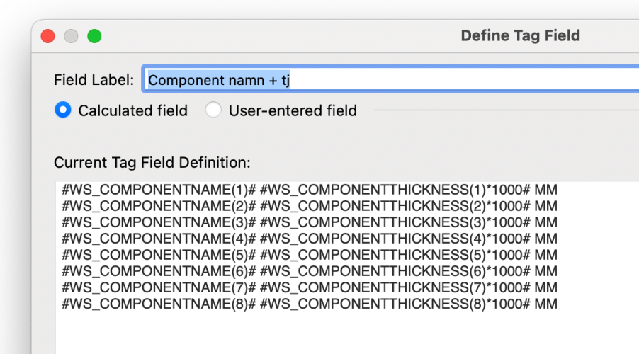
@Zsombor Did you find a way to tag with the thickness and avoid getting extra lines for components that don't exist? When using only COPMONENTNAME it doesn't add that empty line. When adding COMPONENTTHICKNESS I get the 0-lines as shown below.