ebramhall
-
Posts
18 -
Joined
-
Last visited
Content Type
Profiles
Forums
Events
Articles
Marionette
Store
Everything posted by ebramhall
-
Thank you Benson, Both ideas sound like good ones. I'll give them a try asap and circle back with a progress report. Thanks so much, Your help is truly appreciated. Happy fourth! -Everett
-
Hi Benson, thanks for your reply. With regards to a new texture, the designer I am working with would truly like me to make this pattern work, so I have to find a way to convert to solid. Do you know anyone with solid works or ZBrush or Mesh Mixer that I could hire/work with to try converting my files with? VW Tech said they've seen it done and I just need to find someone to send the files to who can run them through a conversion process. Do you know of anyone that you could recommend? -Everett
-
Solid modeling / Shelled Object / 3D printing issues
ebramhall replied to ebramhall's topic in General Discussion
Converting the object to a generic solid unfortunately did not work. I tried it at several different layers and most attempts failed. My next step is to find another software program to export to which can convert the item to a solid. If anyone out there has Solid works, ZBrush or Mesh Mixer, all of these have been suggested by the 3D printing folks. I just need a connection to someone that has the software if possible. Thanks for any suggestions -Everett -
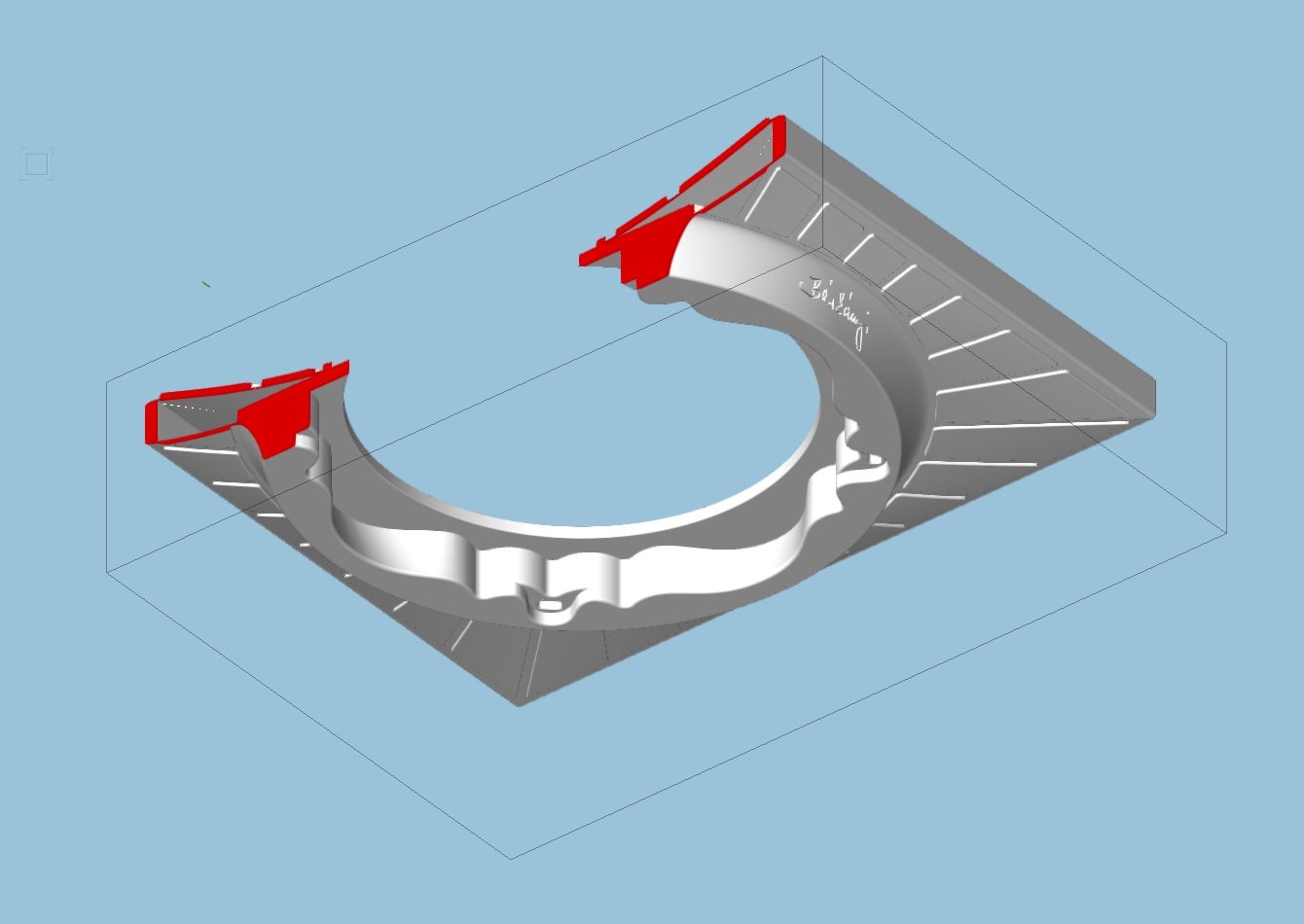
The solid modeling objects I've created in Vectorworks cannot be printed in 3D. Form Labs and other 3D printing companies say the files created in VW appear to be a shell only without a solid interior. I sent an OBJ and an STL file to Form Labs and they said the models need to be converted in another program in order to be 3D printed. VW Tech says they are sure the files can be converted in other software programs that will "fill" the objects and allow them to be 3D printed. They've seen it done, but they are not able to tell me which program to export the files to. Can anyone in the forum recommend a program or service that can convert files for me? Thank you -Everett In the first picture you will see the VW screen shot of the solid modeling object created in VW. In this screen shot you will see the same object with the clip cube enabled. Basically showing a hollow or shelled object. in this picture you will see the conversion software picture generated by Form Labs. They say the walls are not thick enough to print. More they are only a representation of walls or a shelled surface. VW Tech says the files can be converted in other software programs that will "fill" the objects and allow them to be 3D printed. VW is not able to tell me which program to export to. Can anyone in the forum recommend a program or service that can convert the files for me? Thank you -Everett

-
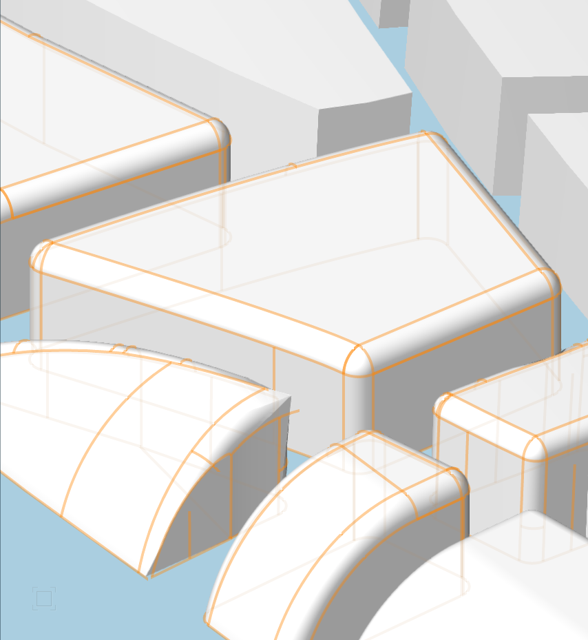
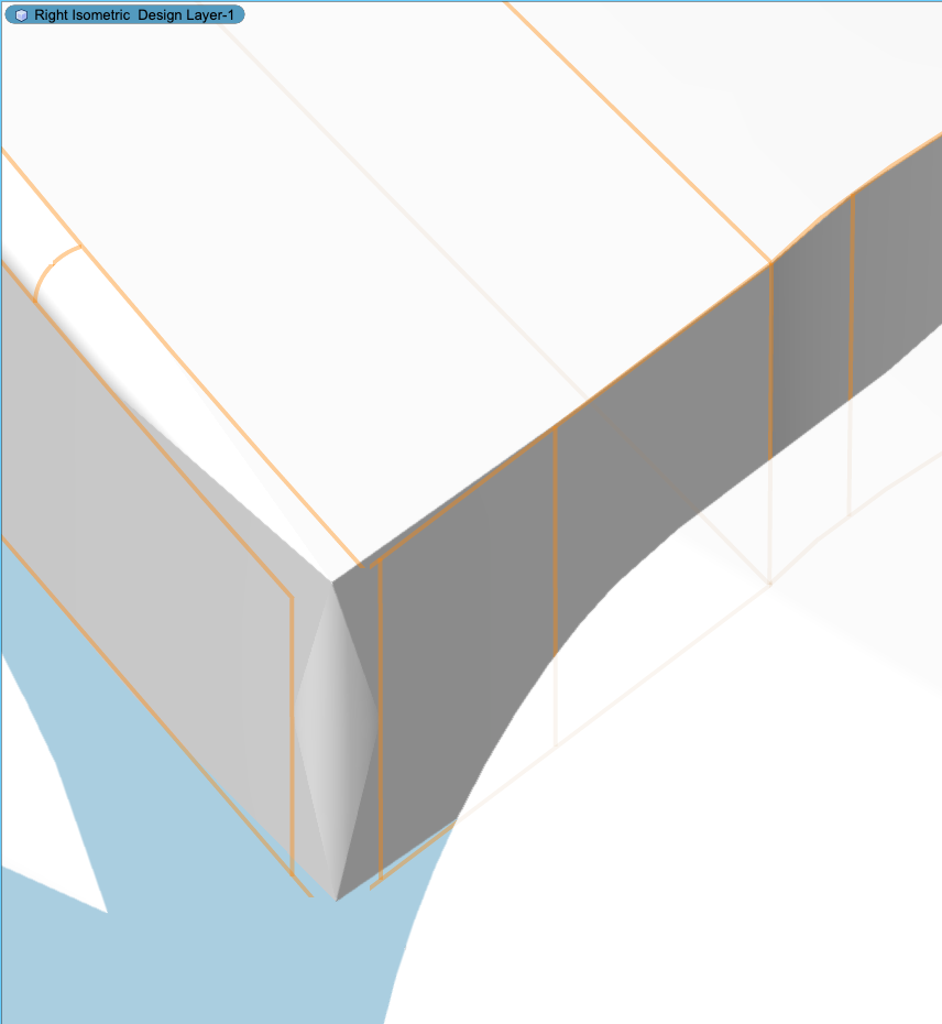
Hi Benson, I put this product on the back burner for a few weeks but just got back to it and was successful per your help and suggestion. Below you will see a a series of pics showing the "flakes" that have been extruded, then subtracted from a curved solid, then extracted and shelled to make a 1.5mm texture square in section to the curve of the initial form. It looks almost perfect (thank you for your help) with one last exception. When I try to put a .2mm fillet on the top surface of the shelled flakes (about the same as the tiny radius on the top surface of computer keys) I discover a lot of inconsistencies and "failed fillet" pop up warnings. You will see in a few of the pics that the corners of the shells are not connected and when I go deep into the history of each flake I only find relatively clean poly lines and closed polygons. When I try using the surface fillet tool I usually get a "fail" and when I use the edge fillet tool (Incredibly cumbersome) It's hit or mis on each edge and corner of each flake. Needless to say the amount of time spent doing this is super inefficient. Would you have any suggestions that might allow me to "clean up" each or all of the flakes and "soften" the top edges? Your help has been extremely appreciated as I am achieving some pretty complex things (for me). Thank you for having a look and I hope to hear back. -Everett PS, Is this type of solid modeling in VW a bit much? Should I be using a different program? Or could I export these models to a different program and get quicker results or more appropriate tools?


-
Hi Benson, Thank you very much, I understand the gist of your suggestion and will give it a go. Basically it sounds like I will be building the texture one piece at a time. It's not really a mapping or a distorting procedure from what you are suggesting. I'll try it out and send you back a few pics. Thank so much -Everett
-
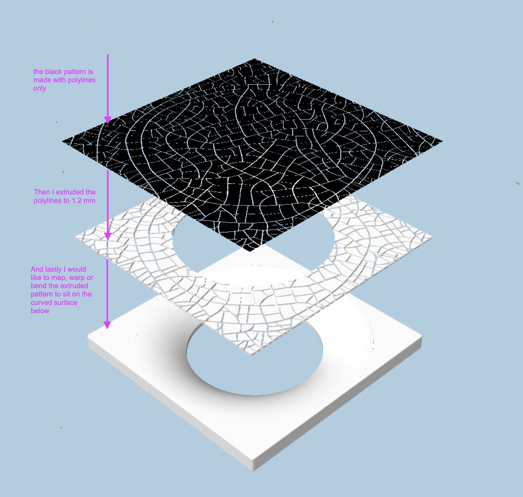
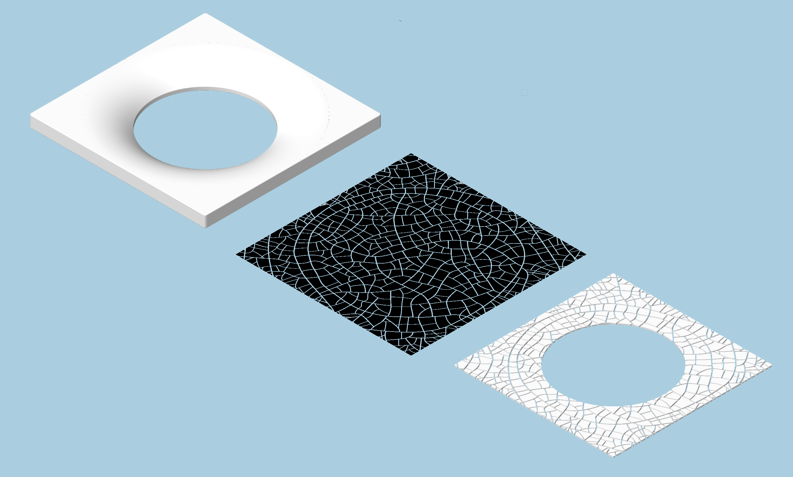
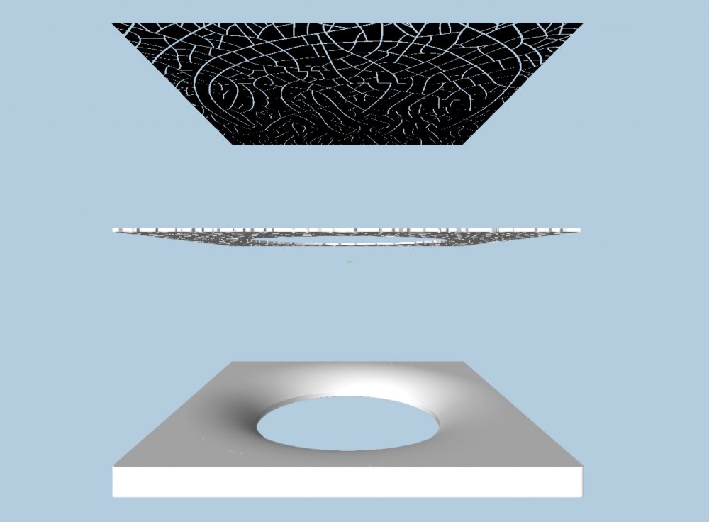
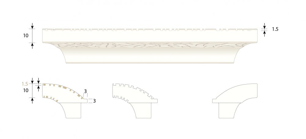
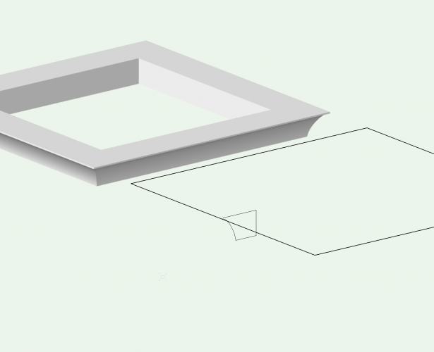
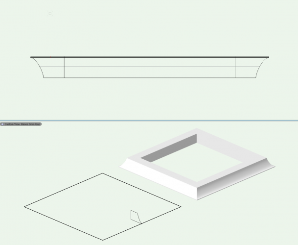
Hi Benson, Thank you very much, I understand the gist of your suggestion and will give it a go. Basically it sounds like I will be building the texture one piece at a time. It's not really a mapping or a distorting procedure from what you are suggesting. I'll try it out and send you back a few pics. Thank so much -Everett Hi Benson, Thank you for your reply. I've uploaded 2 exploded views and a rendering which I hope will explain the process I am trying to follow. 1. I've extruded a texture from a poly line drawing (see top black square in drawing) 2. I would like to have the extruded (mid section in drawing which are the same poly lines extruded to 1.2mm) texture follow the curve of the extrude along path object at the bottom of the stack. I do not want to extrude the pattern and then subtract it from a solid as the "cracks" would then be perpendicular to the ground plane. Rather, I would like to deform the texture so the "cracks" are 90 degrees to the curved surface.The idea is to simulate cracked paint on a curved surface. Does this make sense? -Thanks so much for your help. -Everett
-
Hi Benson, Thank you for your reply. I've uploaded 2 exploded views and a rendering which I hope will explain the process I am trying to follow. 1. I've extruded a texture from a poly line drawing (see top black square in drawing) 2. I would like to have the extruded (mid section in drawing which are the same poly lines extruded to 1.2mm) texture follow the curve of the extrude along path object at the bottom of the stack. I do not want to extrude the pattern and then subtract it from a solid as the "cracks" would then be perpendicular to the ground plane. Rather, I would like to deform the texture so the "cracks" are 90 degrees to the curved surface.The idea is to simulate cracked paint on a curved surface. Does this make sense? -Thanks so much for your help. -Everett

-
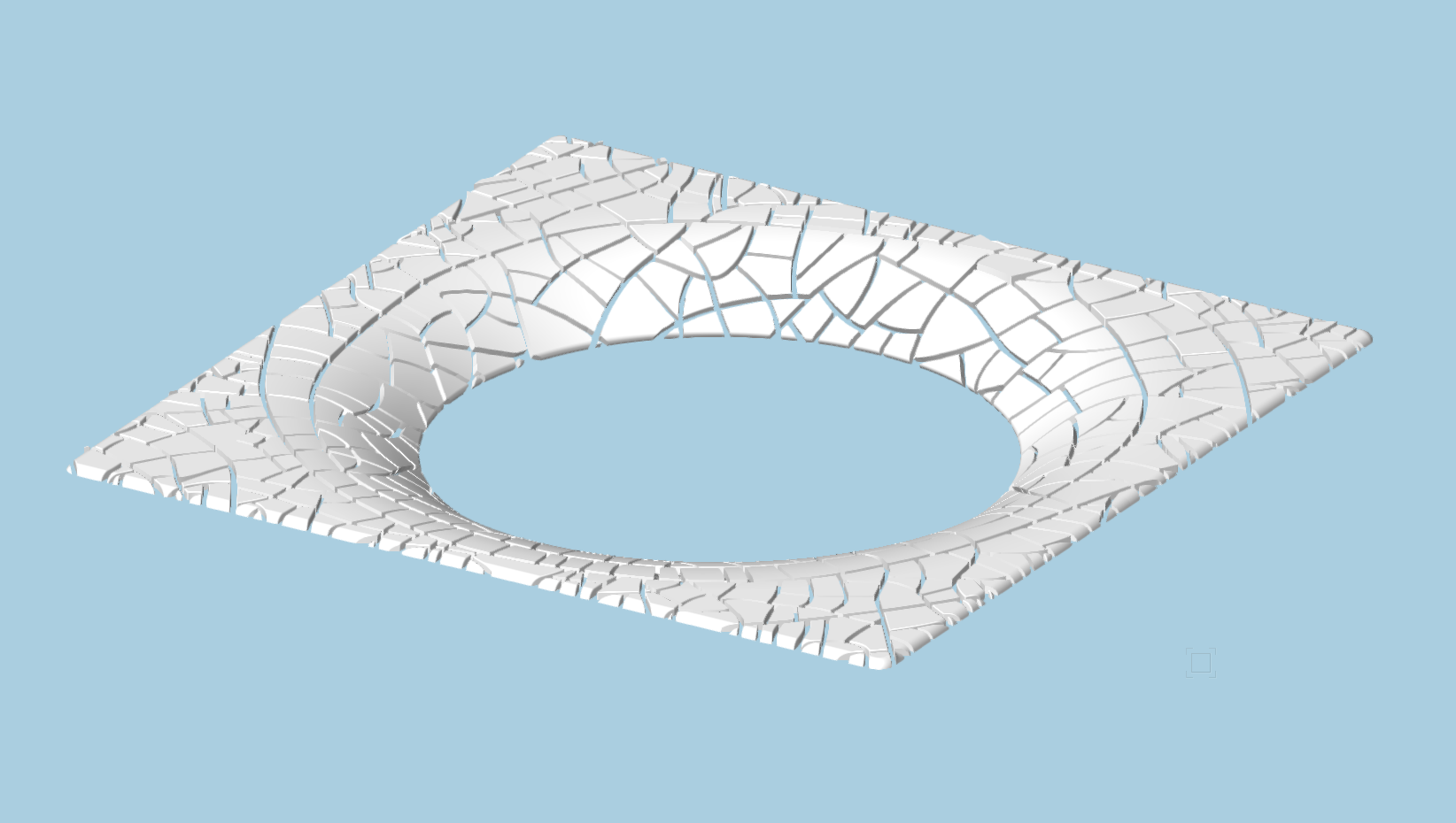
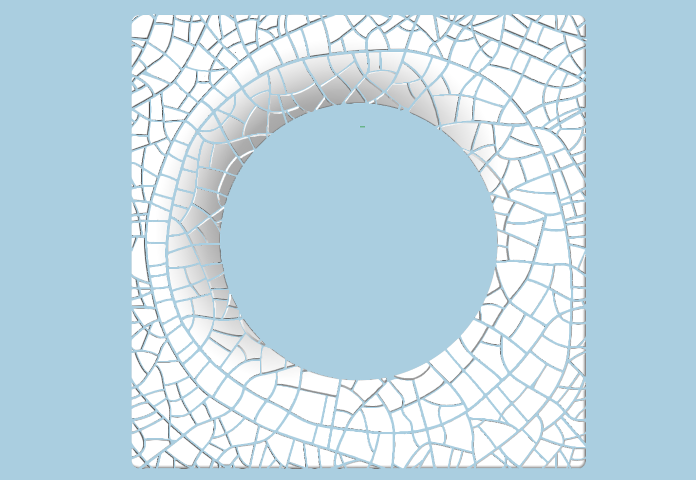
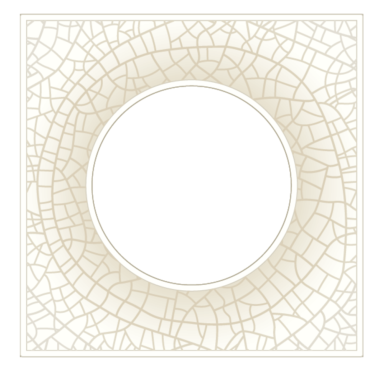
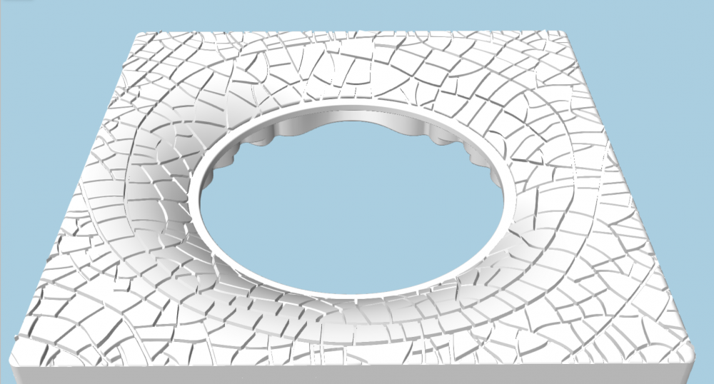
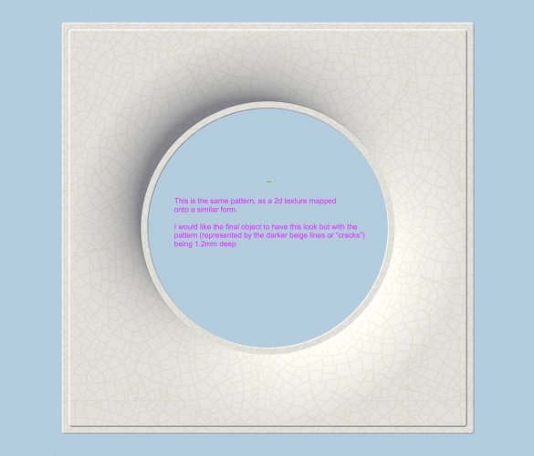
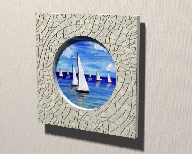
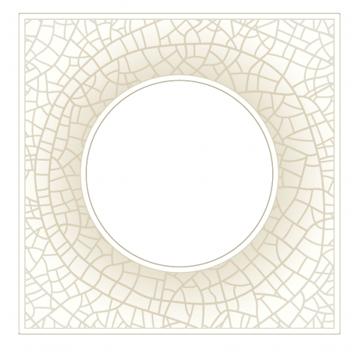
I built a 3D texture on a flat plane (see image Crackle-2) and would like to map it onto a curved surface (see white form in image Crackle-3). Image Crackle-4 shows desired result as rendered in Illustrator. Any help would be much appreciated. Thank you -Everett

-
Thanks Ben, I have been saving versions along the way just in case. Seems I could organize them on Design layers in the exact same location. Good idea. Or classes used the same way... I'll get at it and let you know how it goes. Thanks again -Everett
-
Hi Ben, Your second idea was right on! I was able to build the item following your very detailed and helpful instructions. Thank you so much! Check it out in the picks below. Now I have to repeat the process over dozens of additional items. Hopefully they will all cooperate. Thanks again Ben and Kevin -Everett PS: one last question. When I subtract the solid interior volume with all the curves, (I built that as a positive volume to subtract from the outer shape that you've helped me with) I then radius the wavy edges of that interior surface and the object turns into a grouped Fillet. When I try to edit it, I have to ungroup it at which point the wavy radius disappears.... any thought on that one?
-
Hi Ben, Thanks for sticking with me. I do not know what a cutting volume is.... When you say "Let the cutter round over the entire miter, including those outside pointy corners" can you give me a little more info like where I find that tool? Thank you very much! Everett
-
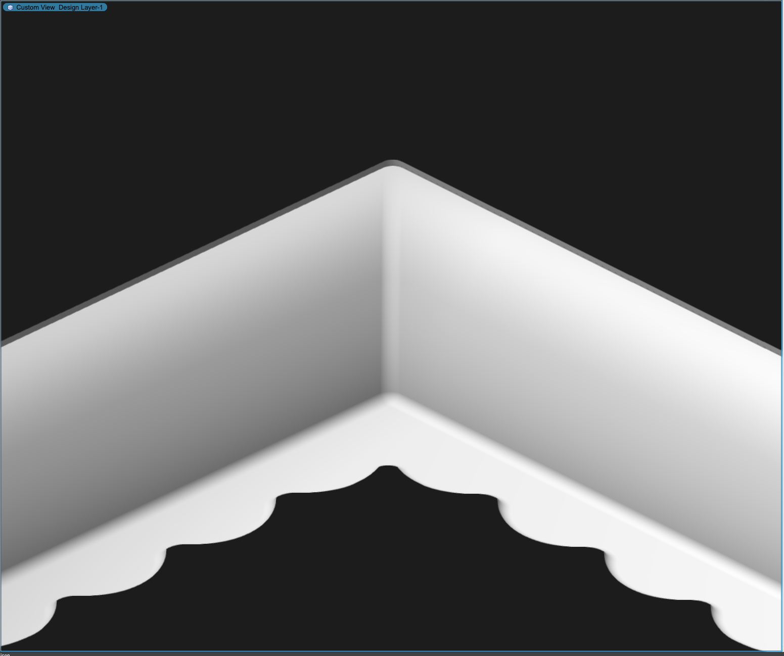
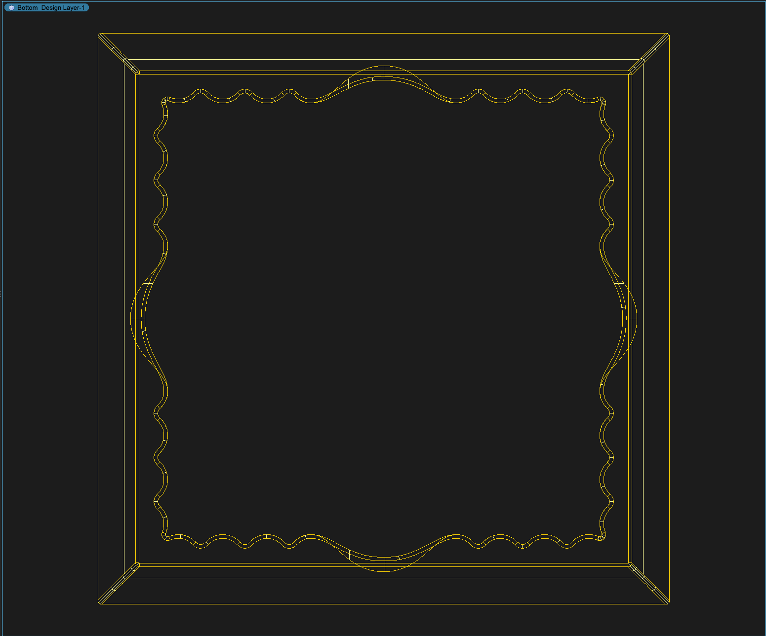
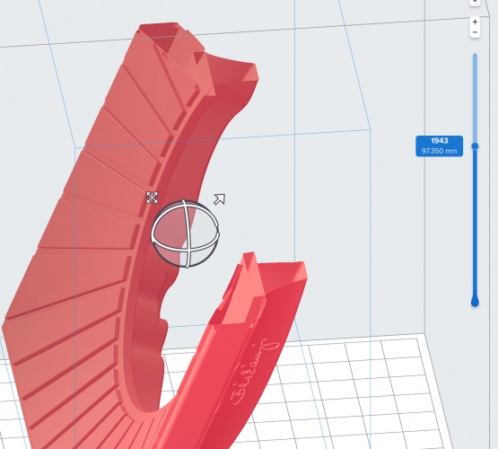
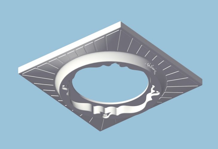
Hi Ben and Kevin, Everything you told me to do worked really well until I tried to put a 2m radius on the bottom edge. (see screen shots attached) When I do this, the extracted edges do not connect and I can't fill in that little gap you can see just above the Corner Extrude. Even when I extrude it higher that section gets full of lines and the Nurbs don't touch each other and won't create a surface for me.... Any suggestions? I attached the VW file as well as a few screen shots if you want to have a look. I would be super appreciative of a tiny bit more advice. Thank you very much! -Everett Corner Raudius Trial.vwx
-
What a great help. Thank you both for putting your heads into this conundrum. I had almost given up. Now that I have very detailed instructions I will attempt to execute in my own files and let you know how it goes. Thank you sincerely -Everett
-
Hi Kevin, Thanks so much for giving it a close look. I discovered the same as you with the filet tool. I even built the same "noodle" as you and tried to add it in.... No luck. Very interesting to learn the Rhino can't do it other... That actually is some consolation! I truly appreciate your advice and may just reach out to Benson if my VW training session doesn't yield any results. Thanks again -Everett
-
I'm trying to do the following.......
-
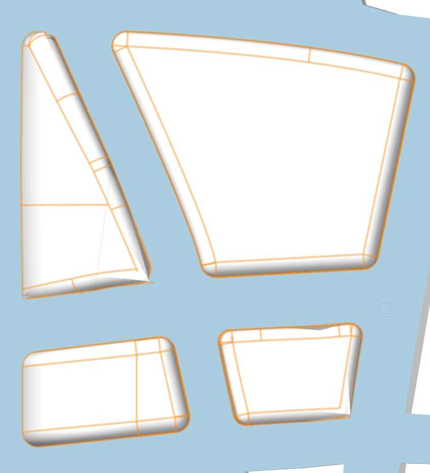
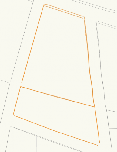
Hi Kevin, The path is a simple square and the profile is a pretty basic poly line.... On the left is the result of the EAP from the rectangle and the poly line on the right.
-
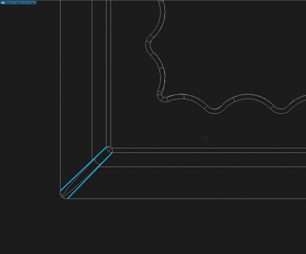
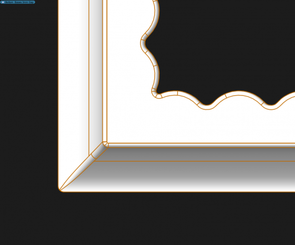
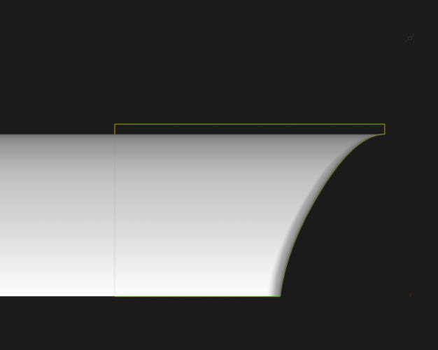
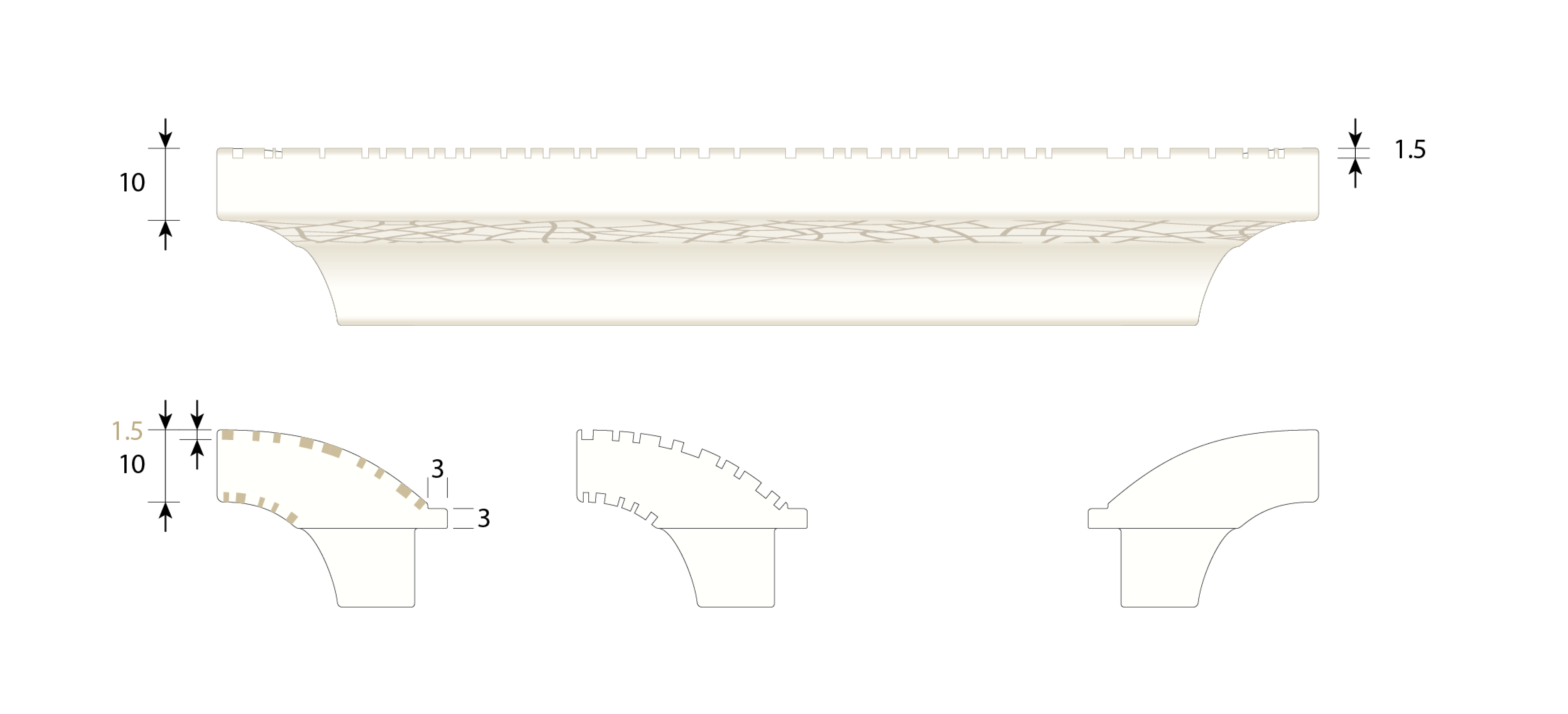
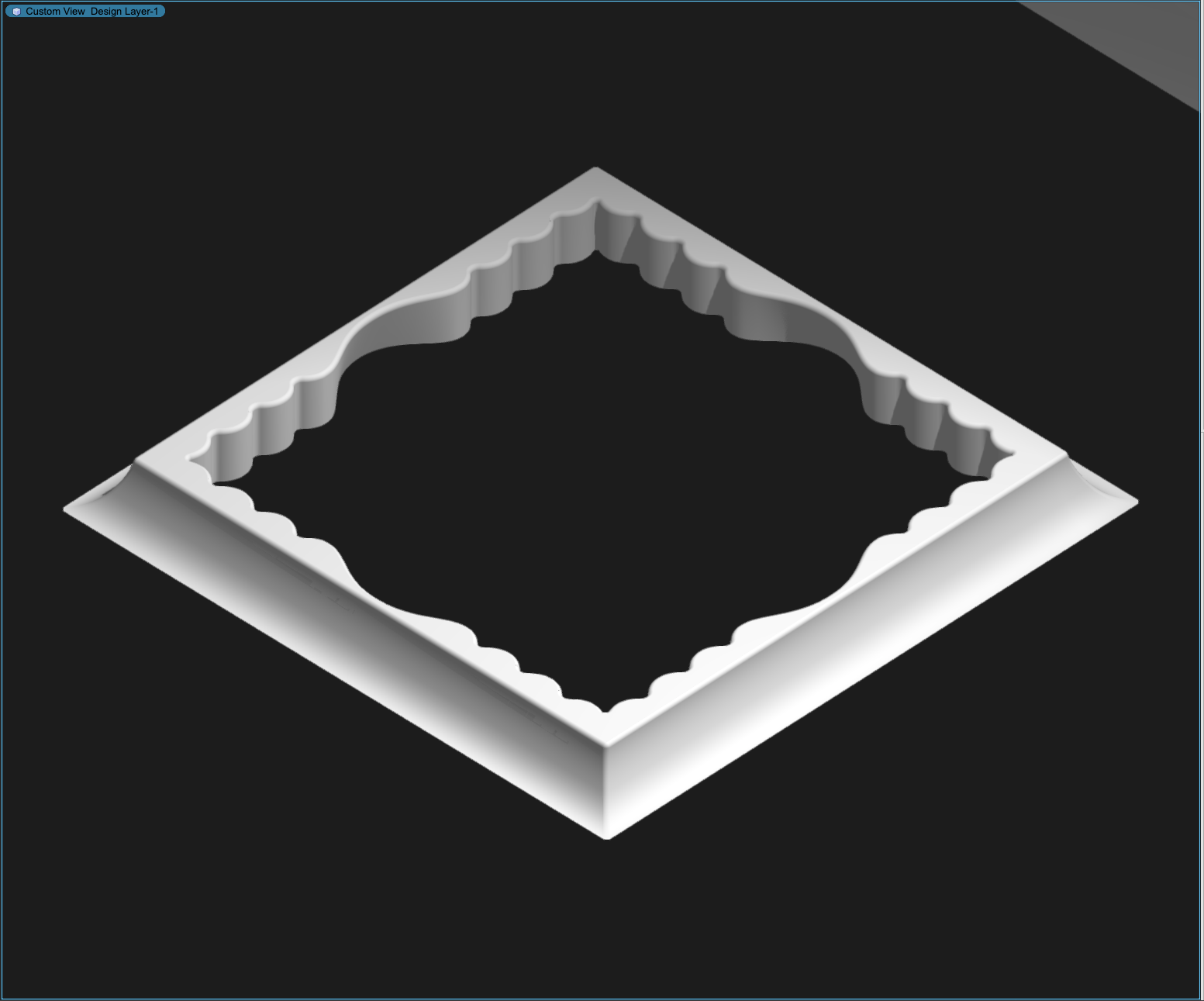
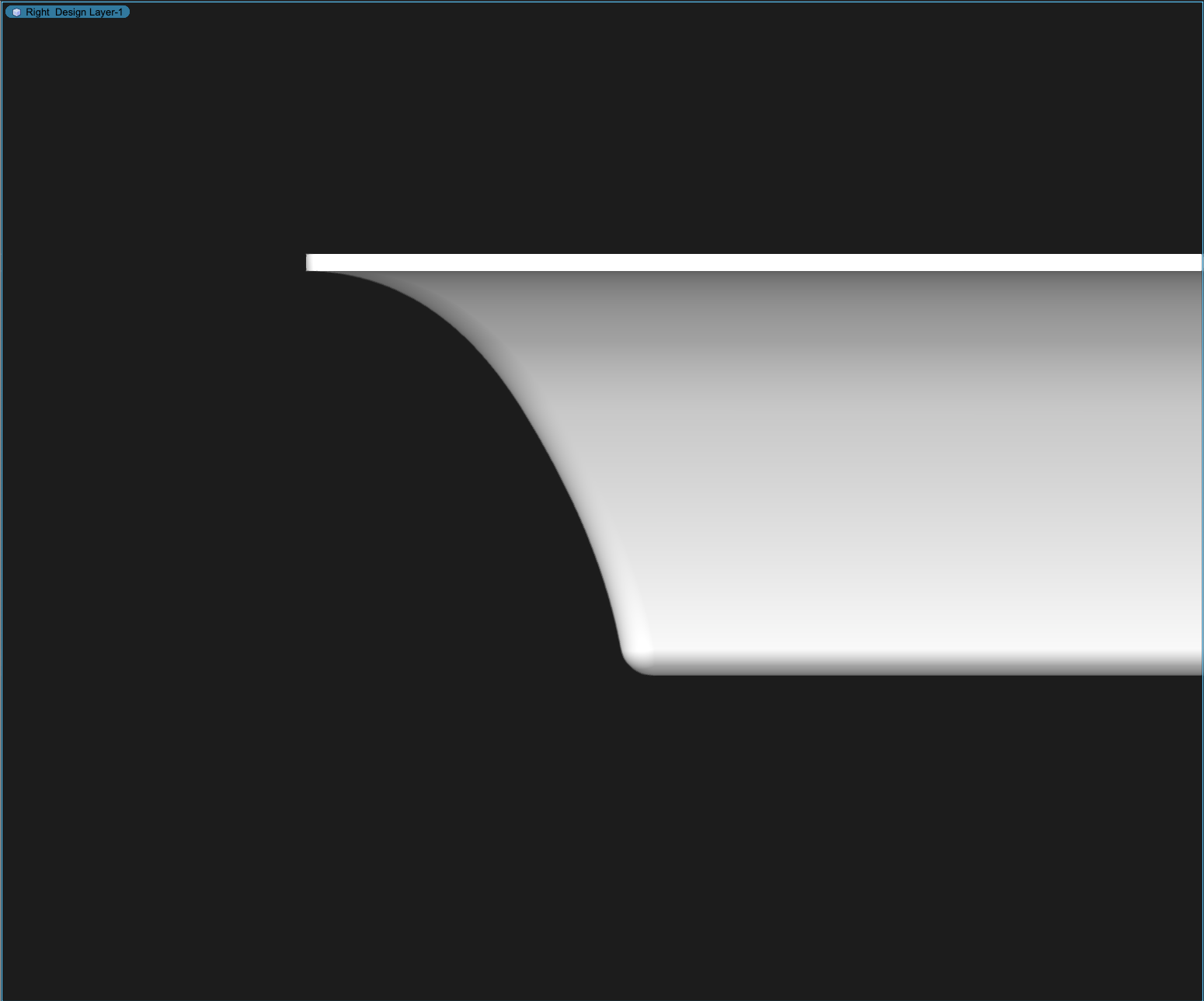
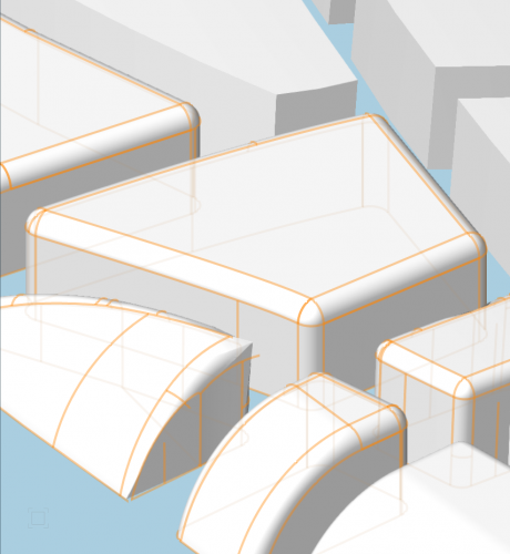
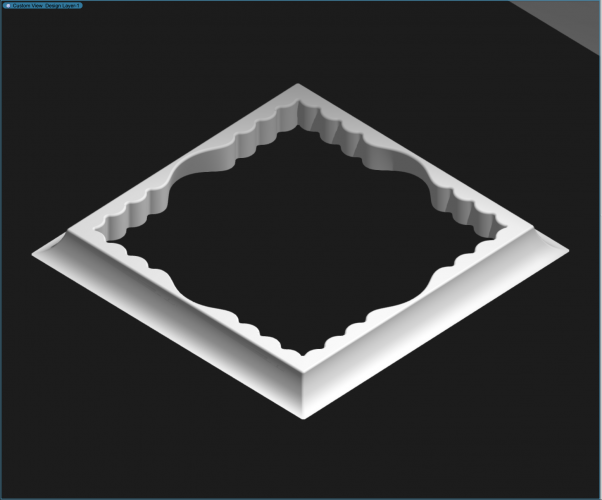
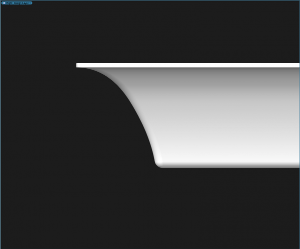
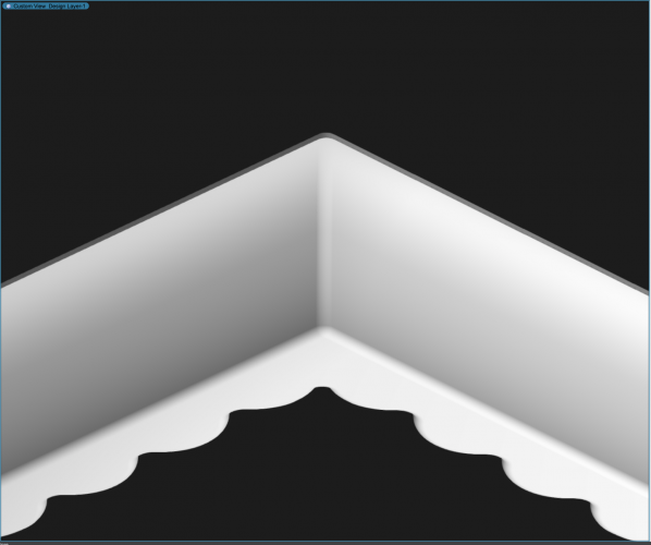
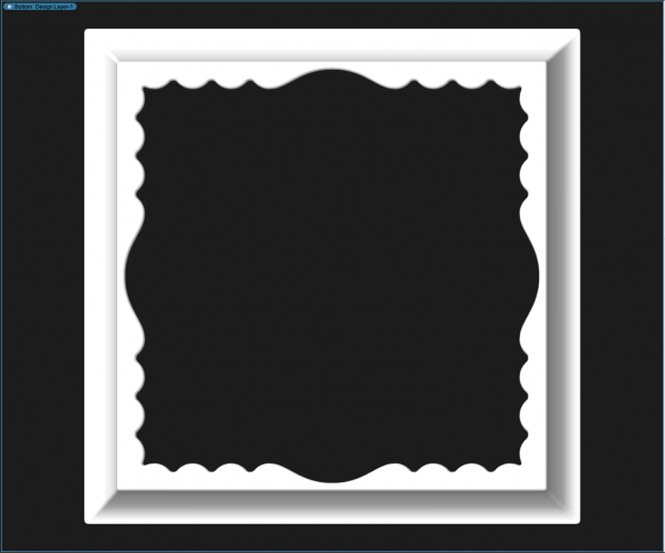
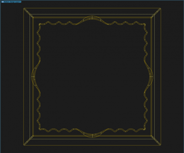
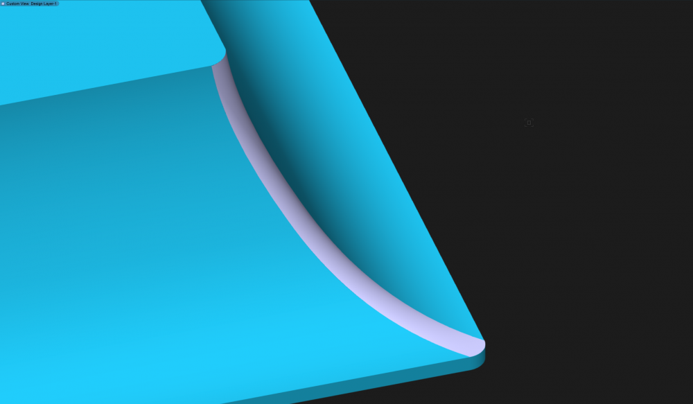
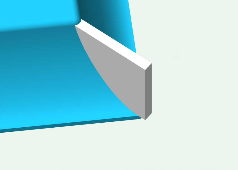
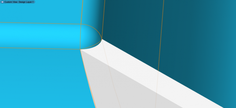
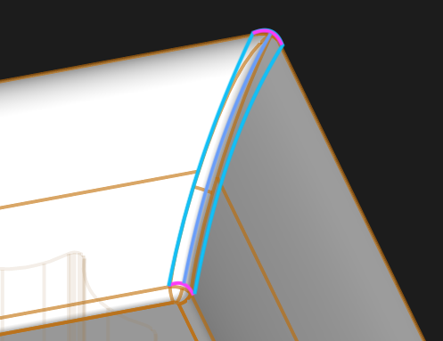
I would like to change the filet on the four curved corners of an extrude along path object. In the first picture the blue lines show how I would like to "open up" the filet. The second shows how the filet tool tapers the radius out to a point, and the third shows the section as it flares to a horizontal line. Because there is no "material" left to radius where it flares out to a point, the filet tool appears to be calculating the geometry correctly so I am thinking the filet tool is not the one to use, or that perhaps an extrude along path object is not correct either. The resulting object needs to be very accurate (for tooling purposes) with regards to the section and top/bottom dims as well. Could I build the same object as a subdivision and then adjust the corner filet per the blue lines in picture One? Or is there another tool / way to adjust the corner radius as desired? Any help would be appreciated. Thank you -Everett