MGilc
-
Posts
66 -
Joined
-
Last visited
Content Type
Profiles
Forums
Events
Articles
Marionette
Store
Everything posted by MGilc
-
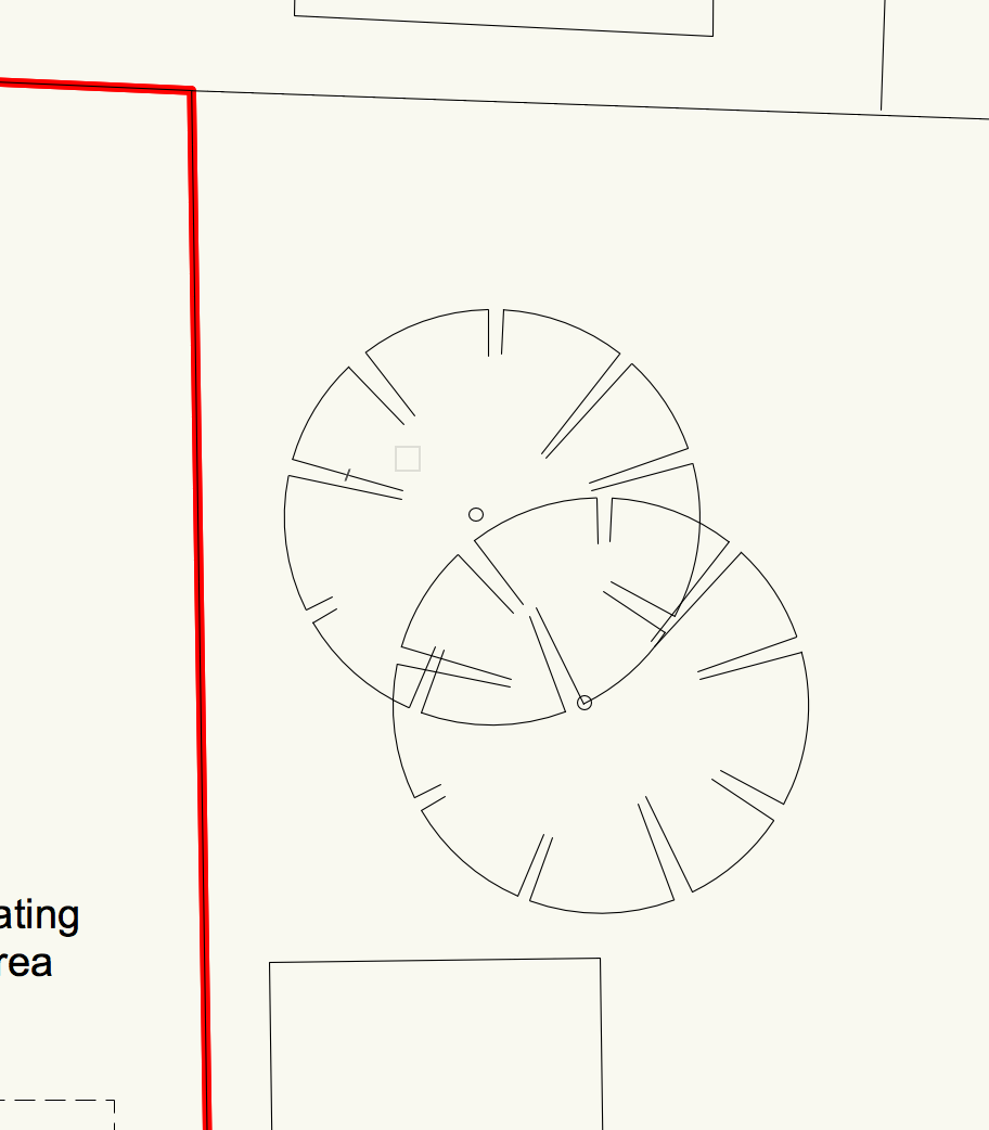
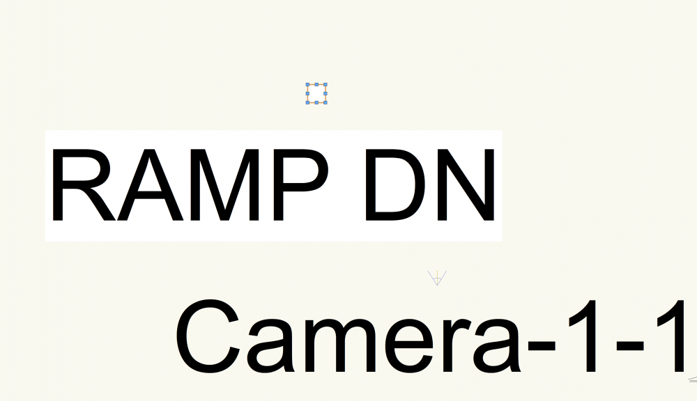
Hi again all, Why when I create a camera or ramp is the text so horrendously huge? I cannot see any option to reduce the text size. Scale does affect it, but why would I have to change the scale of the drawing to accommodate some small piece of text information. That is not a solution. What am I missing here?? On another drawing I was working on, it was normal - the size relative to the camera or ramp. Just for a sense of scale this is at 1:100, and the square in the screenshot is 10 x 10m Thank you.
-
How about for annotations such as for planning drawings to say "new door" or "Remove existing sanitary ware". I just keep that on a different layer and in model space. Similarly for demolition, so far I remove the wall in 3d and draw 2d hatch and dashed line though I expect to not do this when I grasp the proper BIM method.
-
Actually, no problem it was the scale of the document...
-
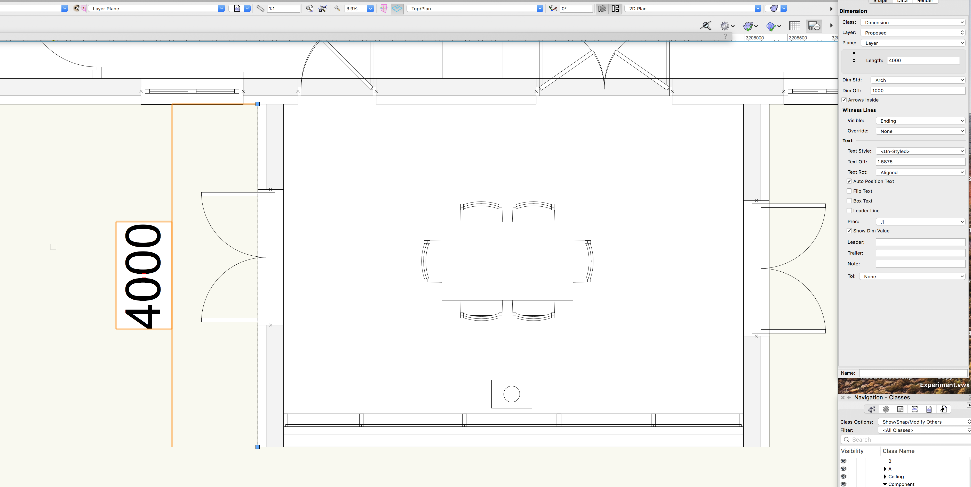
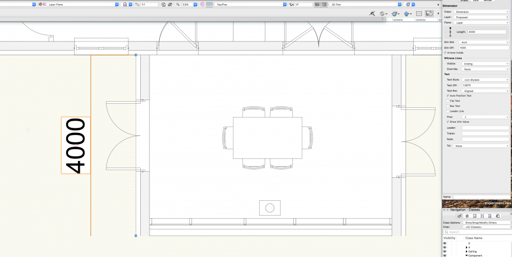
Hi All, How on earth do I change the settings of the dimension tool to show arrows???? It's driving me insane. The Dim Standard in the object info does nothing to change that, and I cannot for the life of me change the text size either. Where am I going wrong here?? Some setting? Brutal. Thanks
-
HI thanks. Got it, yes I used a curtain wall and the same method for a wall. Cheers.
-
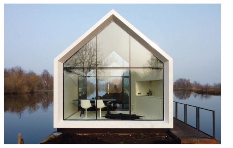
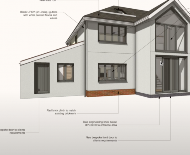
Hi, How would you go about doing a glazed gable like the picture shown? A walled gable can be achieved of course by using the fit walls to object in AEC but how about glazing? Any advice would be really appreciated
-
Ahh I get it thank you!
-
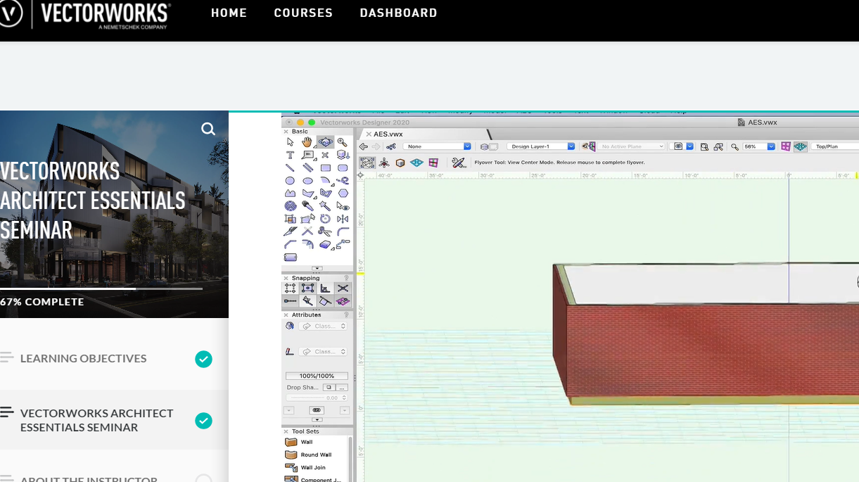
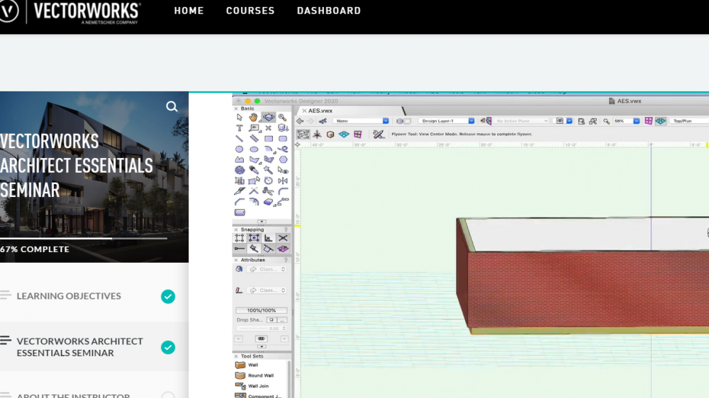
from university tutorial Essentials
-
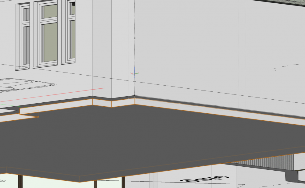
For slabs, should the external walls not start from elevation 0, the slab sit on top of that (so it's surrounded by the external walls) and then all your internal walls will have to have a different elevation (therefore a different layer?) so they all sit on the slab ??? Very confused. What is the correct way to have slabs?? Surely not how the tutorial Essentials suggests.
-
I've a question about the method of creating slabs, as I think I'm doing it wrong. When I create my walls, I use the slab tool which creates the slab and always it sits below the walls (see picture from tutorial from Vectorworks university Essentials). But this isn't how a slab and external wall would be. The walls would go right down to the External ground level, not float above it with an exposed slab; Currently my model has this exposed slab around it (see picture) as the tutorial does it. The walls are on 0 elevation, and the walls built up from the top of the slab, the slab built from top down. I saw a different variation from Jonathon Reeves with the base brick (see picture) How would this be done? Does he essentially draw another base wall around the slab?
-
Hi again all, So I have an existing plan and I just want to show the basic furniture - sink, toilet. I have no intention of modelling a 3D kitchen as it will take time, especially for me. Where in the resource manager are just flat 2d blocks? As always any help would be really appreciated
-
Ahhh ITS TOP PLAN. That's the issue... Sorry fixed now. I will never learn! Thanks!!
-
Ok Thanks for trying anyway. It's the same on a Mac and a pc. Could be just a gappy line type. Kind of infuriating when the model looks one way and the sheet looks another. Reminds me of LT Scale, PSLT Scale, MS Scale...Etc from Autocad.
-
Seems like it's just something on my machine / Vectorworks settings then. What could that be?
-
Actually Is that Paper Space?? Hmm I'm not sure what has happened.
-
@Jeff That looks like model space. If you go to the paper space it's different. My issue is it's fine in model space, but terrible in paper space.
-
Hi, thank you for both your replies. I have attached the model minus the actual design that sits on the slab. It's really kind to have a look at it! The plant was just on Class: None. Sorry what do you mean by using other modes for placing plants? I've so far kept to a 2D site plan just for convenience and time sake. I didn't really want to model in 3d the site plan. Not sure if this is unusual, but I'm working in both 2d and 3d. Copy Experiment.vwx
-
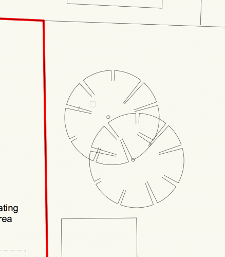
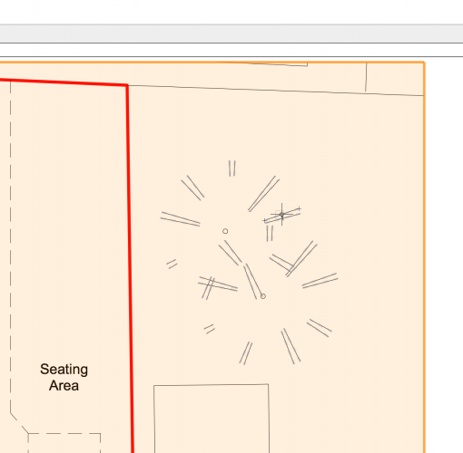
Why are my 2D trees coming in poorly in the viewport? I've attached normal from model space, and the other from the viewport. Also I've heard that you can do hedges in 2d but how do you do this? Thanks again
-
I GOT IT!! I worked it out. Preferences > Display > Uncheck Zoom line thickness (Slow). What a bloody awful button!! Horrendous lol. I've wasted 90mins on this.
-
The normal one below

-
Hi All, Hope you are well. For some reason my line weights have gone chunky thick. I freaked out and for the last hour tried to sort it. The thing is... on another computer, it works totally fine: the lineweights are back to crisp. Therefore I have on my computer / vectorworks settings done something that checked the box "make my lineweights awful". Any ideas which button this is??? Much appreciated! I have attached a picture showing the problem. This is nothing to do with classes or anything

-
Plans - Elements Above Showing Up - How to stop this?
MGilc replied to MGilc's topic in Architecture
Genius. Thanks! It was visible. Fixed -
Plans - Elements Above Showing Up - How to stop this?
MGilc replied to MGilc's topic in Architecture
*"Cut plane in Elevation" (not section cut) in the layers panel -
Hi, What am I doing wrong here with my plans that they show the wall in a doorway? The attached is from the viewport. What are the "x's"? Section cut in the layers panel didn't do anything, is there something in the class of the door that I'm missing? What I would like is a door in a wall. Another matter similar, I made an opening that showed great in plan but then in the viewport the downstand still showed in normal line weight and therefore the opening wasn't clear at all. What was the issue causing this? Thank you as always. Best, Michael

-
Thanks everyone. I think I'll go for extrudes right now. But I'll look at it in more detail again. I really appreciate all of your insights and help!