


Pat Stanford
-
Posts
12,594 -
Joined
-
Last visited
Content Type
Profiles
Forums
Events
Articles
Marionette
Store
Everything posted by Pat Stanford
-
adding or subtracting screw thread often "cannot be computed"
Pat Stanford replied to Funkart's topic in Solids Modeling
I think Virtual Environs is correct that it is intersecting geometry. I think somewhere in the sweep, the "back" corner of the profile polygons are overlapping. I slightly "sloped" the back edges "down" to make the back edge slightly smaller and then the sweep and the shaft were able to be Added. Original Modified Vectorworks really does not like having overlapping geometry in the same object.

-
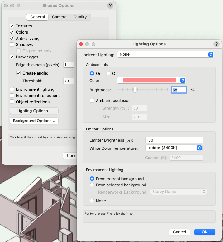
Check your Shaded Options from View:Rendering menu. Make sure you don't have the Abient light color set to pink like I do in the screen shot below. Default is White.
-
Unable to launch Vectorworks Cloud Services
Pat Stanford replied to DianaK's question in Troubleshooting
I just got the same thing and then Cloud services launched. It sounds like a cloud problem on the server end. Try again now or in a couple of hours. If it still exists, contact Technical Support. -
There is definitely something wrong with your file, but I have not been able to identify it. I was hoping one of our other dedicated troubleshooters would have noticed this thread and taken a look. TL:DR - Walls in the same class and same style (single component with solid lines) have different appearances with some walls not showing the wall lines. When the layer is copied and pasted into a different file all of the walls show correctly.
-
Use just Database not DatabaseByScript. Database takes critiera (like your record.field) DatabaseByScript requires a relatively complicated script to specifically identify every object in the database in the correct order.
-
I think you are going to have to post the Vectorworks file for anyone to actually figure out what is wrong. There are too many possible interactions to do more that guess without seeing the file.
-
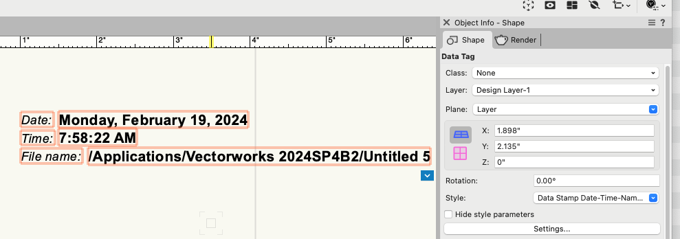
I would start with a Data Stamp formatted Data Tag. The defaults are in the Vectorworks Libraries:Annotations:Data Tag (styles):Dims_Notes:Data Tags.vwx Versions for Long medium and short names. If you don't need the date or time you can edit the Data Tag to remove them.
-
@zoomer ??
-
Did you ever get an answer to this? This is not something I have seen before. There is a setting to assign objects inside groups to the same class as the group and it has an Always Do button. If that was set, then the objects inside the group would end up in the same class as the group. But that does not seem to work with symbols. And it would not explain why you are getting Random classes.
-
I cannot get 'Space'.'Window Area Ratio'
Pat Stanford replied to mattao's topic in General Discussion
Sorry, but I just got back to this. I finally found the Window Area Ratio. It is in the 2D Boundaries and Area section and can be added to the OIP by checking the lines in blue in the Advanced Settings for the space. Here is a simple script that will set the ratio for a Space that is the first selected object in the Active Layer. Procedure SetWindowAreaRatio; Var H1 :Handle; R1 :Real; Begin H1:=FSActLayer; If GetName(GetParametricRecord(H1))='Space' THEN BEGIN R1:=RealDialog('Enter Window Area Ratio for the selected Space object', '0.20'); SetRField(H1,'Space','Window Area Ratio',Num2Str(3,R1)); END ELSE AlrtDialog('First Selected Object Is Not a Space'); End; Run(SetWindowAreaRatio); The decimal and fractional versions appear to be separate and have to be set separately. I don't think a Space has any knowledge of windows in the walls that surround it, so I don't think there is a way for the value to be automatically calculated. HTH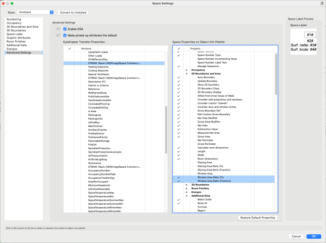
-
adding or subtracting screw thread often "cannot be computed"
Pat Stanford replied to Funkart's topic in Solids Modeling
For us to help you we want you to upload the VWX file so we can see what is happening. Export to STL and then reimport results in an entirely different object. We want to see the original object. -
Opacity of objects changed to 100% when extruded
Pat Stanford replied to JYates's question in Troubleshooting
It looks like the texture of the original object was assigned to the class. See in your first screen shot the the OIP say Texture: By Class for the desktop and None for the circle. What you did is fine, but if you have a bunch of parts that need to be textured the same, you could put them all in the same class, assign a texture with transparency to the class and then tell the objects to use the Class Texture. Glad you got it working. -
Opacity of objects changed to 100% when extruded
Pat Stanford replied to JYates's question in Troubleshooting
Opacity does not apply to 3D objects. It is a 2D only attribute. For 3D objects like the extrude, you need to apply a Texture that has transparency. Check the Render tab of the Object Info Palette (OIP) for the desktop and you should see that it has a texture applied. Apply the same texture to your extruded circle and it should show you transparency. -
Problem with "Use Symbol" for 3D rack equipment items
Pat Stanford replied to SSvectorproblems's topic in ConnectCAD
Symbols with their name in Black are standard symbols. Symbols with their name in Blue have the Symbol Option of Convert to Group checked. That allows the symbol to exist as a resource, but when it is placed in the drawing you will not get a symbol but rather a grouped copy of the objects in the symbol definition. If there is only a single object in the SymDef you will get that object places in the drawing. If there is more than one object in the SymDef you will get a group containing the copy of all the objects. Symbols with their name in Red are kind of a subset of Blue Symbols. Red symbols contain a single Plug-in Object. When you place the symbol in the drawing the PIO is placed instead including all the setting of the PIO before it was converted to a symbol. Red Symbols are also Object Styles. When you save an object style it creates a Red Symbol containing the settings for the object. This can be used either as the default style for a tool or to Replace a style of an object in the drawing. Symbols with their name in Green are like Black symbols, but they are Page Based. This means that that symbol will display at the same size regardless of what scale the layer they are placed on is. This can be useful for objects like drawing labels and north arrows. HTH -
You don't even need a custom record. As long as you can identify the areas you want to calculate for, just us a formula of =Area in one column or even =Area*3 and then multiple that times the column that you have the price in. If you have problems, please post a file with your worksheet (and some sample data). It will be easier to tell you what needs to be changed working on your actual worksheet rather than by guessing and making assumptions on what columns hold what data.
-
Multiple search criteria using & operator
Pat Stanford replied to htranbos's topic in Python Scripting
So like this? "(((T=RECT) & (T=NURBSCURVE)))" Or does that have one to many sets of parens? Or do the individual criteria also need to be quoted separately? -
Multiple search criteria using & operator
Pat Stanford replied to htranbos's topic in Python Scripting
The criteria builder gives: (((T=RECT) & (T=NURBSCURVE))) But Looking at the ForEachObject sample code on the developer site it looks like you may need to use quotes in Python. https://developer.vectorworks.net/index.php?title=VS:ForEachObject ((("T=RECT") & ("T=NURBSCURVE"))) Good luck. Please report back when you figure it out. -
adding or subtracting screw thread often "cannot be computed"
Pat Stanford replied to Funkart's topic in Solids Modeling
Please post the VW file. Did you create the threads in VW? Or in some other program and then imported? -
Multiple search criteria using & operator
Pat Stanford replied to htranbos's topic in Python Scripting
I think your criteria are wrong. I am a Vectorscript guy not Python, but I think you need parentheses and not quotes. Open the VS editor and use the Criteria builder there to generate the criteria you need and then paste it into your script. I always fight to get the parentheses correct, but from memory I think you need: vs.ForEachObject(sel, ((T=RECT) & (T=NURBSCURVE))) -
Or use a general search engine (ie. Google) and add an extra search term of "Site:Forum.Vectorworks.Net" (without the quotes. This extra term will force the search engine to only return hits from the Forum web site.
-
Someone with more Site Model experience than me should probably chime in, but one thing you need to know is that Site Models don't support undercut areas. So if your basement has a larger footprint than your building you won't be able to run the site model up the the building foundation.
-
There does not seem to be a roundup function using the Data Tag formatting. But you can convert it to use #WS_ # functions instead and use Roundup there. Untested, but something like: #WS_Roundup((Screens.Load*Screens.Tubes*20)*3/512,2)# This should round to 2 decimal places. Change the last 2 to however many decimals you want.
-
I haven't figured out how to use a unistrut profile with the Structural Member tool yet, but here is a 2D profile symbol that will work with the Framing Member tool. This is the standard 1 5/8" x 1 5/8" size. I don't think you can force it to have the slotted back. Unistrut.vwx
-
I opened your file and was able to Export your title block to a different file without a problem. Select the TB in the Resource Manager and right click on it. Choose EXPORT from the popup menu. Choose the file you want to store the TB in. Ask again if you are still not getting it.
-
I was thinking about something like this. Sorry if my Python is not very good. Change the accuracy to determine how close to the same angle you want. accuracy = 0.0001 if ((ObjAngle < Rotation + accuracy) and (ObjAngle > Rotation - accuracy)) or ((ObjAngle < RotationReverse + accuracy) and (ObjAngle > RotationReverse - accuracy)):

