Matthias Sch.
-
Posts
27 -
Joined
-
Last visited
Content Type
Profiles
Forums
Events
Articles
Marionette
Store
Everything posted by Matthias Sch.
-
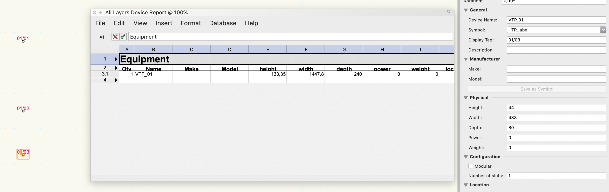
 - Create a device with the device builder tool - Give it a name (for example: USB Hub) - Duplicate the device - Open ConnectCAD > Documentation > * Device Report Then you see one line (because it's the same device). But the QTY field stays at "1" but instead the fields height/width/depth/power/weight are summed up. See attached screenshot. (There you see an example with a Term Panel, but it's the same behaviour with all devices). I found a workaround for my use case. But still i think it's confusing in a default template to sum up dimensions? 🙂 If somebody needs the workaround: - ConnectCAD > Documentation > All Layers Device Report - View > Database Headers = ON - Row 3: Right Click > Summarize Items = OFF for all columns except Name, Make and Model - Row 3: Right Click > Sum Values = OFF for all columns except Qty
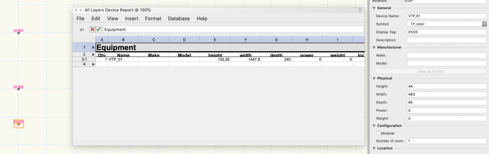
-
As a workaround you can just empty the default SignalTypes.txt file. The one from the application folder, not the user folder.
-
Yep - the new Term Panel Tool is awesome 🙂 Just tried it - Thanks!
-
2021: Device Builder takes long to show
Matthias Sch. replied to Matthias Sch.'s topic in ConnectCAD
Hello @Nikolay Zhelyazkov, Yes - It does this always, not only the first time. Okay. Tested again: The initial one takes about 4-5s, and the others about 3-4. And also when switching from Category "User-Defined" to "<All>". If there is a cache after the first run, and I assume you do not reload the whole file when a category is changed, maybe it's the propagation of the "Make/Model" list? Best regards Matthias -
2020 > 2021: Already Connected Term Panels Broken
Matthias Sch. replied to Matthias Sch.'s topic in ConnectCAD
Wow - that was fast! Thank you! -
2020 > 2021: Already Connected Term Panels Broken
Matthias Sch. replied to Matthias Sch.'s topic in ConnectCAD
Hi Conrad, thanks for the hint. Is this new in 2021? Best regards Matthias -
I really like the fact, that changes to "Devices DB" do not require a restart of VW any more 🙂 Thanks for that! But now, it seems the Device Builder loads the file every time it is displayed. I measured it a few times, and it always took about 3.5 to 4.5 seconds from clicking with the tool until the window is shown. Since this is every time I used the tool, it get's a bit protracted when inserting lots of devices with this tool. It looks like it loads and parses the list every time the window is shown. Maybe some kind of cache would be cool (based on file change timestamp)? Or a button to reload the files in ConnectCAD setting (like for connectors and signal types)? No Test-File needed. Steps to reproduce: - Open a new document based on ConnectCAD Metric template - Select "Device Builder" tool - Click at the document ... you see the delay then. Tested on: Latest MacBook Pro 16", macOS 10.15.6, 8x 2.4G i9, 64GB RAM, VW2021 INTL.
-
After Upgrading from 2020 to 2021, already connected Term Panels can not be connected with a 2nd wire. Example: You have 2 Term Panels for connections between 2 locations, and then (besides the location link) you want to add the connections for the devices. - This was possible in 2020, but clicking the Socket in 2021 does just ignore it. - Connection an unused socket works. - Changing the "Number of Circuits" to 2 on the inside port object does not help. - Deleting the "location link" allows a new connection. But still only 1 at a time. See attached files. In 2021, it is possible to connect things to TP 17-20 but not to 01-16. TermPanel2020.vwx TermPanel2021.vwx
-
i can confirm this - copying the files manually worked for me
-
Hey Conrad, thanks for this really detailed solution. The workaround with ungrouping and pasting into a new device is god to know as a solution for this one: But now it looks like a bit more effort then I was trying to explain ... I'm sorry. I was really searching for a quick way to just change a few sockets without having to edit every single socket. I know about saving a new symbol, but in this case this is not a solution, since the term panels do not always have the same amount of same connectors. Like having the "Object Info" item from attached screenshot 2 at the level of attached screenshot 1. Bit I think this requires some kind of "link" from the device itself to the inside socket? Currently it it like in attached video. But this can be time-intense for lots of term panels. Best regards Matthias Screen Recording 2020-09-19 at 20.48.15.mov

-
+1 for the multi-connect 🙂
-
Hey Conrad, thanks for that. But I wanted to change the "Connector" field on multiple/all items. For example from RJ45 to RJ11. Unfortunately I have to wait until November for 2021. Even if I'm using the EN version, but it looks like I can't get a 2021 serial before 2021 DE version is released (i bought the german version but the whole team uses english) 😞 By the way: I normally use search app-help.vectorworks.net before asking 😉 Best Regards Matthias
-
Signal Type lost after reshaping connections
Matthias Sch. replied to Matthias Sch.'s topic in ConnectCAD
Wow - That was fast 🙂 Thank you! -
Hey, I was searching for the same thing. I think at least 3 settings would be really helpful: - vertical spacing (from line to line) - horizontal spacing (from line start point to line start point) - vertical items (if set to 5, then after 5 items it jumps to the next column with $horizontalspacing distance 🙂 ) - and an option to hide the default "legend" label Just as an idea. It would be really helpful because I think most legend "formats" can be done with this, and it does not break the "refresh" function (as the vwx group does). Best Regards Matthias
-
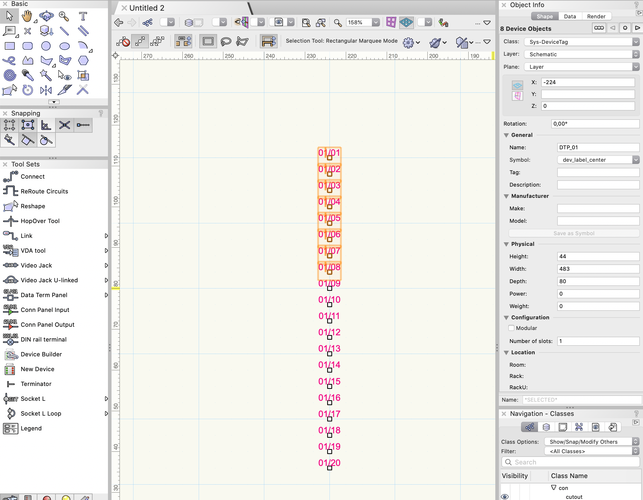
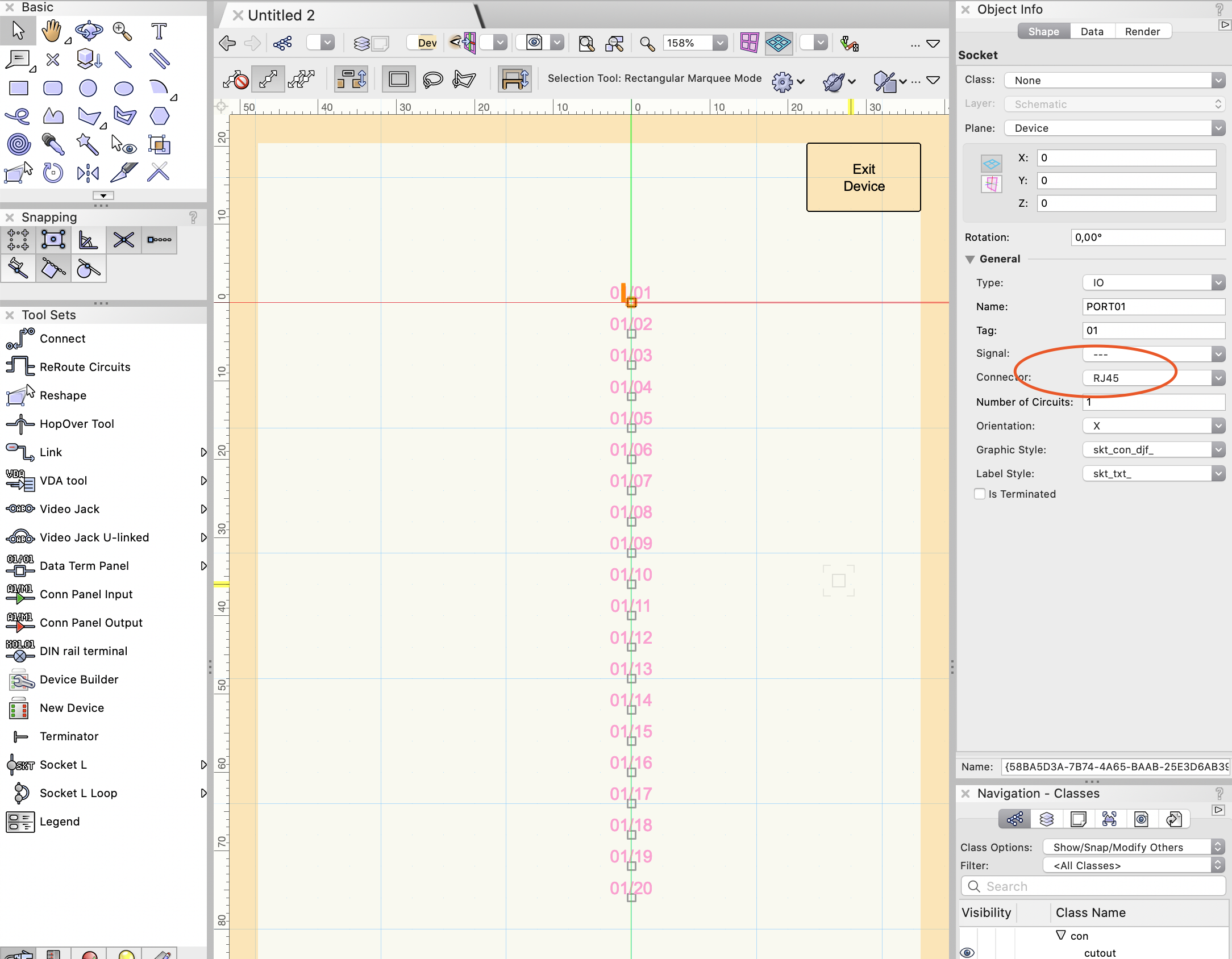
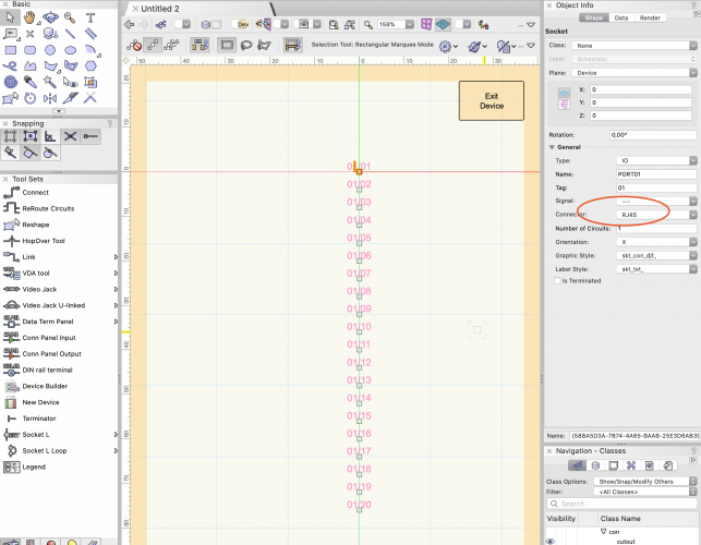
Hi there, another *TP (term panel) question incoming. I know, it looks like I#m practicing for the next patch-panel-olympics 😉 Is it somehow possible to change multiple/all connectors at once? Imagine you have a RJ45 data term panel with 20 connections, but need RJ11. Currently the only way is: - double klick on DTP socket device - click on the socket - select the connector from dropdown list - exit device ... and repeat this 20 times. I'm wondering if there is a "mass edit device" tool or something like that? I gave the Spotlight Numbering tool a try, but this only sees the whole device and not the underlaying socket object. Thanks for any hint 🙂 Test-File is attached ... Best Regards Matthias Test-ChangeSockets.vwx
-
Regarding the workaround: I tried to avoid the direct connection, because the other socket is literally at the opposite side of the whole drawing 😄 An idea for a more permanent solution - just thinking out loud: Currently, drawing circuits respect vertices on a path. This is handy for "forcing" another direction or aligning circuits next to each other. What if arrow connections also respect vertices on a path? So no matter which direction the signal of a socket flows, the arrow always points in the direction of the next vertex? Respecting the vertices would maybe also solve this issue, because a vertex can indicate the direction and the length of the arrow? Best regards Matthias
-
Hey Conrad, thanks for the guide. This is exactly how i did it recently. I was just wondering about a faster way 😉 Regarding the names: Sure, I do. But the screenshot was based on the attached test-file, to give the developer a simple explanation without digging through a huge project file 😉 Best regards Matthias
-
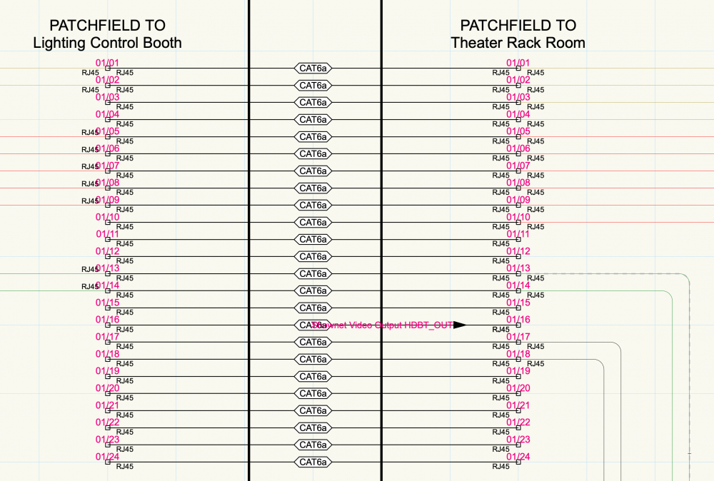
Hi Conrad, thanks for your explanation. This is a real case, yes. Attached, there is a screenshot of the actual project I'm working on. We have 2 locations connected together with 24 CAT6a connections. This is shown by 2 DTP which are connected together. And since CAT6a is not only for LAN/ethernet (bi-directional) connections, it can happen to send the data from a device to the patch panel for usage at the other location. In our case, there is a HDMI to CAT converter, which extends a video signal to use it at another location. This is directional and therefore the device has an OUT socket. But as i said, I asked for help 😉 So if I have to adjust my workflow, I'm happy to do it. I just did not find a better way? Maybe you have an advice for me? Thanks! Matthias
-
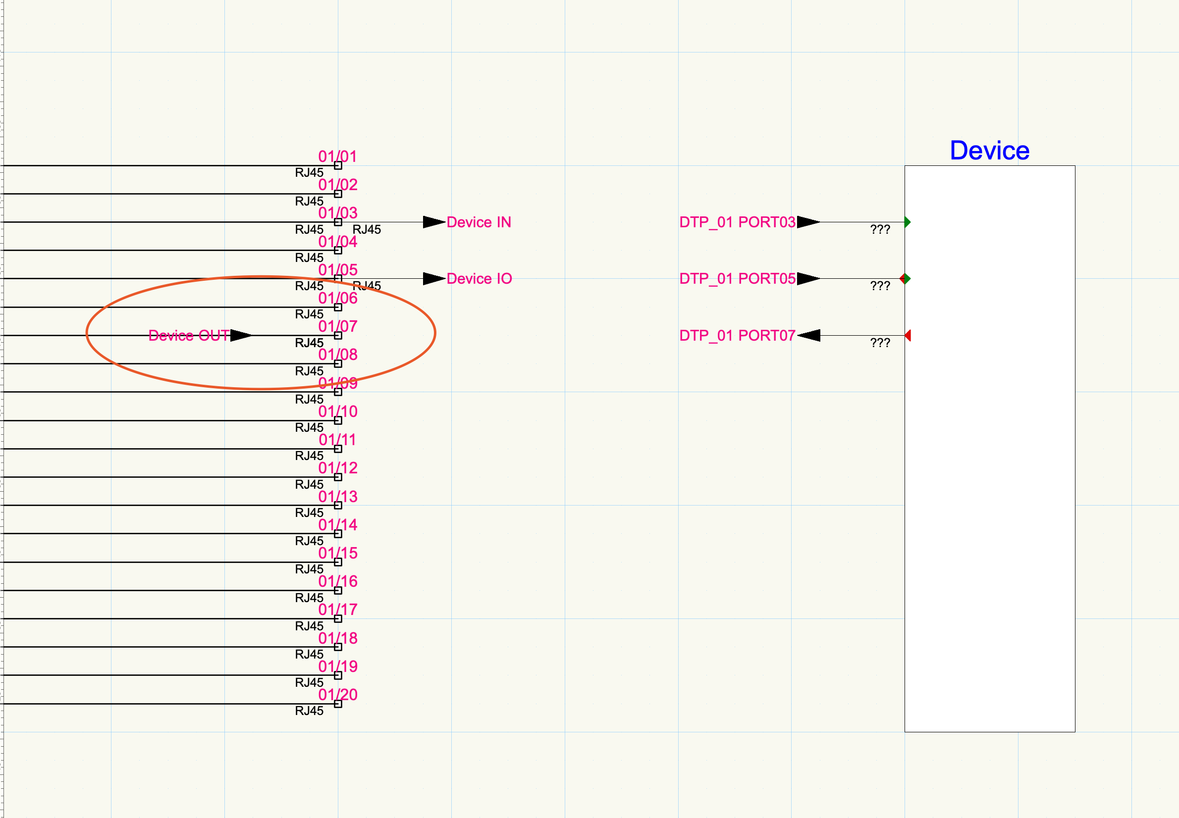
Thank you. I tired this already. But as you said: This has weird side effects 😞 See screenshot. The additional "07" could be removed by removing the tag. But the other connection still has the connector label on the wrong side. Matthias

-
Hi, can someone help me please. I'm got stuck with one thing: How can I rotate an arrow connection to a data panel socket? I know, just drawing the circuit in the other direction would solve this in most cases, but if I want a connection from a socket IN to a device OUT but to the right direction, the arrow is always placed on the right. EDIT: reshaping did not work. See screenshot and/or attached file. Thanks for your help! 🙂 Test-ConnectionOrientation.vwx

-
Grouped "Term Panel" sockets do not update circuit lines
Matthias Sch. replied to Matthias Sch.'s topic in ConnectCAD
Yes. So then the panel is a single device which can be labeled and displayed like every other device? This sounds perfect. Thanks -
I use different "LAN - ..." signal types to make plans more readable with colored lines based on what type of data/protocol the LAN connection is used for. For example: "LAN - MANet", "LAN - ArtNet", "LAN - Media". This works great because it creates different classes which can be individually colorized. Creating a defined "SignalType" in the txt file would be a big effort for lots of different types (since it requires VW to be restarted to reload the changed file). Also when using two protocols on one connection. This would make the SignalTypes.txt list bulky. Now, when I move a device, everything stays as it should. But after re-shaping a connection, the individual "Signal" entry is lost and overwritten by the default Signal coming from the connector. Steps to reproduce: - create 2 devices with at least 4 identical sockets each - connect the sockets - click on each connection and in "object info" > "general" > "signal" set an individual text as signal. - edit the new class (colorize the line) - move one of the devices > works! - reshape a existing connection > color is lost see attached test file and video. Maybe, if ConnectCAD needs to "re-create" a connection since the shape was changed, it can just look for modified signal (and remembers it, if necessary) before creating the new connection? Just like it works for cable type and and number? Matthias Screen Recording 2020-09-15 at 14.27.38.mov Test-SignalTypes.vwx
-
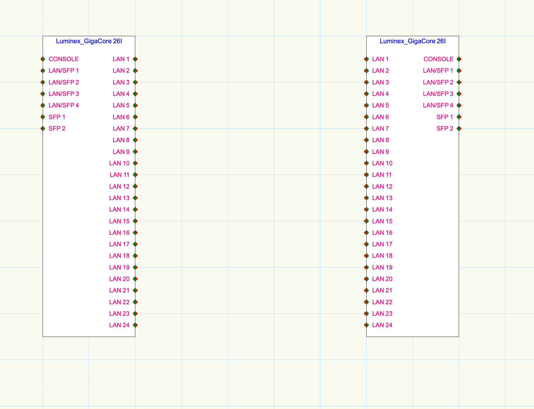
Hi there, just a quick question: Anyone has a quick way to mirror connections of a device? Like all R to L and all L to R. See attached screenshot. This is sometimes handy to swap to avoid all connections going half-way round the device. If there is no quick way (besides editing the device, change socket direction and move all sockets to the other side), this would be a nice feature: - way 1: Adding a tool or menu item to swap sides when editing a device (this would also work with devices created without device builder and also after creation). - way 2: Add a "Mirror orientation" checkbox to "Device Builder" window, which just temporary replaces the R with L and the L with R in orientation column without saving it to user folder. - manual way: just like way 2 but doing it manually. But that can be time consuming with lots of large devices. Thanks, Matthias Test-Invert.vwx
-
Grouped "Term Panel" sockets do not update circuit lines
Matthias Sch. replied to Matthias Sch.'s topic in ConnectCAD
Thanks! Ah okay, I understand. I'd like to group a rectangle, a 24 connector DTP and a label together for easy handling of a group which should look a bit more like a Cat6a ethernet patch panel. And yes, it works fine without grouping, but for easy handling I wanted to group it together to some kind of "device". Matthias -
Hi Conrad, since it is not the same thing, I opened a new topic for that: Thanks 🙂 Matthias