Stéphane
-
Posts
145 -
Joined
-
Last visited
Content Type
Profiles
Forums
Events
Articles
Marionette
Store
Everything posted by Stéphane
-
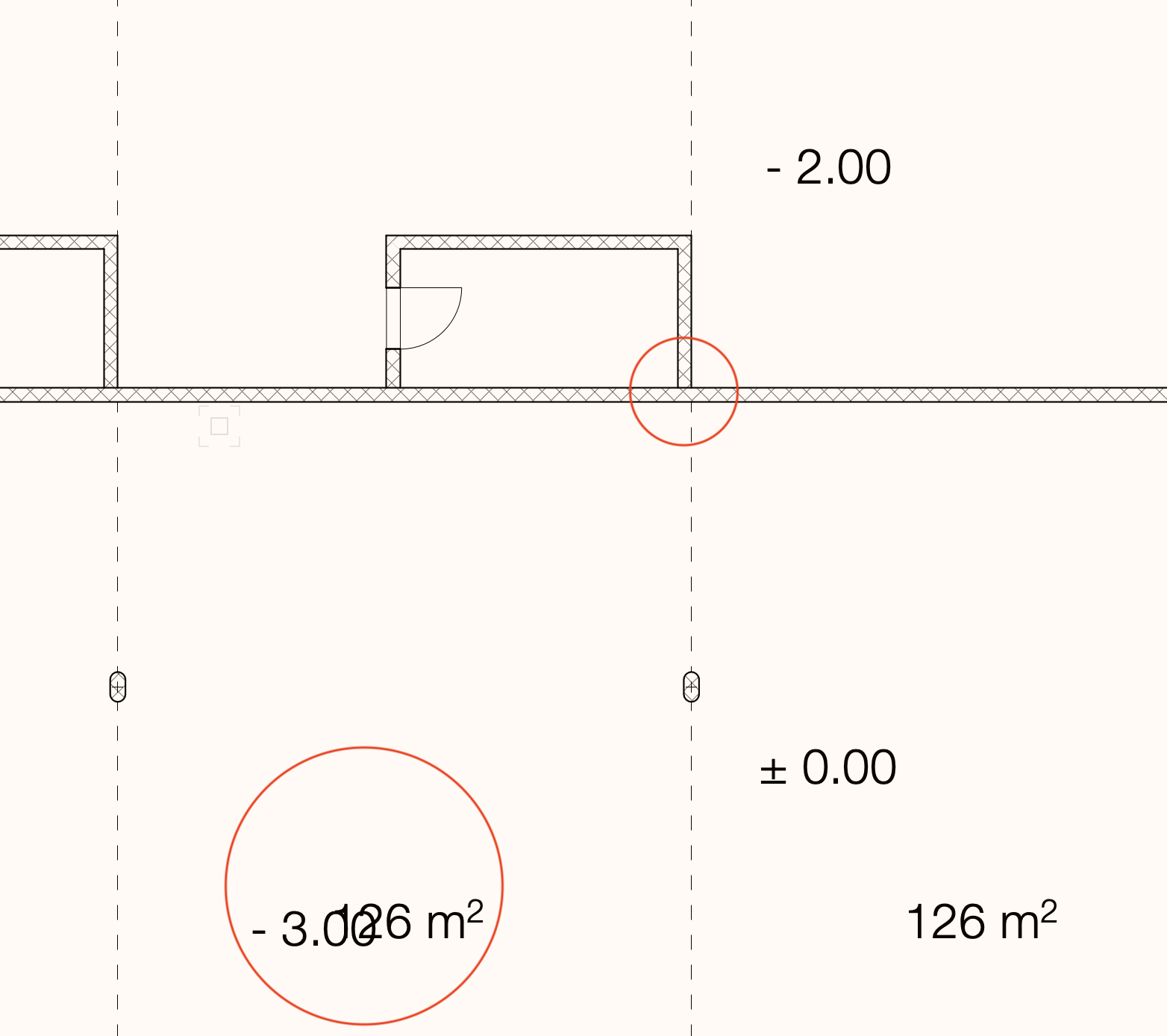
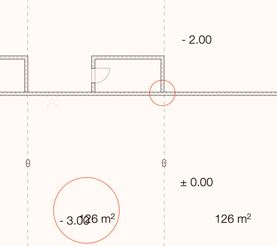
Hello, I am exploring horizontal section. 1) Why the components don't join properly (it looks like two separate walls) ? In plan they are joined properly together. 2) Why can I see the text "- 3.00" which should be hidden by the slab above on which you can see the text "126 m²" ?
-
Super nice inputs, thank you very much !
-
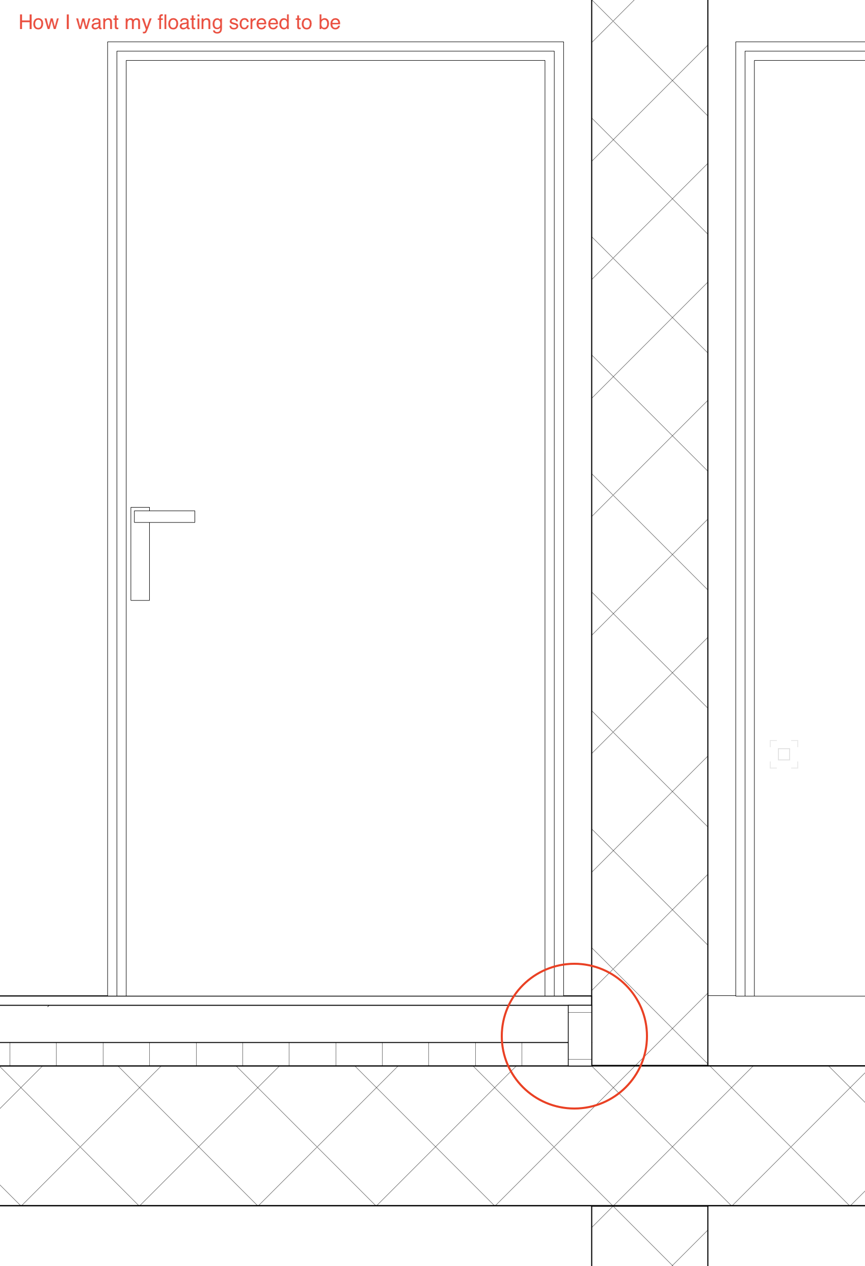
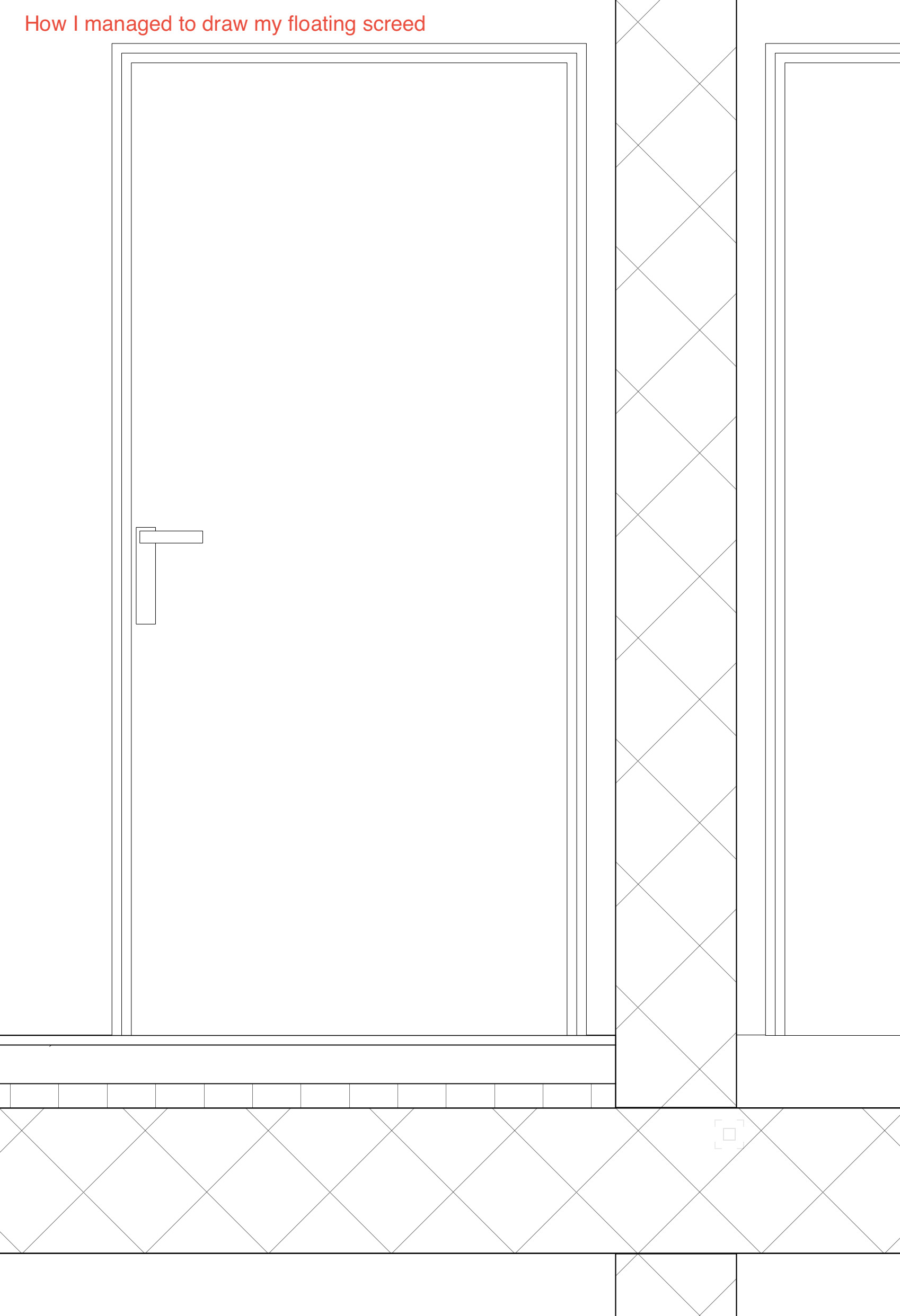
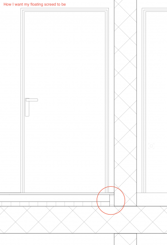
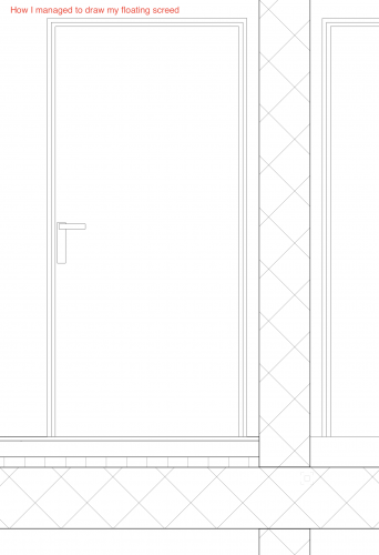
@Tom W., @zoomer, I mean everything that could be part of a floor but are vertical more than horizontal. For instance when you need to insulate your screed... See images below : I was wondering how you would do it. 3D model it ? Or patch it directly in the layout ? Or is it just going too much into details and you would produce anyway a 2D detail ?
-
After having studied several workflows, I can confirm that @zoomer and @Christiaan advices are really good. Thank you. Question : How would you create vertical linear elements in floors, typically sound insulation for floating screed ?
-

Inconsistent behavior of slabs attributes (or I am missing something)
Stéphane replied to Stéphane's question in Troubleshooting
With this solution @Kevin K, you solve the elevation thickness of the slab in elevation (under the "59200" marker), but now everything that is beyond the cut line has one single color which is your grey. It doesn't look bad tho. However (and sorry if I might be too picky), what I would like to do is being able to give more than only one attribute for objects beyond cut line (for instance grey 0.05 for the surface hatch and black 0.10 for the other objects). In this case, this means we cannot use Objects Beyond Cut Plane. If we don't use Objects Beyond Cut Plane, it means we have to be able to control lines thickness of an object when they are cut AND when they are in elevation. This is the case for walls (as described earlier) but not for slabs as explained below. After having done further tests, my conclusion, sharing @jeff prince one, is this one : Section Pen Attribute for slabs components doesn't work as expected. That's it. After all, I would say that @Kevin K way to do it, is still the best way. -
Inconsistent behavior of slabs attributes (or I am missing something)
Stéphane replied to Stéphane's question in Troubleshooting
You are too kind, thank you for your dedication. -
Inconsistent behavior of slabs attributes (or I am missing something)
Stéphane replied to Stéphane's question in Troubleshooting
Sorry for the delay. There we go. TEST FILE.vwx The thing is I want 2 colors in elevation. Grey for the hatch and black for the other lines. The green is just for the test (makes it more obvious) but it should be grey. -
Inconsistent behavior of slabs attributes (or I am missing something)
Stéphane replied to Stéphane's question in Troubleshooting
First, thank you very much @jeff prince and again, @Kevin K, for your answers. I feel relieved, since I use exactly the same strategy for the attributes in Advanced Section Properties, which means I cannot be completely crazy ! Look at my section, it doesn't. Cut wall take on their component attributes, and walls beyond section line take on the wall attributes. Based on my test, slabs don't do the same thing. (If I am not completely crazy). Okay, I am not completely crazy. I tested it and that was also my feeling. This could be a nice idea. I will give it a try. But notice that it is the 180° reverse logic compare to the walls. So, we give walls class attributes, their section lines thickness. And we give slabs class attributes, their elevation lines thickness. Then, we override the slabs lines thickness when they are cut and we override the walls lines thickness when they are in elevation. Honestly, I'm pretty sure VW want us to be crazy. Exactly. This is the whole issue with this. So, I use the same setting as you with the Objects Beyond Cut Plane setting to force each lines beyond cut plane to be thin and black. Now, I want my Surface Hatches to be grey. But they become black because of this override. Well, no problem, I untick Objects Beyond Cut Plane. But now my slab in elevation has a thick line ! This is exactly the reason why I try to solve this slab lines thickness issue. Yes, it is correct ! This issue is actually linked to the previous quote. The green is just for the test. I actually want them grey, which is also a color 🙂 Don't be sorry. I realize my whole post is arcane. You are very kind and patient. Thank you for this. -
Inconsistent behavior of slabs attributes (or I am missing something)
Stéphane replied to Stéphane's question in Troubleshooting
They are Surface Hatches. -
How to control two roof faces intersection ?
Stéphane replied to Stéphane's question in Troubleshooting
Now, I understand. I have no special edge conditions... Everything ends square. No offsets. Look, if it doesn't even work properly with simple settings, why would I want to make it even more complicated ? -
I was confused because I couldn't find "Automatic Plan" anymore but it is actually hidden until you select the 3D Locus tool. My bad. Sorry. By the way I'm happy to have learned the existence of this Analysis Tool.
-
That was it @markdd ! Super nice, life changing ! Thank you so much !
-
Another way to do it, knowing you can snap an edge or a line but not (apparently) a surface : - Draw a 3D poly from one edge of the roof to another one, going through the desired point. - Snap a 3D Locus on that 3D poly. Not as simple as I wish, but it's something...
-
How to control two roof faces intersection ?
Stéphane replied to Stéphane's question in Troubleshooting
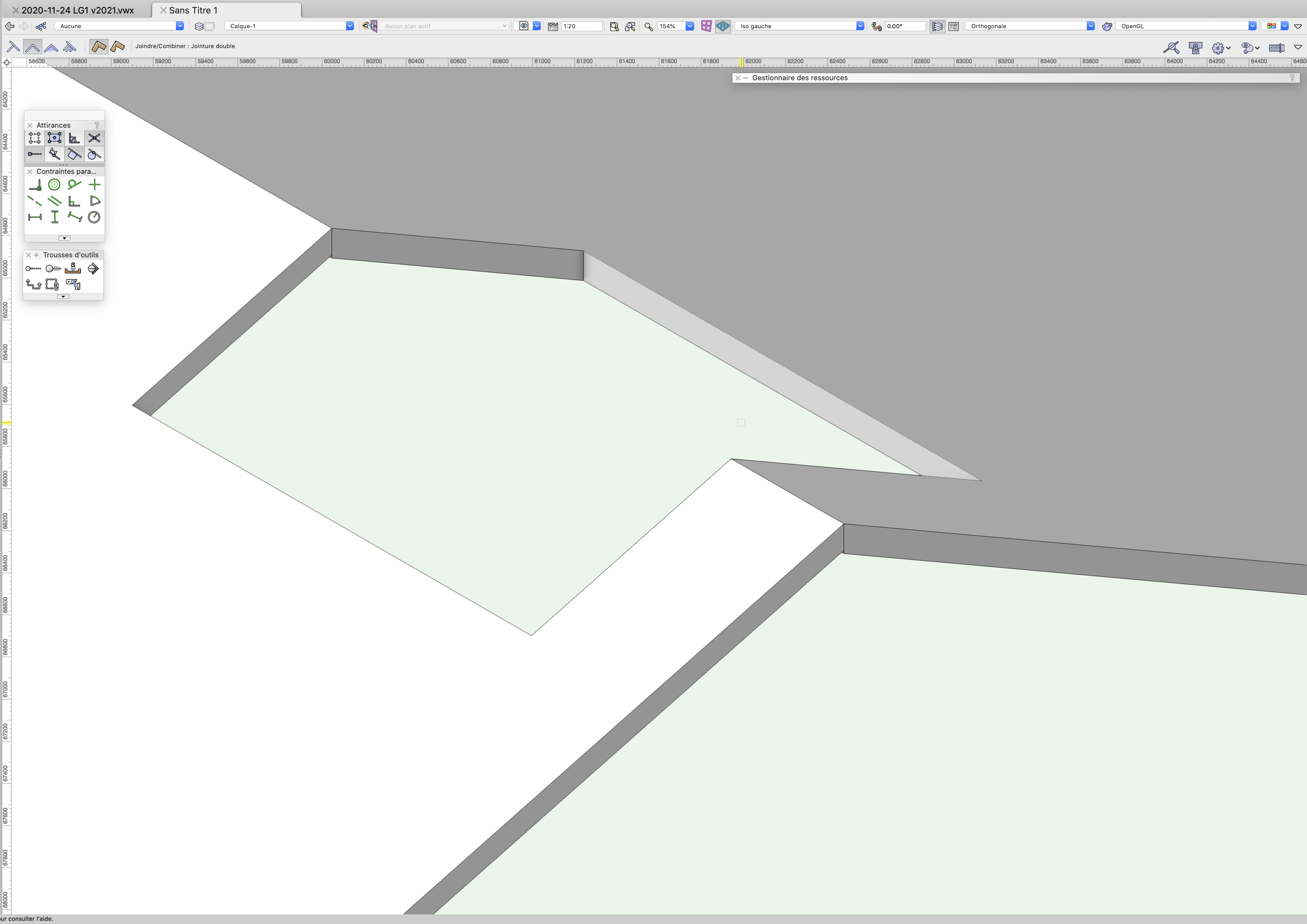
@Tom W., I'm not sure to understand your question. Edge conditions ? What I did : - draw two squares in 2D plan view - convert them into Roof Faces - give them different angles - line the top of them up in elevation - connect them with the Connect/Combine Tool -> proper mitered joints - clip a hole in them -> no more mitered joints - reconnect them with the Connect/Combine Tool -> bug -
@CipesDesign, trying to be smarter than I really am, I tried to do this with a Clip Cube in an axonometric view in order to be faster but I cannot snap my 3D Locus on the cut plane (the part that is red). Is this normal, or is it a simple setting to tweak ?
-
How to control two roof faces intersection ?
Stéphane replied to Stéphane's question in Troubleshooting
May I invite you to try connecting these faces as shown below ? TEST_connecting roof faces.vwx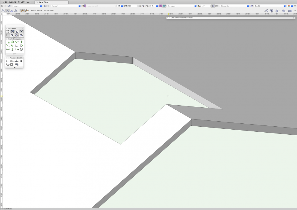
-
Great suggestions, @CipesDesign and @markdd, thank you ! Sometimes the solution is out of the box. I still believe that it could, ideally, be more straight forward, but at least I can move on now.
-
Inconsistent behavior of slabs attributes (or I am missing something)
Stéphane replied to Stéphane's question in Troubleshooting
So, absolutely nobody in this world has the same issue ? Or the whole world print their elevation with the wrong thickness ? I am surprised by your silence. -
I have a roof. I want to measure the height of it at a specific point somewhere in the middle of its surface. How to achieve this ? What I used to do until now is use the 3D Locus Tool, click in the middle of my roof, select my 3D Locus, write down its Z value. It doesn't always work anymore. Beside this, I don't understand why something that should/could be simple, is so complicated. My general goal is to set the Z values of my pillars connecting two tilted geometries. If you have an easier way to achieve this, you are most welcomed !
-
How to control two roof faces intersection ?
Stéphane replied to Stéphane's question in Troubleshooting
I think @Tom W. summarize pretty well the extras here : And this is exactly why I prefer the Roof Tool over the Slab Tool to make my underground parking slabs, where drainage slope are not negligible anymore, and easier to do. -
How to control two roof faces intersection ?
Stéphane replied to Stéphane's question in Troubleshooting
It's a bit the same issue we have for connecting roof faces properly : It works only for simple structures. When you get a more complex one, best case : you spend a whole day making it work exactly as you want to; next day your engineer send you an e-mail saying that you cannot and need to spend another day to correct it. Worse case : it doesn't work. This exemple sounds a bit stupid but that's actually the very reason why you don't solve these issues at the beginning of the project. And that's why we need to be able to draw drained slabs or roof completely flat, first. When the project is getting stable enough, you start going into the details. -
How to control two roof faces intersection ?
Stéphane replied to Stéphane's question in Troubleshooting
I would never yell at someone that is kind enough to share his experience. In order to answer to this, I think the question here is not that much how to build roofs, but how to draw roofs. The original topic : "How to join two roof faces ?". We found out that it was possible to do it for simple structures but not for complex ones (where "complex" stand for 1) roof with a hole; 2) intersection not perpendicular to the edge; 3) 0.000000° flat roof). This means that most of the times the tools to join roof faces are not usable. We all agree that flat roofs are never completely flat, because water need to drain and requires a minimum slope of 1.5%. When we say flat roof we actually say 1.5% tilted roof (Note that this 1.5% slope is not necessarily the last layer). For drainage it is not negligible; but for the drawings up to 1'':10'00'' (+/- 1:100) it is completely negligible. On bigger scale, we draw 2D details anyways. There are many reasons why we want to draw dead flat roofs : - As said, when we draw on small scales, at early stage of the project, where you still don't want to think about these details. - Then maybe, the first component and the last component are dead flat. The slope is given by a component in between. - Imagine you are crazy enough to draw your slope with the Drainage Tool on Slab, then you draw your slabs (which would be your roofs) completely flat and you give then the drainage slop with the Drainage Tool. Also, keep in mind that we actually draw tilted slabs with roofs because the Drainage Tool is a nightmare to use (I would say the issues are a bit similar to our "how to join two roof faces": it doesn't work when things are getting complex), but this is another topic. - The main reason is this one : tools are not usable to control slopes accurately ! And this is again why you don't draw your flat roof with a drained slab. I cannot agree more, with a reservation regarding the Drainage Tool ("sloping the surface") which is, in my opinion, unusable.- 94 replies
-
- 3
-

-
- roof
- combine/connect
- (and 1 more)
-
How to control two roof faces intersection ?
Stéphane replied to Stéphane's question in Troubleshooting
I encountered the same issue when joint line is not perpendicular to the edge, exactly as you did. In case of a hole in the middle of the joint, it is even worse. -
How to control two roof faces intersection ?
Stéphane replied to Stéphane's question in Troubleshooting
Thank you very much, @Tom W., for your input. I did the very same test you described, and it works very well and everything is very nice, indeed. The only thing is that the structure you made is very simple, and it doesn't work so nice anymore in more complex situations. I could also live with a "flat roof being 0.1 degree". But this is not the only issue. For instance, add a hole in the middle of the joint and it won't work anymore. At least in my experience. -
How to control two roof faces intersection ?
Stéphane replied to Stéphane's question in Troubleshooting
Last thing we could do is ask @Matt Panzer for some inputs maybe...