


Stéphane
-
Posts
145 -
Joined
-
Last visited
Content Type
Profiles
Forums
Events
Articles
Marionette
Store
Posts posted by Stéphane
-
-
@Tom W. Pretty nice solution, thank you ! I have tested it and it looks much more efficient than these wall features.
@cberg Thank you for your honest answer. "If it sounds painful. It is. And we've all been there. " Somehow, that comforts me, thank you.
I think I'm going to do a mix of your solutions : I will only split the insulation part as Tom W. suggested it and class it amongst everything that is under the slab and deactivate it in plan. Instead of duplicating the openings, maybe I could just split the wall above them and offset the bottom accordingly.... Need to test this.
-
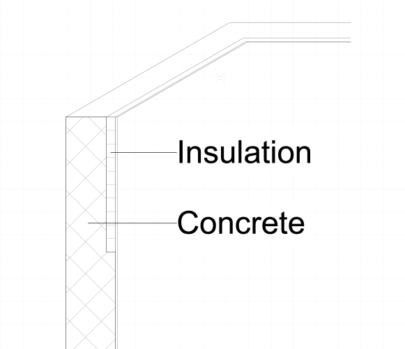
Hello,
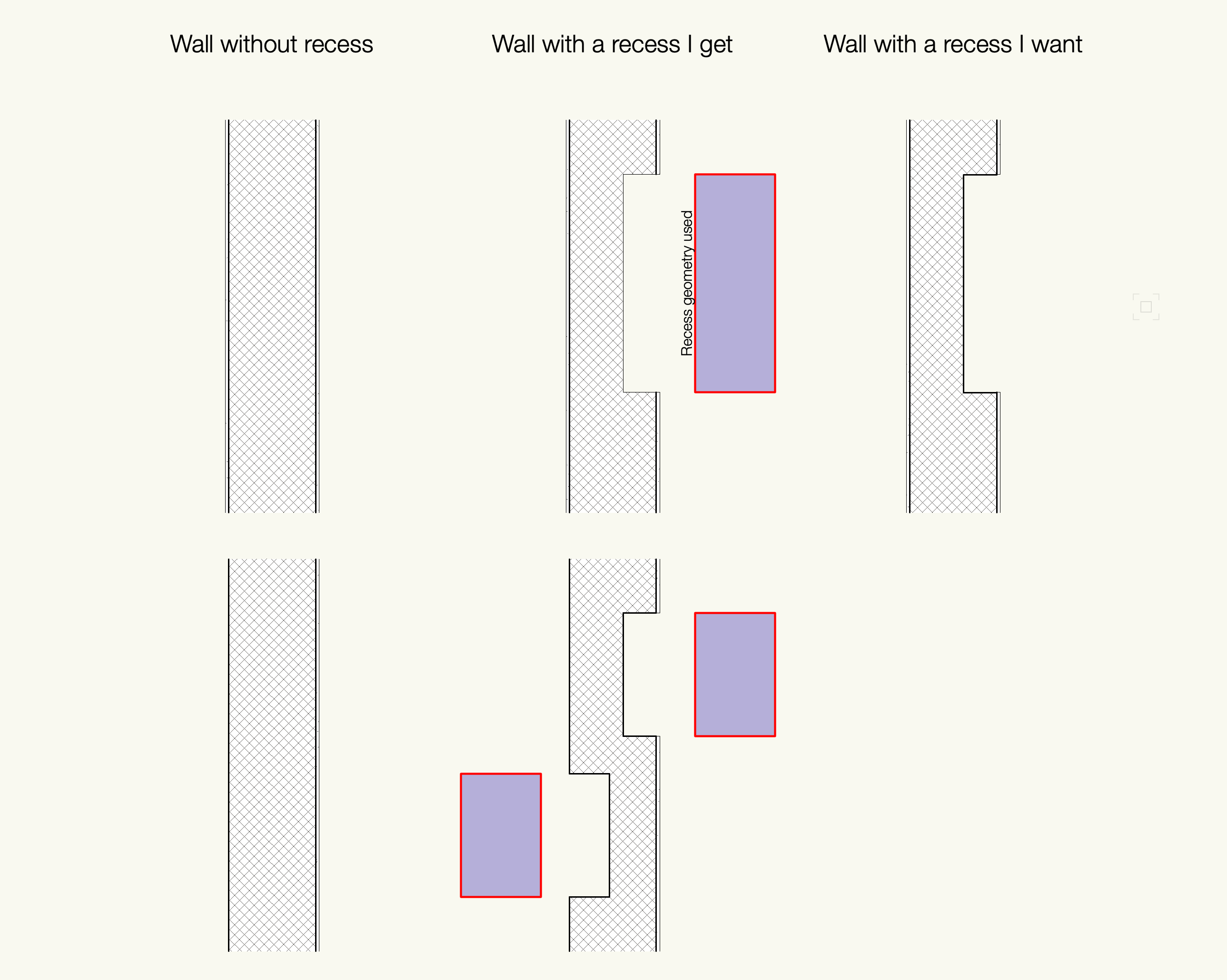
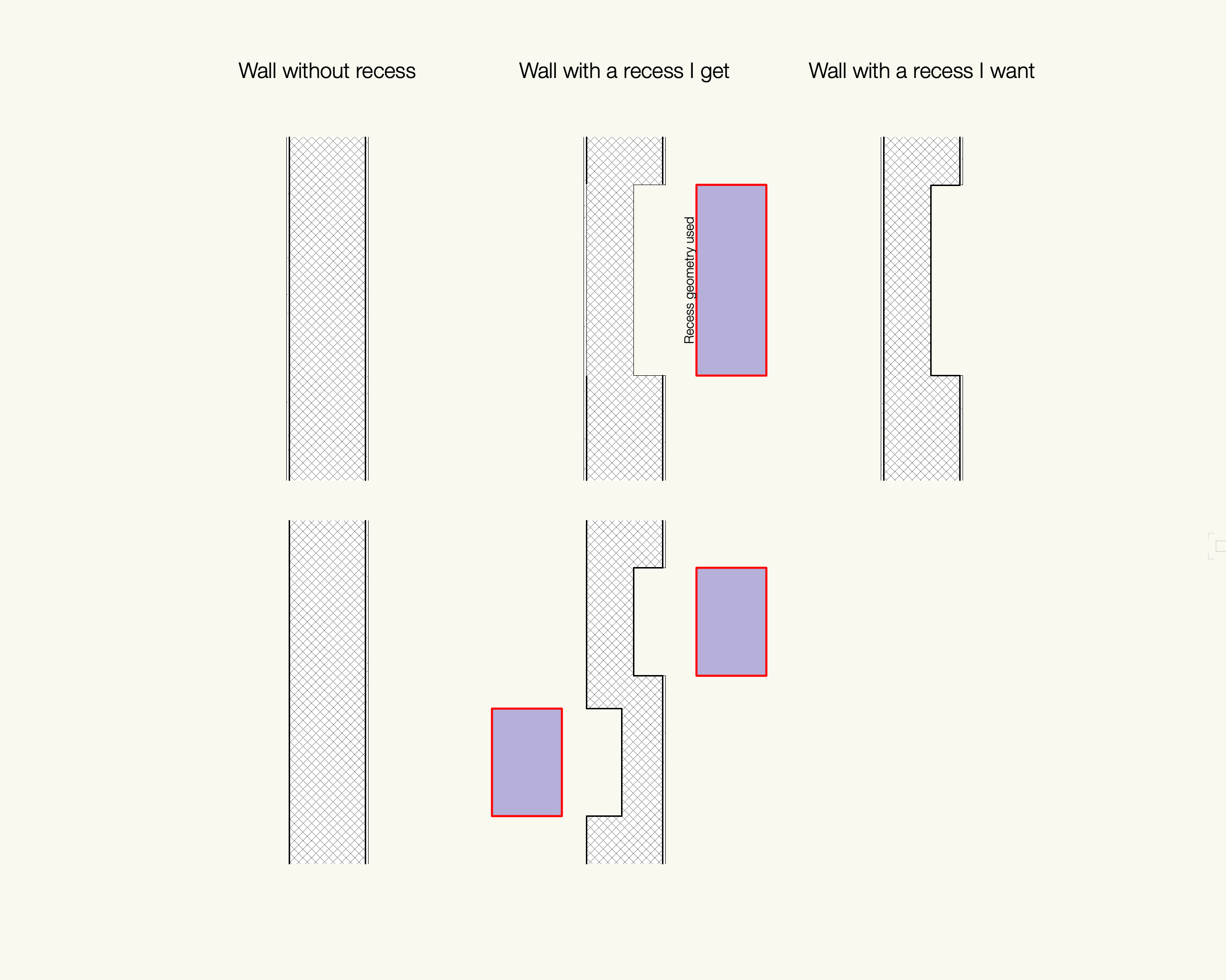
I would be glad to get your precious hints on my issue. Since one drawing is better than one thousand words, please find my issue below 🙂. How would you draw such a wall ? I tried walls features but I have 2 problems with them :
- difficult in the angles
- somehow refuse to show the hatch I want, always shows the extrusion filling attributes in a hidden line section viewport (so it is always a solid color with no contour
-
@Tom Klaber You described exactly what I experience when I do OpenGL renderings in VW2021 SP5. What I observed :
- Memory pressure stacks after each renders. When memory pressure reaches 34 GB, VW crashes.
- Save, quit and restart VW release the memory.
- My routine to prevent a crash when I do OpenGL renders : 1. No more than 5 renders. 2. Save, quit and restart. 3. Back to point 1.
- I lost a keyboard last Friday because I did 7 renders before saving and had to redo everything 🙂
-
 1
1
-
-
Still an issue in VW 2021. VW doesn't release memory after an openGL rendering. I have to save&restart after 10 pretty basic renderings.
-
Thank you very much for this, @Pat Stanford. I will share here the conclusions for other VW CH_FR users (Potentially 2.2 mio users 🙂)
1) My door is a 'Door CW' not a 'Porte'
2) The fields in the OIP are actually translated from German. So you need to call them in German.
3) The IFC fields are always in English.
4) If you click on the little arrow in a cell and select "Database" and the PIO you want ("Door" or "Window" or whatever) you will find a list of all parameters you can use.
So what I was looking for was :
='Door CW'.'BaseQuantities_Height'/10 (/10 because BaseQuantities are in mm but I work in cm)
='Door CW'.'BaseQuantities_Width'/10
='Door CW'.'Türhöhe'
='Door CW'.'Türbreite'
='Window CW'.'BaseQuantities_Height'/10
='Window CW'.'BaseQuantities_Width'/10
='Window CW'.'Fensterhöhe'
='Window CW'.'Fensterbreite'
-
2
-
-
Hello there,
Awesome explanations, @Pat Stanford, thank you for that.
My VW is set in French and
=(Door.Width)
doesn't seem to work. I use a PIO which is called Porte. In the OIP there is a field called "Largeur de la porte"
=(Porte.'Largeur de la porte')
doesn't work neither.
Questions :
Does your trick work for each PIO ?
How do you get the name of a PIO ? Is it the one written at the top of the OIP ? Is there an official English name hidden somewhere ? -
@Matt Panzer Thank you for your feedback. I haven't updated to VW 2022 yet; Have you tested it in 2022 ? -
15 hours ago, Matt Panzer said:
Can you attach a the file?
Thank you @Matt Panzer to have a look into it :
-
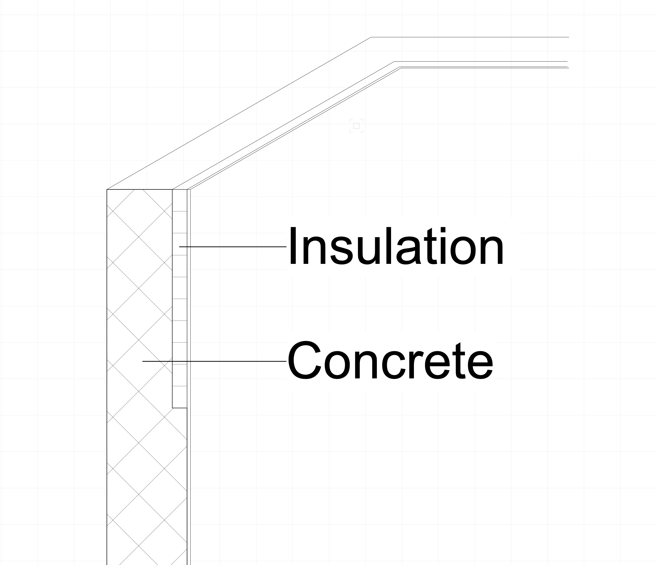
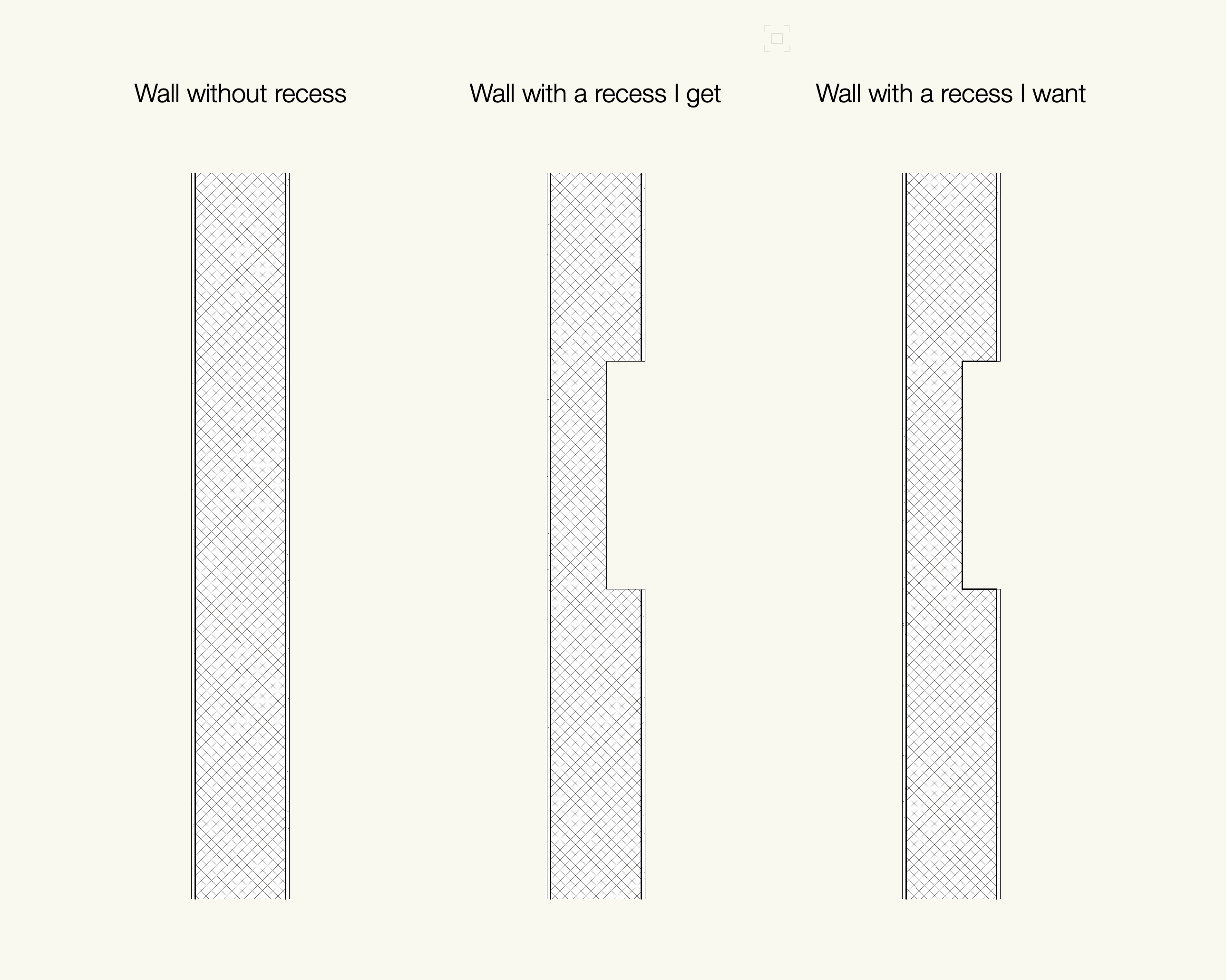
Progress has been made... I added a line to both side of each component in component settings. Still 3 thick lines missing in the recess.

-
12 hours ago, zoomer said:
Is the recess maybe driven by the recess geometry line styles (?)
(Or coming from overall Wall line styles ?)
That was my first guess, but no.
First line is finishing-concrete-finishing. Second line is concrete-finishing. No issue with this one. Weird, isn't it ? See below.

-
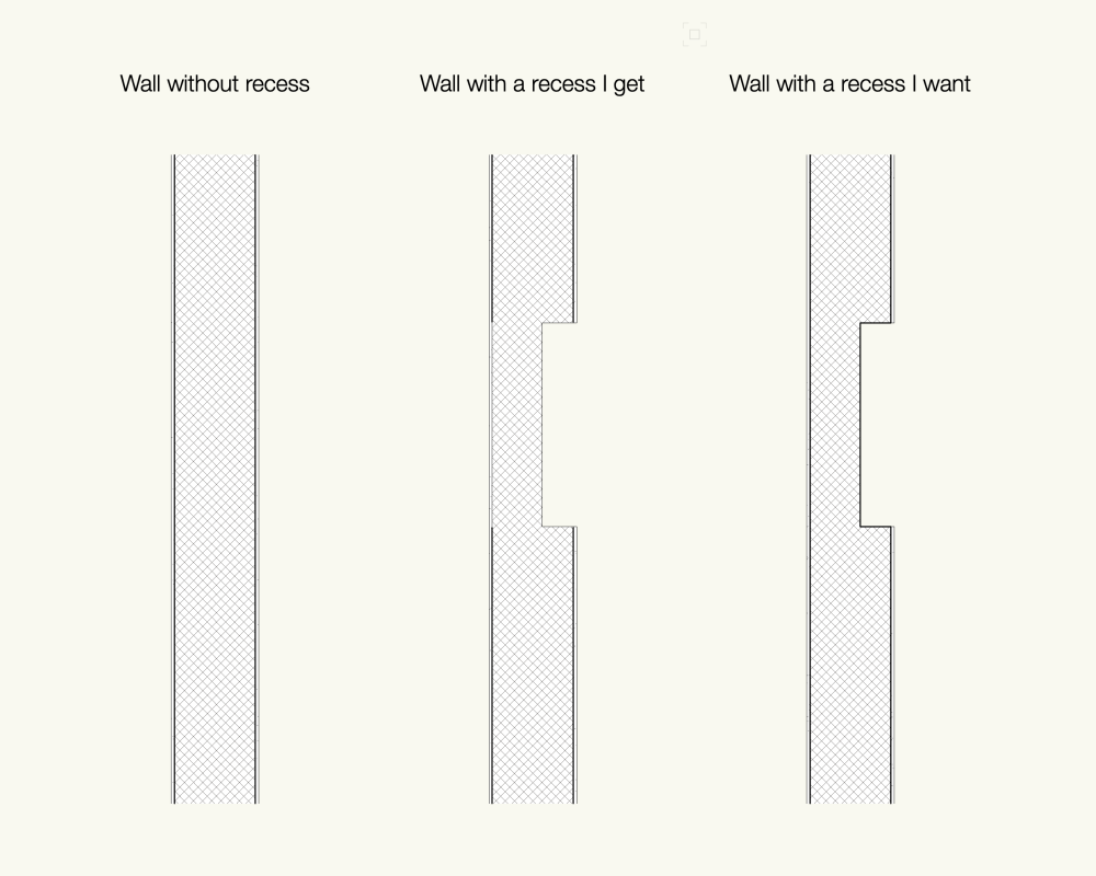
Hey,
May I bump into this topic with a related issue ? I tried the feature technique with a multi components wall and my lines thickness get messed up. See below. Any hints ?
-
Having the same issue in VW 2021 on a 2D plan VP. Hasn't it been fixed yet or am I missing a new tool maybe ?
-
Having the same issue on a 2D plan VP. Hasn't it been fixed yet ?
-
I should have added that only the barriers lines vanish. The barriers texture/fill shows up.
-
This is a very specific issue :
When I create a section VP with a section line with at least 2 vertices, going through a custom staircase with a barrier, then the barrier doesn't show up.
When I remove the vertices from the section line (becoming a standard linear section line), the barrier shows up again.
This is at least true in hidden line, and realistic VPs.
Now, who's guilty ? The section VP, the custom stair (known to be very buggy), or the user ?
-
I cannot figure out why my walls are transparent in hidden lines renders. May need a hand on this one please.
In Artistic and Realistic RW, they show up... but not in hidden lines.
-
Is the issue solved in VW 2021 ?
-
59 minutes ago, Stéphane said:
Is there another handier way to create a slab with an editable hole without modifiers ?
My mind has been refreshed :
Draw a Slab -> Right click, Edit Boundary -> Clip your shape in there -> Now you have a geometric hole.
Notes with this method :
- When you are in the Edit Boundary space you still don't see the visible environnement. Once out of the Edit Boundary space, you will be able to adjust your hole with its context tho.
- Don't know how it behaves with multicomponent slabs recess.
- A modifiers hole can still overlap a geometric hole.
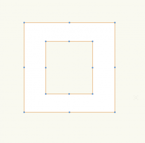
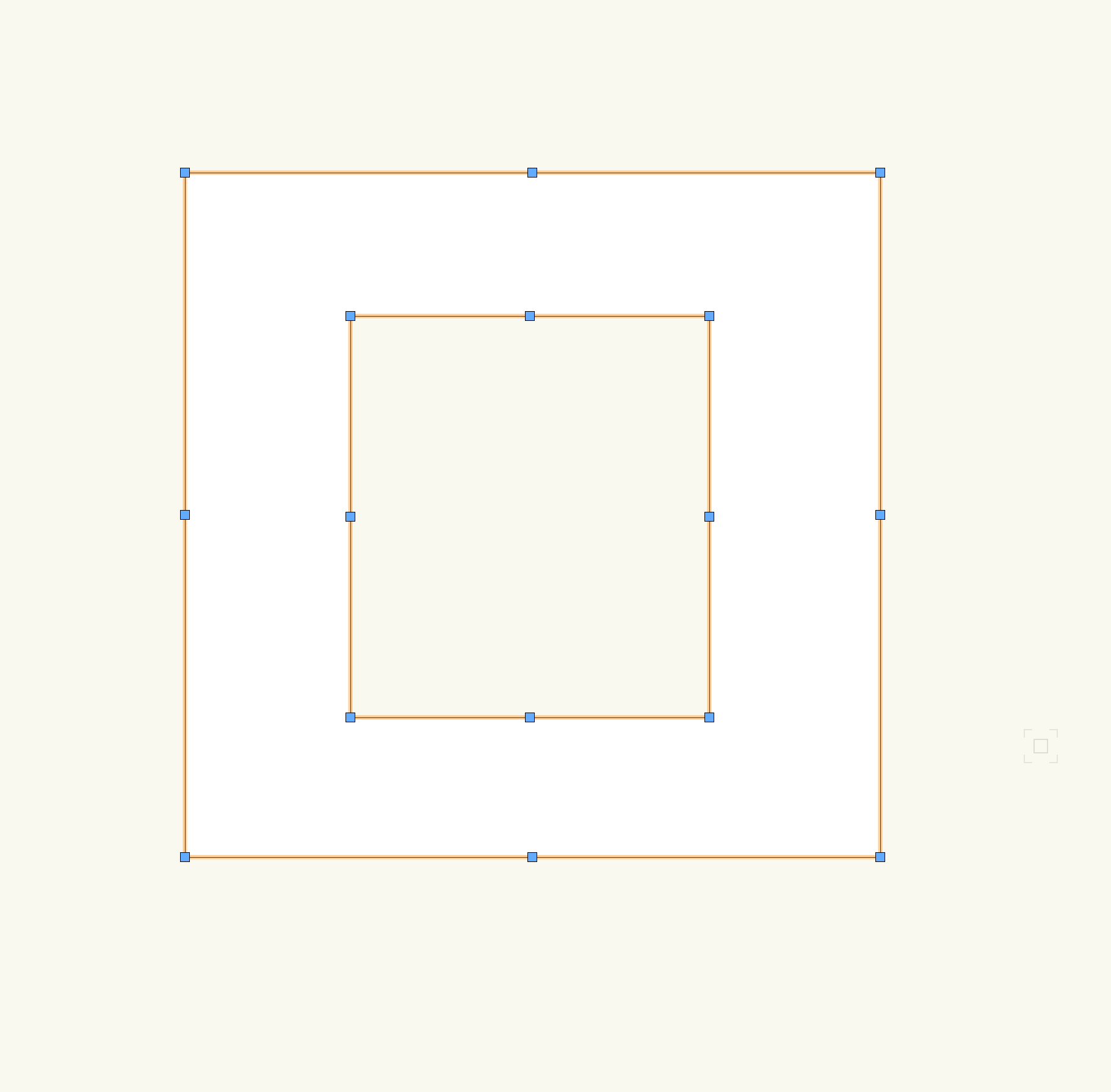
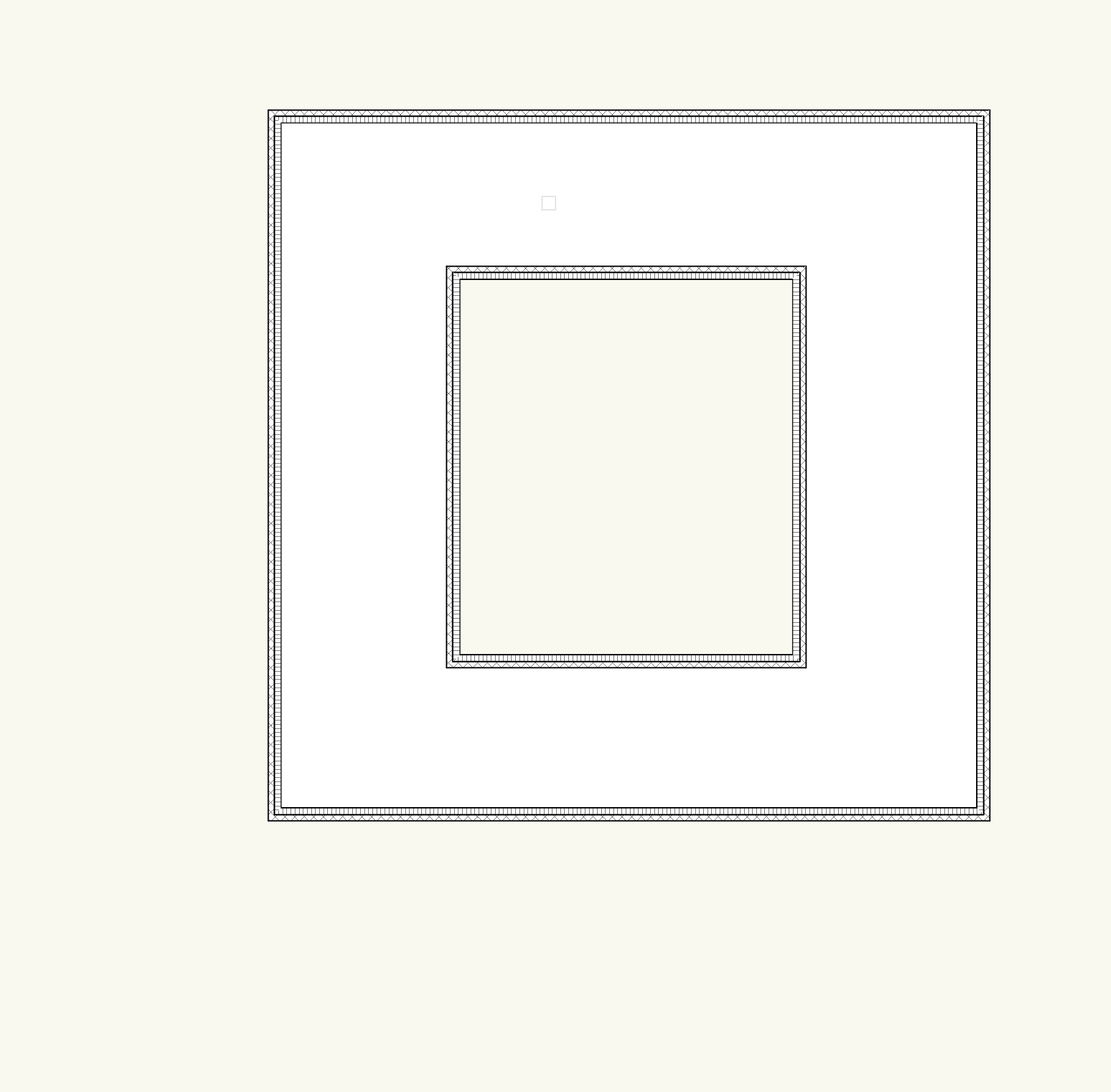
PS : What I call a "geometric hole" is a hole that has no modifier and is editable without entering in the Edit Modifiers space as shown in the picture below. Hope it is clear enough.
-
2
-
-
Thank you for your answer.
Some inputs after having done some tests. Here are three different ways of doing holes in a Slab :
1. Clip tool on a slab. Modify it via Edit Modifiers.
2. 2D shape on a slab -> Select Slab + 2D shape and then Clip Surface as Pat suggested it. Modifiy it via Edit Modifiers.
Now :
3. Create Slab with Inner Boundary mode
 . This requires to have walls. Remove walls. Now you can edit the hole without entering in the Modifiers space via the reshape tool (or double-click on the slab). In this case there is no modifier. This is nice because a) you see the environnement b) it is straight forward.

Funny story :
I have actually such slabs in my drawing and I have no clue how I created them and I cannot reproduce them (and I am pretty sure I haven't created them with the Inner Boundary mode which is painful; hence my question below).
Question :Is there another handier way to create a slab with an editable hole without modifiers ?
-
May I pop into this topic with subsidiary matters ?
When I need to edit a shape in the Edit Modifiers space, I realized two things :
- I cannot actually edit a shape; I need to delete it and recreate it through the clip tool (pop up window says I cannot create a new shape, since my edited shape is considered as a new shape)
- When I want to edit the slab geometry or the slab modifiers I cannot see the context (usually greyed out like when you edit groups) which makes it difficult to edit them.
What am I doing wrong ?
-
Why don't you draw your fire compartment polylines in the annotation space ?
-
I thought Walls components textures would work a bit like Windows where you have "by instance"

 and "by style" settings. Apparently, this is not the case. For a styled wall, if you click on the Components button in the OIP, you will find out that you can change the top and the bottom level of the component but not its texture which is greyed out. I was wondering if I missed a setting, but you are telling me (as far as I understood it) that this is the normal behavior.
Might be a wishlist thing ?
-
Interesting inputs, thanks to all of you !
-
Thank you for your answers.
On 11/29/2021 at 11:00 AM, Tom W. said:You need to convert the wall to Unstyled in order to override the by-style component textures
So it is not possible to set the texture of a styled wall "by instance" ?
To further develop my issue :
I have a styled wall (concrete/isolation/coating). From one wall to another I would like to change the color of that coating. If I have a wall with a blue coating and another wall (same components) with a white coating, I need two different styled walls (ie concrete/isolation/blue coating and concrete/isolation/white coating) ? Is that correct ?
Export to DWG 2D
in Troubleshooting
Posted
Hi,
I have the same issue, but I couldn't solve it.
My file structure :
- Class for slab objects
- Class for wall objects
- Class for each component used in slabs and walls, sometimes I use the same class, for instance "Concrete". They are set so visible.
Now, if I set the class "Concrete" to invisible, it removes the unwanted hatch of the slab objects in the exported DWG, but it also removes it from the walls. I want the components hatches removed from the slab objects but not from the wall objects. When I export the layout to PDF I don't have this issue : Slab objects don't generate their components hatches, because they are not cut. I would like my DWG to be exactly like my PDF.