Ross McLee
-
Posts
120 -
Joined
-
Last visited
Content Type
Profiles
Forums
Events
Articles
Marionette
Store
Everything posted by Ross McLee
-
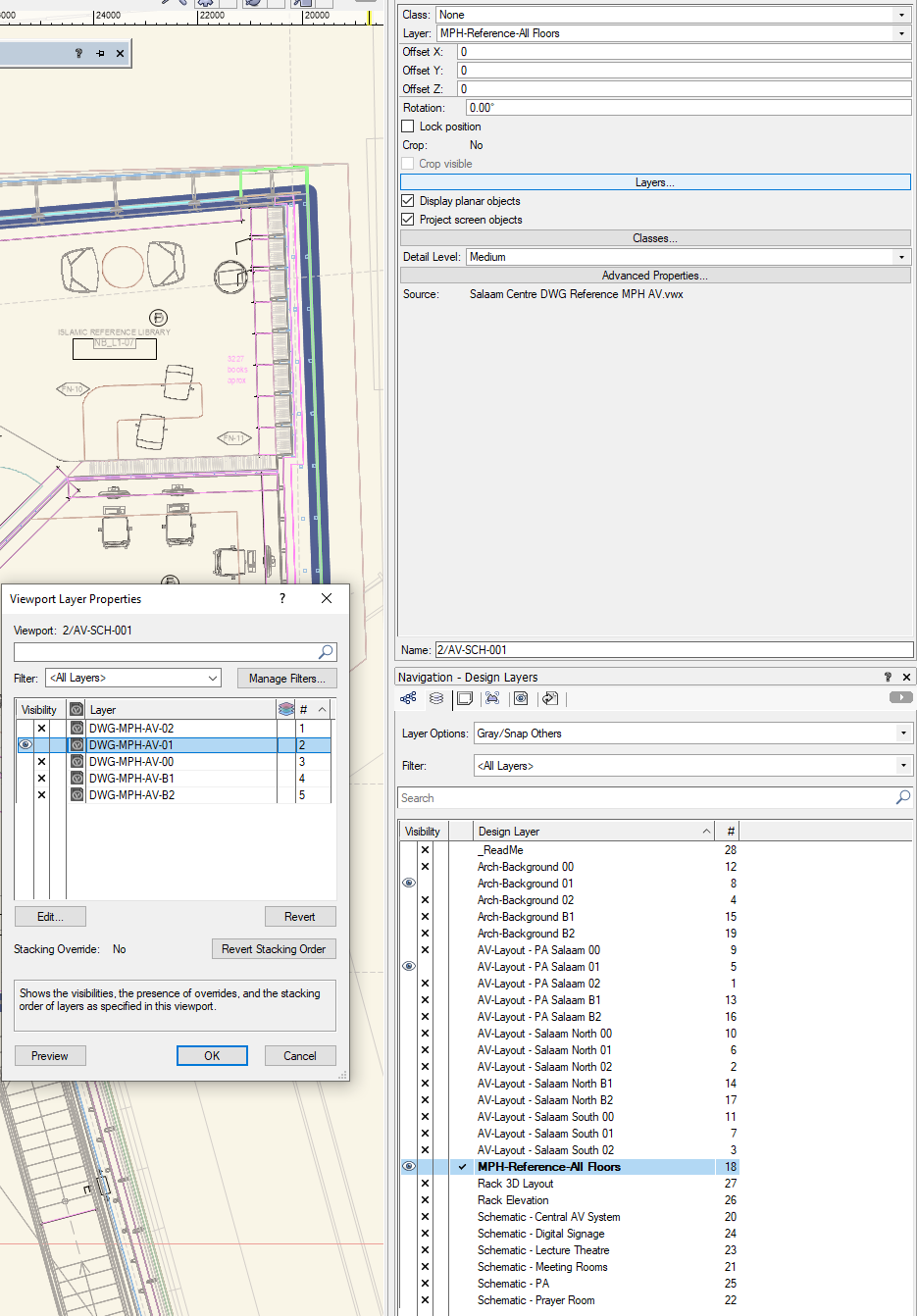
Hi, On recommendation from forum discussions - I have created a single VWX file which contains 5 layers. Each layer has a different DWG file imported (not referenced) onto it representing the content for the 5 floors of my building. I then reference this file into my main VWX drawing. By using the OIP I switch the viewport visibility of the referenced layers (for each floor) in conjunction with the specific floor layer(s) that I am working on. This is great and has improved performance (compared to importing/referencing all 5 DWGs directly into the main file). I need to remember to set the active layer to the reference file layer to select the viewport and change the layer visibility, then change active layer back (I mainly like to use grey/snap others!) I have been using saved views for a little while now, and love how they speed up switching layers and visibilities, however I would really like the ability to switch the viewport layer visibility (classes too perhaps, but not relevant in this particular case). So in this scenario a saved view for the first floor would set the active layer to "My First Floor", "Architect Level 01" ON, "Reference file" ON, "Viewport / Reference File - Layer Level 01" ON (all others off). Grey/snap others. Is this even possible?... I don't know. 🙂 Thanks, Ross
- 1 reply
-
- 1
-

-
- saved views
- references
- (and 1 more)
-
We have a limited number of network licenses for our small team. Sometimes we just need to review each other's work, so the free viewer seemed like a good idea... however: The viewer install overwrites/reuses the local user setting folder for vectorworks so I have lost my personal settings. The executable appears as the same name in the (windows) start menu so it is difficult to tell which app you are launching The default app to open vwx files is set to the viewer. After launching the viewer app the license settings for VW 2021 are lost and need to be re-entered. I'm sure there will be other similar effects from the 'duality'. I would strongly recommend that the VW Viewer is considered as a standalone app and not piggy back on existing installations. The support team in the UK were, as always, great in fixing this. Thank you. R
-
Hi All, I realise this is a known 'thing', but I was curious to know what plans there are to rectify/accommodate it... Example: In the case of a microphone connected to a DSP you could have a MIC signal going into a MIC/LINE signal type input socket. The signal here is MIC but the report (and error check) will display an error/??? . This scenario gets even more 'interesting' when we connect the likes of LAN, LAN (PoE), Dante, AES67, video streams etc over ETHERNET and all the devices are connected to a switch with signal type LAN. Same goes for LowZ and 100V line speaker levels. And many more! Without wanting to spend a lot of time maintaining matched signal types at both ends, is there something in the pipeline to allow for some sort of multilevel signal type matching (based on signal/level protocol, or something like that!). Cheers, R
-
Project Sharing: Save and Commit option when exiting
Ross McLee replied to Mickey's question in Wishlist - Feature and Content Requests
2021 - New user and still can't see the option to save and commit when exiting (or indeed just saving the local working file). Would make sense! -
So create a report on "equipment items" instead of "devices" .. ! that would work. Not sure how I would sync the quantites of equipment items to the label in the schematic automatically, if the design changes. But I'll give it a go. Thanks CP.
-
Hi all, I was after some advice on best working method for drawing an installed distributed audio systems (PA) for buildings. I'm trying to avoid taking up huge amounts of drawing space showing hundreds of loudspeakers (lots of 100V line) all of the same type, which is not very meaningful, but I still want to schedule the quantities and locations etc. Any best working methods, welcome! Thanks, R
-
Different page (paper) sizes for different sheet layers
Ross McLee replied to Ross McLee's topic in General Discussion
Even better, really handy to know - Thanks Pat. -
Different page (paper) sizes for different sheet layers
Ross McLee replied to Ross McLee's topic in General Discussion
Thanks Tom! I never noticed that in sheet layer setup window!.. I have always gone through the file, page setup option, which I assume afects all pages?.. Either way - Sorted! 🙂 R -
Hi, Newbie question: Is it possibly to have different page size settings for different sheet layers? For example: I would like to print of reports/worksheets on A4 or A3 sized paper, Schematics in A3 or possibly A2 or larger. Layout drawings (GA's, elevations, sections etc) on A3, A2, A1 or even A0 depending on the scale required. If it is not possible, then this will definitely go in my feature request list. Thanks, R
-
AutoCAD XRef Clipping boundary equivalent
Ross McLee replied to Ross McLee's topic in General Discussion
Thanks Markdd, I was more interested in clipping the content in the design layer... E.G I have been sent some architectural drawings which show multiple spaces (section and plan) (on different levels) in one DWG but the spaces should really be put on different design layers. So clipping them to hide the irrelevant content (minimise their memory use) would be good and have multiple references of the same file in multiple design layers. Does that make sense? R -
Hello good forum people, As a new VW user and transitioner from ACAD... I like the DWG import functionality within VW but would like to know if I can limit the amount of information imported or at least what is displayed. ACAD uses XREF clipping boundaries, is there an equivalent in VW? I think in ACAD it also reduced the amount of memory required for the Xref itself so a performance enhanser. Thanks, R
-
I hadn't appreciated the "Update Rack Elevation" was in fact the tool/command I needed. The video was a bit misleading (but you can blame Tom for that ! 🙂 ) I've used that and getting the hang of how it works. As for the upcoming stuff from your Lab - We are poised and waiting. Should you wish us to play as beta testers etc, please drop me a line. R
- 7 replies
-
- 1
-
-
- device
- equipment item
- (and 1 more)
-
Conrad, I'm sure you have received lots of input on cable types and signal type associations... so here is my +1 🙂 Consider multicore cable types which carry power, control and possibly A/V signal together and how that is split at the sockets. I echo comments above and suggest that limiting the cable types to choose from in a drop down list for a given signal type would be good, reducing the time to select the right one and reducing errors (eg. can't put 240V AC down a twisted pair / CAT5). Being able to add/change the cable type through a report would be great. E.g select al the data cables in a project within a worksheet and set to CAT5... then be advised that the building infrastructure is CAT6, then a simple change in the worksheet fixes that. I appreciate all the work you and the team are putting into this great product. R
-
Power and data outlets linking with schematic and scheduling
Ross McLee posted a topic in ConnectCAD
Hi, (NEWBIE VW2021/ConnectCAD) - transitioning from ACAD. Our AV schematics normally show the power and data outlets we need to be provided by another contractor (electrical/ICT/main contractor etc) to install (either in a floor box, under the floor, in a wall outlet or even in the ceiling. The same goes for power outlets. What is the recommended Vectorworks workflow to not only show these outlets in a schematic but to synchronise them with the outlets shown on a floor layout (both ways)? (I guess that also applies for other devices that are located in a room not just rack based things - like a projector) The schematic will need a device or similar symbol to represent it, and the layout will need a 3D representation of the object so it can be detailed in elevations etc, and a (low detail) symbol so that the electrical contractor can design their package. Then all of this needs to be scheduled (including the location of the outlet either floor, wall, ceiling etc..) Thanks, Ross -
Is there a detailed workflow article /tutorial on allocating locations and racks for devices within a schematic? Tom did this video but skipped over the process of "Creating Devices from List" (and I can't work it out) and can't fin any info on-line The video suggests that this is a workflow you do at the end of the design process, I'd like to know how it can be updated iteratively too, if you add/delete items from the schematic, how do you keep everything in synch?
-
Could someone clarify how these files work collectively... If you have the default (as installed) files, user edited files in the user folder AND the workgroup file. Does a single file take precedence? Are they merged and duplicates removed I notice the connector types (and the signal types) are not in alphabetical order - So I'm going to sort that shortly, but wanted to know how VW opens and uploads the data into ConnectCAD. I'd also echo a previous poster's comments that having to restart VW for the changes to be implemented is a big no-no :-(. Being able to edit these txt files from within VW would be much cleaner too! Thanks, Ross
-
Importing DWG with dynamic blocks with text attributes
Ross McLee posted a question in Troubleshooting
Observation: When importing a schematic I drew in AutoCAD the text attributes were not importing correctly. We use blocks (much like the ConnectCAD devices symbol - in fact the block in question is called "device") to represent equipment used in AV systems. The blocks had text attributes representing the device name, make, model and some notes. When importing the file, VW has imported both the default value and the entered value of the attribute, overlaying them to make them unreadable. I tried all four different import options described here: https://app-help.vectorworks.net/2021/eng/index.htm#t=VW2021_Guide%2FDXFDWG%2FDXF_DWG_and_DWF_import_options.htm%23CSH_10 but didn't just get the (displayed/printed) entered attribute values imported as I wanted. The only way around was to open the DWG file and modify the block definition and remove the default value (leaving it blank) and ATTSYNC to update all the blocks in the file. Perhaps the import options need to be updated to ignore default values if an entered value is present. It should not just ignore the default values though, as they may be the ones required. Typical - I have just tried to create a sample file to demonstrate it and upload here, but it doesn't display the same behaviour... may be just that one file then! So keep a look out! Using: VW2021 Spotlight/ConnectCAD. DWG Import Example.dwg -
Updater process in background
Ross McLee posted a question in Wishlist - Feature and Content Requests
It would be really good if VW would automatically download all of the update/service pack files in the background and only then prompt you to install them when it is convenient (now or later) - perhaps out of hours?. The current process prompts (on stratup) to say an update is available and the only way to download means you have to close VW and stop working. the download process can take a very long time, so it would be better to be able to work while this happens. If the installer can also automatically close VW (if there are no unsaved files open, or at least prompt to save) that would be even better! Thanks -
Hi, We are new to ConnectCAD and looking to format our schematic drawings in CC as closely to our current AutoCAD as we transition to an only VW workflow. When using devices and connectors - is there any way you can edit the triangular symbol used for the sockets? Our current drawings don't have a symbol at all - just the text. Is the symbol optional? Could there be a choice of symbol depending on the type of connection? (selected from the object info palette) Thanks, Ross EDIT: I have found the "Graphic Style" option within the Object Info palette. I have tried a few of them and got an error message: "The sysmbol skt_con_djf_IN was not found in the default Content. you can create a symbol in your document if your require." So I am part way there. I think some further documentation about how this component works and how it is configured and managed would be handy. Setting a default type too. Thanks
-
Hi, I am very new to VW, so excuse my limited knowledge of the product (I am rapidly going through all the training videos etc). I would like to know: Is it possible to show objects in a drawing, that move or change state, like a door, blinds or curtains opening/closing and then show these state changes in a fly through. I would like to show a motorised projection screen, that is normally hidden in the ceiling, deploy slowly (over say 10 seconds) and perhaps an image displayed on it. A bit like this: Any ideas or suggestions, very welcome. Thank you