Tom W.
-
Posts
4,968 -
Joined
-
Last visited
Content Type
Profiles
Forums
Events
Articles
Marionette
Store
Everything posted by Tom W.
-
I'm quite good at the planning/organisation side of things, the problems I was referring to were related to geometry not translating in the references. Specifically, Roof clipping in the source file was being lost in the target file meaning that the referenced DLVP of the building would show Roof components sticking out of the Walls in 3D views. This meant I had to turn off those component classes for it to display correctly + also meant I couldn't generate section VPs from the target file, I had to go back to the source file in order to do this, where of course I only had that building + not the site model or any other buildings... So I wouldn't completely agree with your 'it works' statement... I submitted a bug about this several years ago, not sure what the latest is. I do still use referencing but not generally for the main building model, more for any contextual buildings. And since the file sizes are only marginally larger than those when I was referencing in everything I'm quite happy doing it this way.
-
I kind of feel this is a bit like arguing that Interiorcad should be included as standard with VW: it's a great piece of software + I personally would be very happy to see it be a permanent + integral part of VW but how many users would get the benefit + how many would appreciate the resultant doubling (or near enough) of the license fee...? Similarly I would be happy to have access to all the timber framing features you're discussing but think it's unrealistic to expect VW to add it to the Wall Tool. It would be better developed as a separate add-on that people who need/want it could purchase. But I imagine there is already dedicated timber framing software out there that people who need it are using + is there the market to develop a brand new program that specifically integrates with VW...?
-
If you unpin Snapping in the View Bar Settings it will return to the bottom. I agree on this but decided I actually preferred not having it there at all + instead I use the detached Saved Views tab from the Navigation palette. Then I can position it wherever I want + have it auto-collapsable. I much prefer this set-up + am glad to have the option of removing Saved Views from the View Bar since I don't need it there. I feel like there is more customisation now than previously. There are the Control Sizes in VW Prefs (although this is Mac-only I believe) + three different View Bar modes plus you can choose whether to display the group labels or not. Plus there are improvements in the way Layer Scale + Data Vis works on the View Bar. I have to say I genuinely prefer working in VW2024 to VW2023. My one gripe is the Quick Pref icons which are just too dumbed-down. I am toggling 'Show Other Objects' + 'Zoom Line Thickness' on + off dozens of times every day + still have to stop to look + find them each time. I would love to be able to reorder these so the ones I use the most (these two) could be positioned to one side. And have the icons better defined of course. The other icons however I generally think are better. For example would I really want to swap this back to this ? Or this back to this ? Nope. But I appreciate others have a different perspective.


-
Check your corner post settings. Looks to me like you get better results when you use the same symbol for run post + corner post. I don't know why 'Vertical Boards' is doing this but if you change the Infill Type to 'Panel, Pre-Constructed' it works as expected. I don't use Stepped configuration but I'm sure someone else will know what's happening.
-
Is this any help...?
-
I always just open the Updater app from the Applications folder. I'm on a Mac - I don't know where it lives in Windows: wherever VW2024 lives.
-

Worksheet Function in Data Visualization
Tom W. replied to garrettohler's topic in General Discussion
Can you post a simple file with an object + a tag? One thing I'd say is that you don't need 'Link to calculated/user-entered field' to be checked, only 'Link to data source'. Also, from your first post I thought you were looking for a way to use Data Vis to colour your tags based on field data from the tagged object. This requires a dedicated Record be attached to the Data Tag the sole purpose of which is to allow you to colour the tag itself. So you take data attached to the tagged object + send it to the Record attached to the Data Tag. In your screenshot you are sending the data back to the object. Which is fine but not what I thought you were trying to do... -
Drone survey: import your pointcloud with correct georeference
Tom W. replied to Carol Reznor's topic in Site Design
This is a massive pain. I submitted a bug about it as well. VB-202892. It's crazy that you have to jump through these kinds of hoops in order to import a point cloud into a georeferenced file. Is Step 4 to Set User Origin to match the Georeferencing coordinate system? -
You are right! Thanks for confirming + for filing the bug.
-
Problem with controlling wall texture by class in VW 2024
Tom W. replied to EliM's question in Troubleshooting
It does feel like per face/per component texturing needs some extra work... Currently you can apply texture overrides + there is nothing in the OIP to tell you you've done so: the only way to check whether the textures you see on the Wall are the style textures or not is to compare what's in the Render tab for the instance with the settings for the style. And the only way to revert to the style textures after applying overrides is to replace the Wall style for those instances with 'Only replace default textures' disabled: 'Remove Texture Override' is greyed-out when you right-click on the parts/component in the OIP. I've been meaning to post VE/VBs for this. -
Problem with controlling wall texture by class in VW 2024
Tom W. replied to EliM's question in Troubleshooting
Nevertheless @EliM is correct to say that the behaviour has changed in VW2024, no doubt connected to the introduction of per face/per component texturing of Walls. In previous versions the part of the Wall would show the texture being used + allow mapping. So not unreasonable to describe it as a bug... -
Worksheet Function in Data Visualization
Tom W. replied to garrettohler's topic in General Discussion
You can attach a Record to a Data Tag then use the 'Link to Data Source' function in the tag to send data that the tag is picking up from the associated object to a Record field which then allows you to colour the tag using Data Vis. If that makes sense... And if I've understood what you want to do correctly... -
Length of railing and fence as a property in IFC?
Tom W. replied to aage.langedrag's topic in General Discussion
It's something to do with the units. I use millimetres in my files so didn't notice anything untoward. In your file if you change the doc unit to mm it returns the correct value. If you stick with metres but change the decimal precision from .001 to .000001 you will at least see 0.002685 instead of 0.003. Is IFC data in mm by default...? I know nothing about IFC. Did a quick search + saw this (see Q1): -
I wholeheartedly agree with this. We sorely need much more control over the edge offsets for Roofs + Roof Faces much the same way we do with Slabs. I posted this a while back: But I'm not sure if there's an enhancement request out there specific to roof offsets that can be voted for...? Also not sure what this (in development on Roadmap) encompasses:
- 1 reply
-
- 2
-

-
A variation on @E|FA's suggestion is to try is the legacy Simple Stair Tool (you'll need to find it in the Workspace Editor). With this you can very quickly + easily draw basic stairs then use the Split Tool to taper/splay them, the Deform Tool to bend them, the Push/Pull Tool to create landings, etc. Performing any of these actions will turn them into 3D solids so you will need to convert them in Auto Hybrids or Hybrid Symbols afterwards to regain a Top/Plan representation.
-
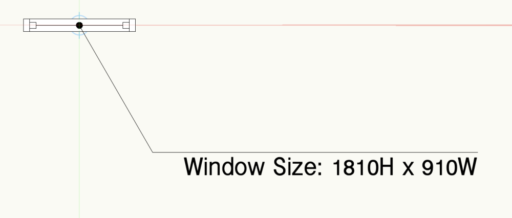
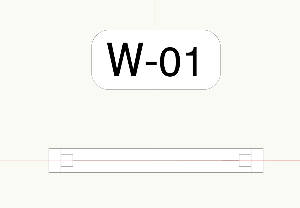
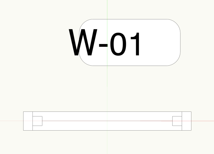
A positive offset should push the Window towards the exterior (left side) of the Wall so it depends on your Wall direction.
-
Thank you Pat I appreciate you looking at it + finding a workaround! It's strange because other tags where the text is constrained to geometry in the same way work fine i.e. a Line: and a Rectangle: So perhaps it's something peculiar about Rounded Rectangles...? We'll see what Nikolay says!

-
Have just tried to use my Window + Door ID Data Tags for the first time in VW2024 + something fishy's going on. This is how the Window tag looks normally (VW2023 file): And this is how it looks in VW2024: Exactly the same tag, exactly the same settings. Is this a bug? @Nikolay Zhelyazkov? Here are the files: Window Tag_VW2023.vwx Window Tag_VW2024.vwx
-
Just apply an offset of 20 in the OIP or Plug-in Object Options (or in the Plug-in Object Style Options if it's a styled Window + these settings are greyed-out).
-
quick landscape area question / class question.
Tom W. replied to hollister design Studio's topic in Site Design
I guess because right-clicking is how you already access the Plug-in Object Options, having an additional 'Plug-in Object Style Options...' choice here seems the most logical thing to do, but I've no objection to a button in the OIP as well: the more ways to get to these settings the better really! At the moment I right-click on the object, select 'Locate Plug-in Style in Resource Manager', right-click on the resource, select 'Plug-in Object Style Options'... That's a lot of clicking! -
Yes I remember this. You could perhaps understand if it was a single Site Model 50 miles wide centred on the IO but I think in your case it was multiple DTMs abutting each other...? So does that mean you can start drawing your geometry at the IO + build it outwards to a point 50 miles from the IO + all will be fine...? It's only if all the geometry exists outside of the 5km safe working zone that you will have problems? I've never had a model bigger than a km across so haven't had an opportunity to test this 🙂
-
quick landscape area question / class question.
Tom W. replied to hollister design Studio's topic in Site Design
See: and: -
quick landscape area question / class question.
Tom W. replied to hollister design Studio's topic in Site Design
This is common to all PIOs (+ symbols) + has been the subject of much discussion. Others have requested the same as you (assess PIO Style Options from OIP) whilst I'd be happy right-clicking on an object (in the drawing) + accessing them. @Matt Panzer said it was under consideration but not sure what the latest is... Do a search + i think there are wishlist items for this. -
I’m not saying it would be beneficial, I just meant from a practical/engineering point of view: what we could reasonably expect VW to achieve. But I have no idea how hard or easy it would be. Perhaps someone like @Matt Panzer could comment…? After all, standard walls + curtain walls are two distinct tools because they operate in completely different ways + it strikes me that we’re asking for a single tool that does both things (which might be a tall order).
-
Also, check the scale of the objects. Everything is rather large. The red circle is your 5km safe working zone around the Internal Origin. The geometry fills the screen: