
Redmodro
-
Posts
28 -
Joined
-
Last visited
2 Followers


Recent Profile Visitors
602 profile views


-
@KIT KOLLMEYER once I've seen that the tags have been disassociated then i run the reset plugins. Occasionally i have to populate the wall type IFC information to the wall types first but once this is done i reset the plugins and tags re-associate.
-
I have found that in some instances if i don't alter the tags at all but go to >tools > utilities > reset all plugins, the issue resolves itself. Be interested to see if this fixes the problem for anyone else.
-
I've also had this issue when publishing, does any think it could be due to the IFC references updating out of date information before publishing or the Pset_wall_common information from a referenced file taking priority. I have hundreds of data tags on wall types that need associating to walls every time i publish wall types plans or update other consultants IFC model references. I would be very keen to know if anyone finds a solution to this problem.
-
Tamsin Slatter (above) seems to be very knowledgeable on the subject, if you have a service select membership i would use it and contact her or the VWX technical team, as beyond what I've shown you it would just be trail and error. I couldn't get to grids with the georeferencing element as we didn't have an accurate georeferenced picture or site plan and or known station points to cross reference but if you do i thought that they self align to those points.
-
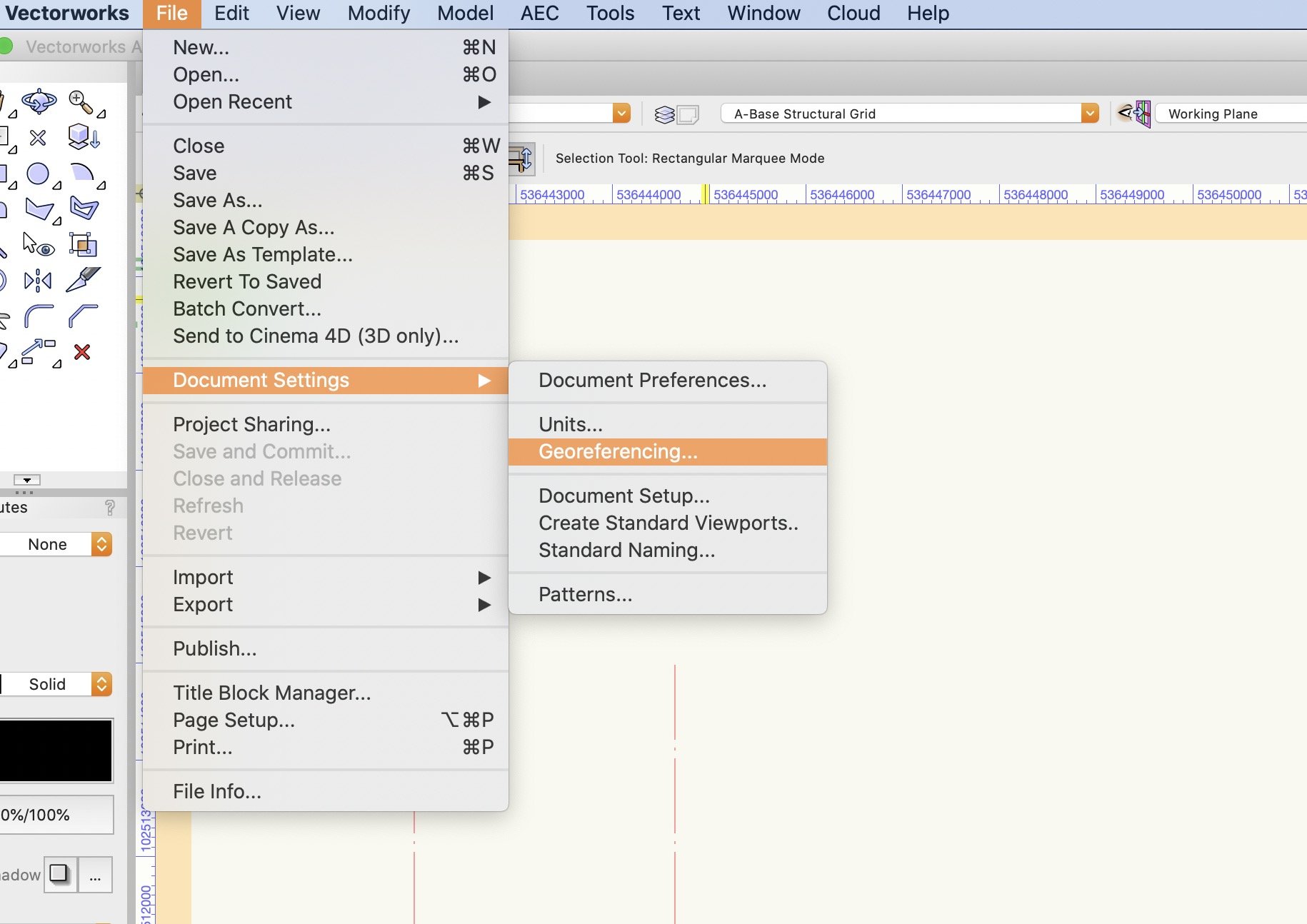
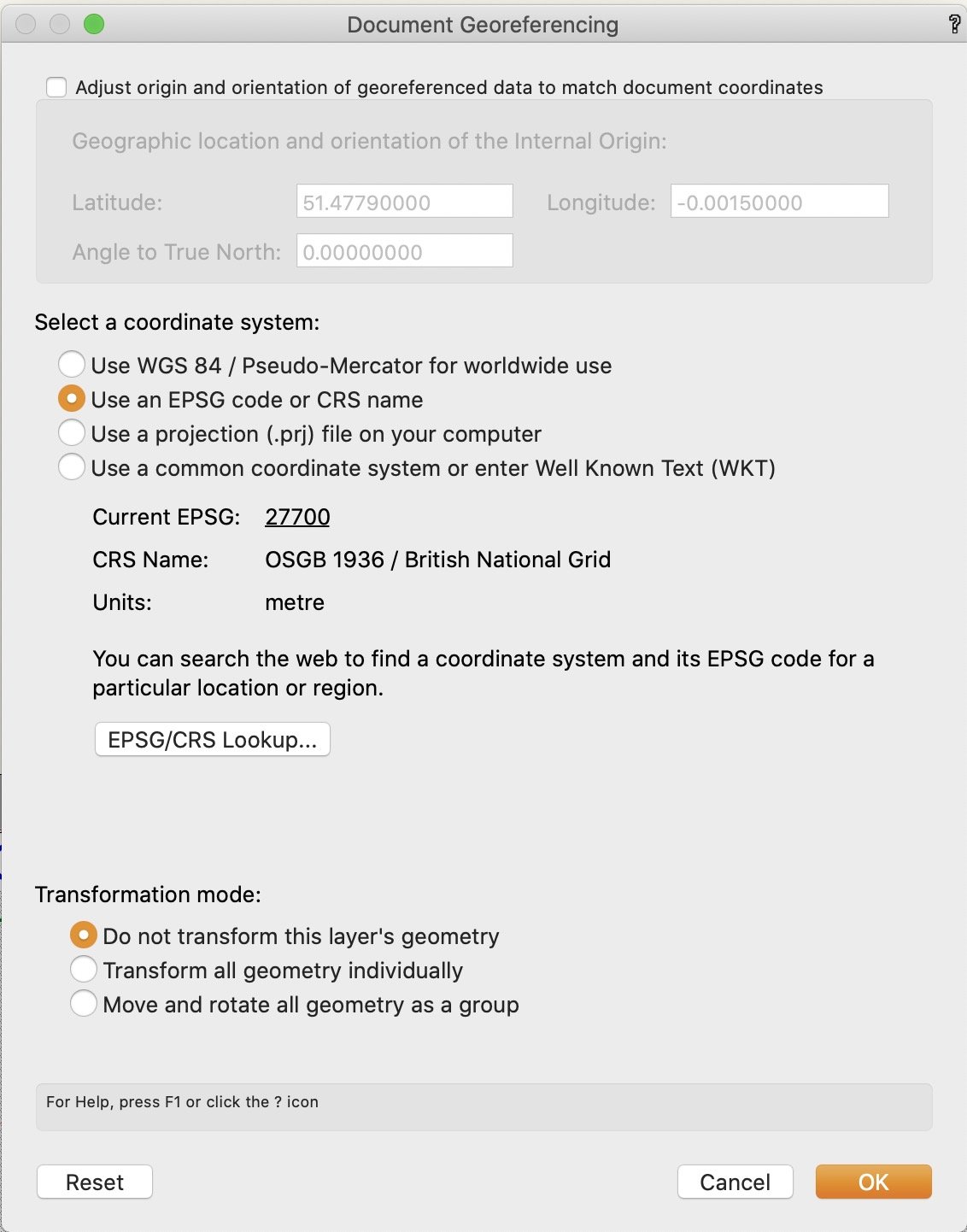
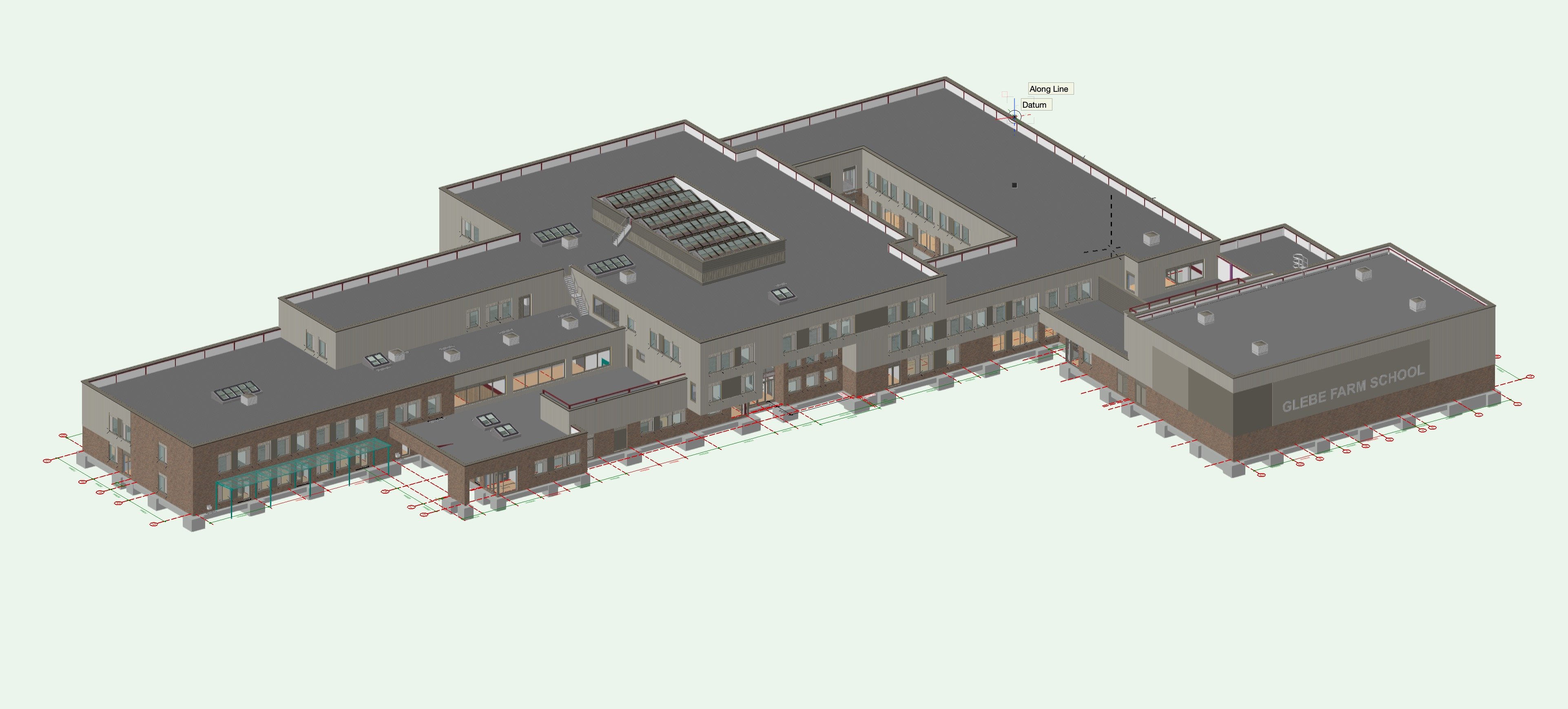
Personally I haven't needed to use geo located information, but it may have something to do with the document georeferencing settings. I think when i played around with these i could set the geo ref co-ords to match the E/N points. Its the first check box. I didn't use geo referencing as i wanted the drawing origin to be the same as the internal origin to avoid drawing glitches which were caused by the objects being so far from the internal origin. good luck


-
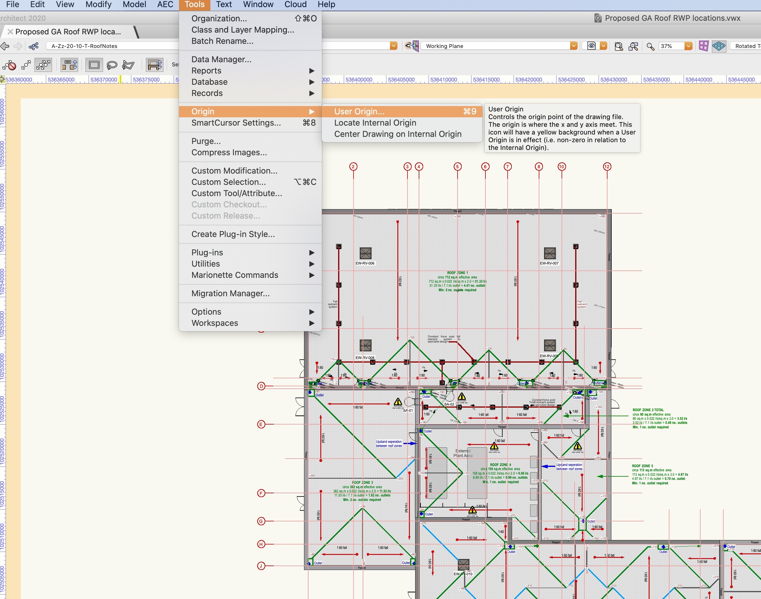
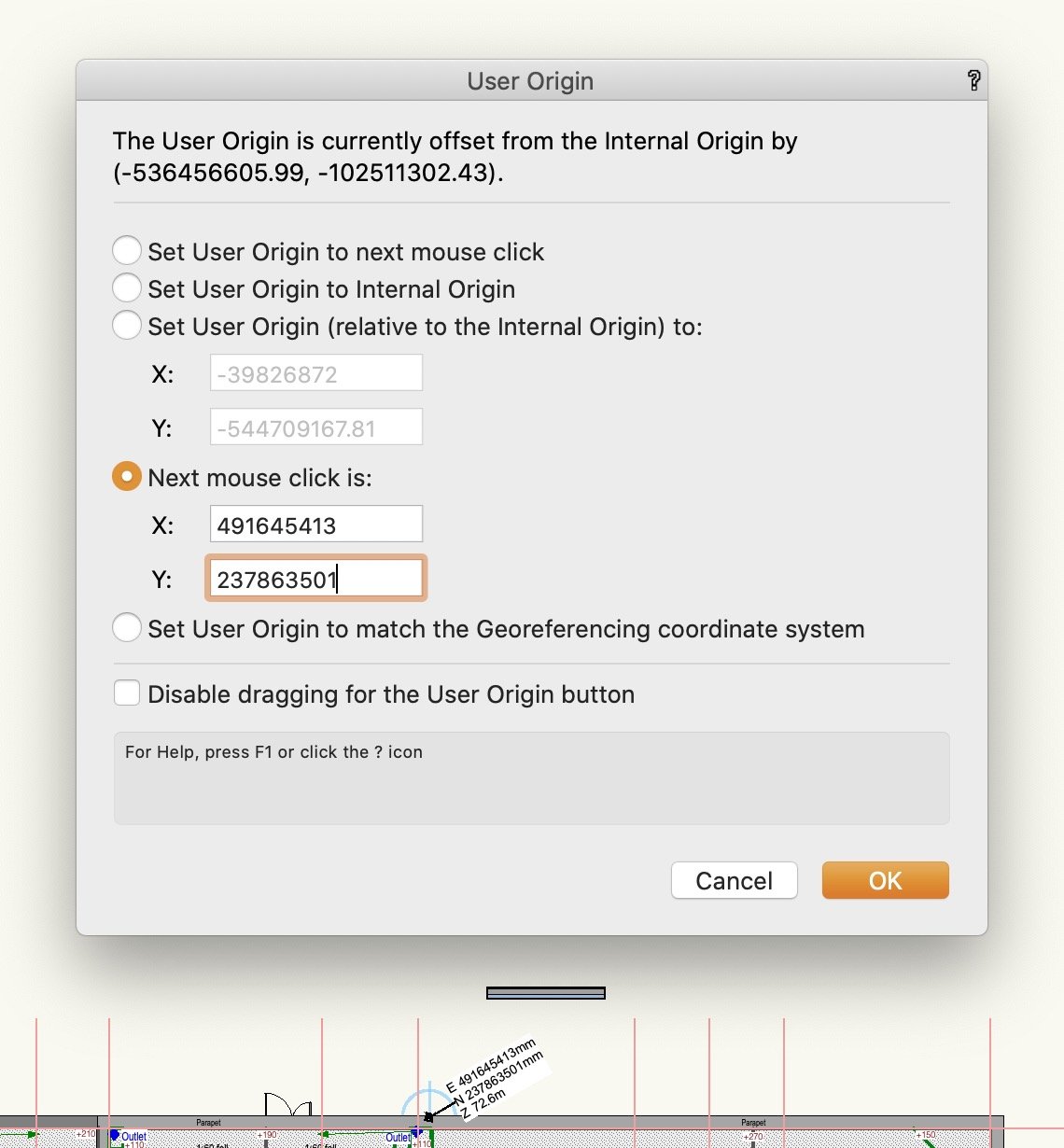
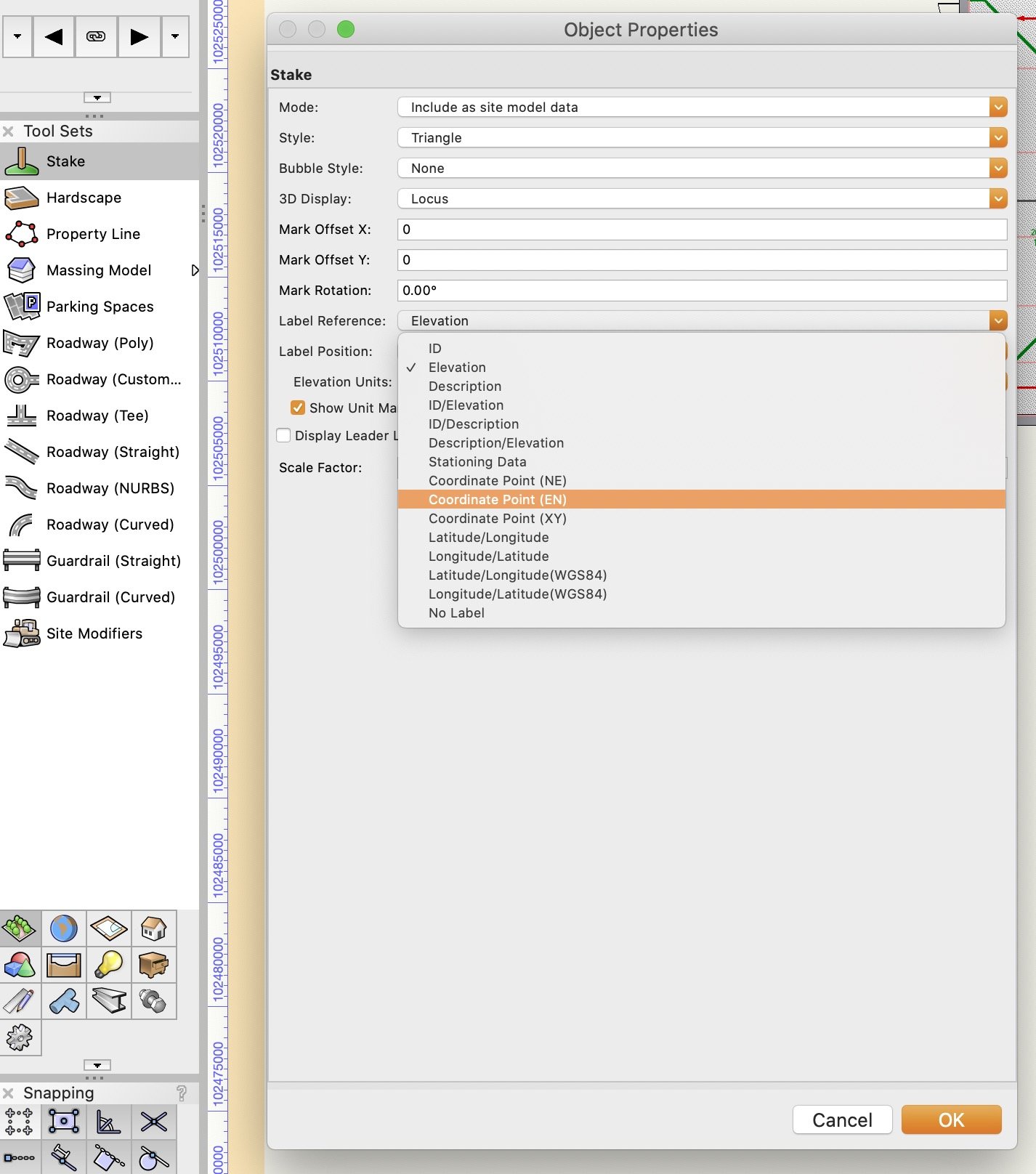
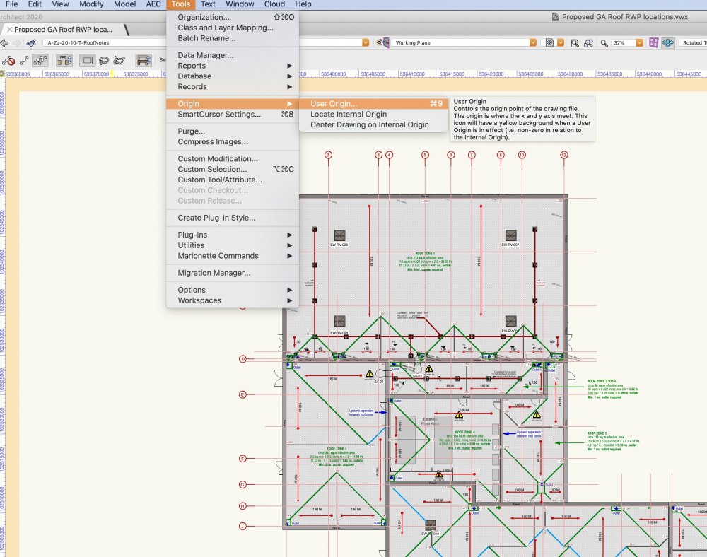
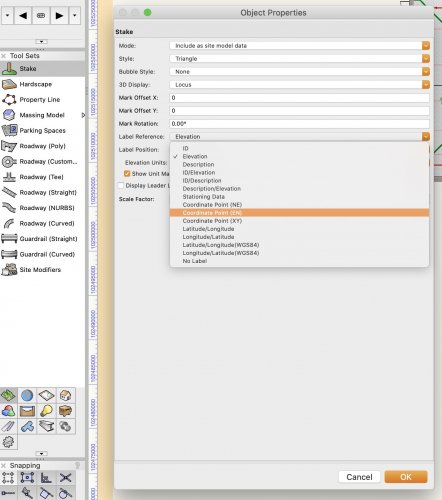
If you go to tools > origin > select next mouse click is X: (type your easting) Y: (type your northing) then go back to plan and carefully click on the point you require. You may need to set your stake tool settings over to Northing and easting if set to XY.

-
IFC export of a 16 story building takes over 45mins
Redmodro replied to ptoner's question in Troubleshooting
Any development on this ? I'm 7 hours into importing a 100mb IFC file from the mechanical engineer. -
Section viewport INCREDIBLY SLOW 2020 WHY!? Beyond cut plane
Redmodro replied to zoeageorg's question in Troubleshooting
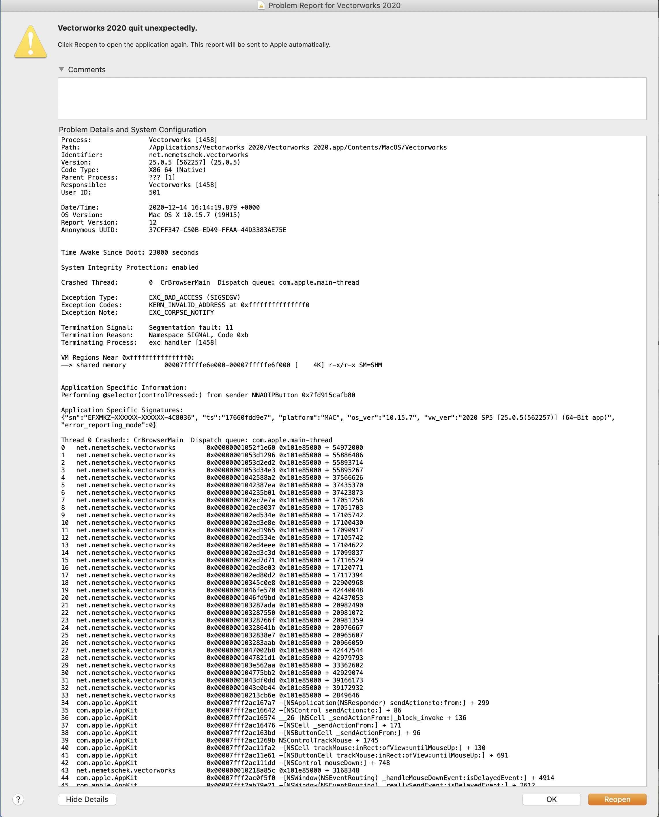
Yes I have contacted Tech support, with numerous issues. I've not heard back from them in few weeks. Apologies if i have been critical of the software, Im not trying to be derogatory or rude. TomWhitelight i have just been experimenting with modify>convert a copy to lines which while rudimentary will have to suffice, thanks for your input. -
Section viewport INCREDIBLY SLOW 2020 WHY!? Beyond cut plane
Redmodro replied to zoeageorg's question in Troubleshooting
7 secs is amazing, this is what i just got
-
Section viewport INCREDIBLY SLOW 2020 WHY!? Beyond cut plane
Redmodro replied to zoeageorg's question in Troubleshooting
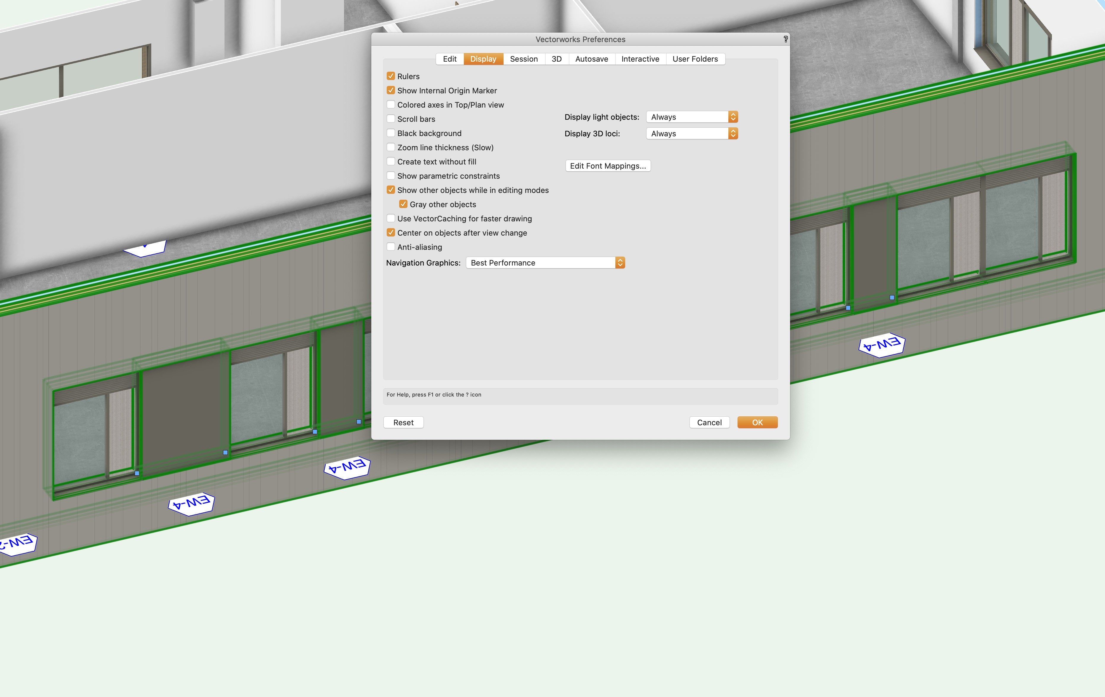
Navigation graphics set to best performance.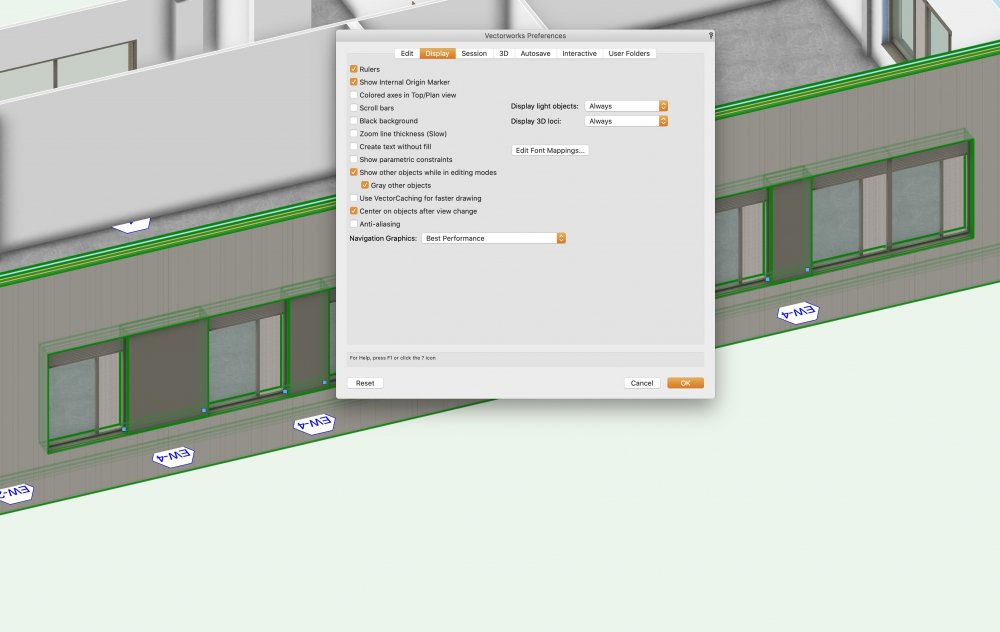
-
Section viewport INCREDIBLY SLOW 2020 WHY!? Beyond cut plane
Redmodro replied to zoeageorg's question in Troubleshooting
Thanks for trying Tom & Hamilton/black, but we couldn't even get close to setting the 3d conversion rate to High as the IFC export to the other consultants is over 1GB and falls outside the parameters set in the BEP of IFC files sizes being below 250mb per IFC model. Resolution again cant be set above 72dpi or the section view port wont generate at all. Generally 3d symbols are extruded solids and IFC data attached to them or used as custom symbol geometry within parametric window / door objects. We only use a very limited palette of textures and only in a few select locations on the facade, We have no intention of using vectorworks as a commercial rendering tool there are better tools out there. We simply want a hidden line section that we can add detail to in the annotation layer. We are finding that even the most basic section isn't possible even to check floor to floor heights. We have tried section clip and can navigate with this way but as soon as we try to create a viewport of this the software crashes or freezes for hours with spinning balloon of death. It strikes us that vectorworks is just not suitable for large scale BIM projects and should remain a tool of the domestic architect. We have resigned ourselves to manually drawing all sections at all levels of detail, we're just disappointed with the reality of what is possible. -
Section viewport INCREDIBLY SLOW 2020 WHY!? Beyond cut plane
Redmodro replied to zoeageorg's question in Troubleshooting
To create a section viewport that can be used to create a 1:50 level of detail section what are the optimal settings? -
Did you get any further with this ?
-
The files are quite large, is there an email address i can send the we transfer link to?
-
I have been experiencing similar results when publishing a drawing that has referenced drawing with data tags. If i select update out of date view ports when publishing PDFs of the drawings, the data within the data tags is lost, also the data tags in the original drawing are wiped out and display as blank and then have to manually be re associated with the objects they were attached to. It has wasted any time saved in automatically updating the data tags. Would love to know if you find a solution.