


EJ Berendsen
-
Posts
23 -
Joined
-
Last visited
Content Type
Profiles
Forums
Events
Articles
Marionette
Store
Posts posted by EJ Berendsen
-
-
Hello Jesse,
The GDTF file is created (I think) during the export to MVR. I never have imported GDTF files in this file.
The name of the gdtf file is: Custom@Chauvet Color Strike M.gdtf
And comes in the file after I have it imported in an empty file.
When I open this GDTF file thru Vectorworks in the GDTF builder I see that it had 96 channels instead of the 97 channels.
If I set the GDTF fixture mode to None the dmx footprint is 97. When I Set it the Custom@Chauvet Color Strike M. It's getting 96 channels foot print.
I have attached the Vectorworks file.
Kind Regards,
Erik-Jan Berendsen
-
When exporting a lightrig to mvr, the gdtf data that get created has the wrong dmx foot print.
I have created an empty file with an Chauvet Color strike M. Set the fixture mode to 97 channel mode.
Export the file as MVR. When importing the same mvr in a new drawing or an other program the gdtf data count 96 channels.
Also opening the gdtf in the gdtf editor shows 96 channels.
This is happening with different fixture types.
Working 2023 SP3.
Kind Regards,
Erik-Jan Berendsen
-
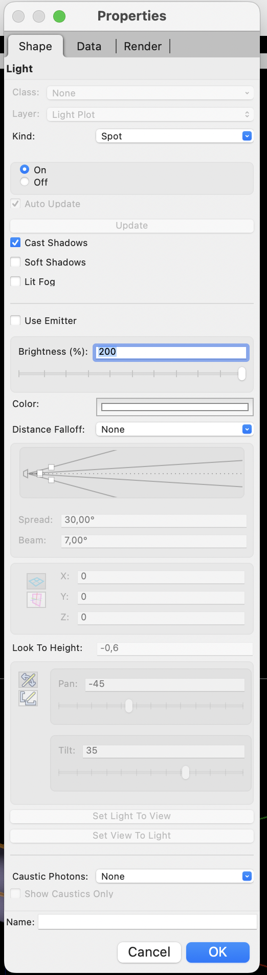
Hello Mark,
Thank you this was the problem.
With "Lit Fog" Off this works. With "Lit Fog" On, it's not working anymore.
Thanks for your help!
Kind Regards,
Erik-Jan Berendsen
-
 1
1
-
-
Hello Mark,
I have turned it on the shaded Options of the Texture. And in the Light Options.
And it is working in the Fast render works. I believe when it was off it would not show the correct behaviour in the Fast render view.....
Kind Regards,
Erik-Jan Berendsen
-
Hello Mark,
Thanks for your reply.
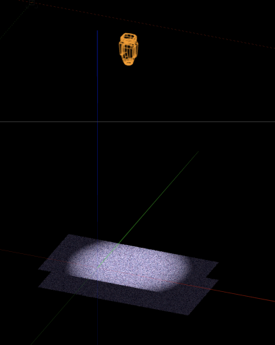
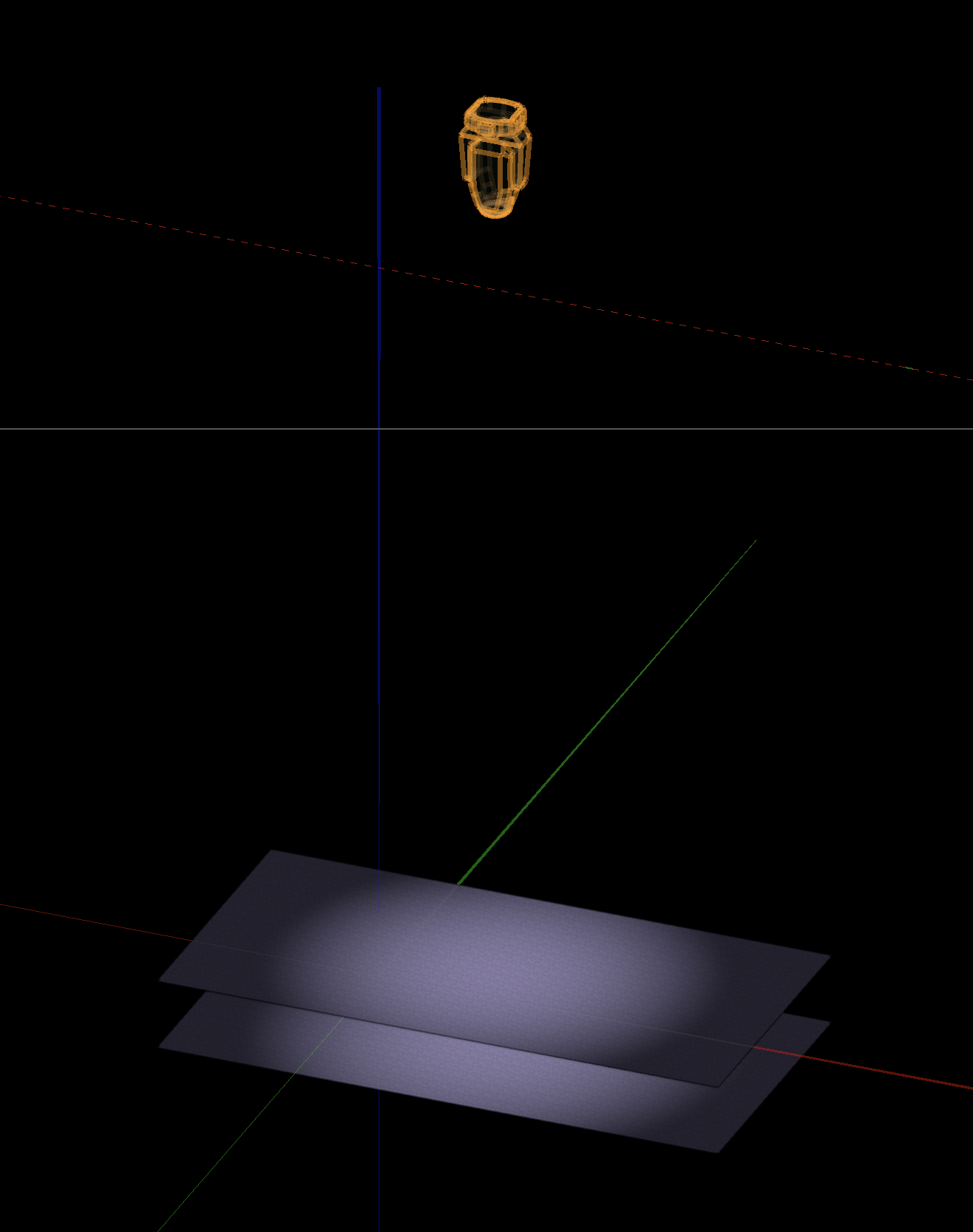
Its not only the fog that will be lit behind the floor/walls. I have drawn 2 squares above each other with a fixture on top of that. In shaded view you will see the beam hitting both squares.
I have attached two screenshot one shaded view and one Fast Renderworks.
Kind Regards,
Erik-Jan Berendsen

-
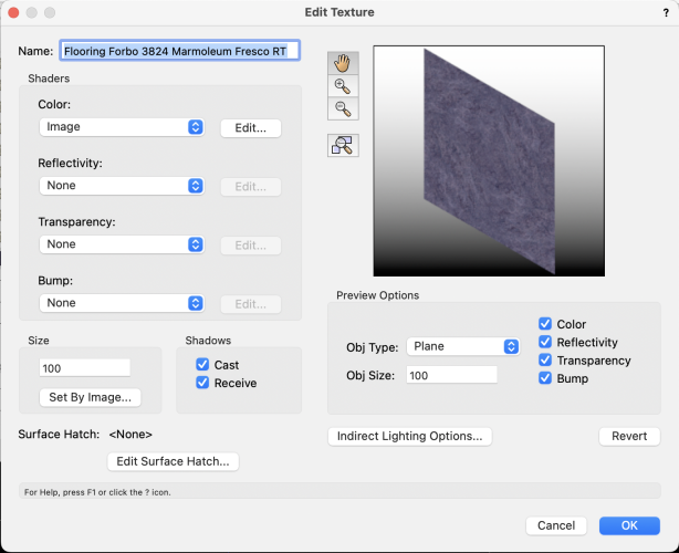
When I create a floor with an 3d Polygon applied with a texture the beams of my fixtures are going thru the floor/walls when Iam in shaded mode.
In Fast renderworks or quality renderworks the beams will be stopped by the floor/walls.
In my textures I have checked cast/recieve shadows.
Iam using a JB Lighting fixture in my test drawing but it happens with all fixtures.
MacBook Pro 16" M1
macOS Monterey 12.6.3
Vectorworks 2023 SP3
Kind Regards,
Erik-Jan Berendsen
-
Iam seeing problems with importing an MVR that comes from WYSIWYG R48/49. Vectorworks will stop responding after a while, when I have selected import geometry and data. When select geometry only its done quite fast. But it's not importing all the trussing it looks like that it refuse to import the prolyte S36R trusses. And all the fixtures are boxes, with the correct instrument data so I only have to replace them. (why can't we set the correct lighting devices in the import MVR menu, as other programs do.......)
I'm working with Vectorworks 2022 SP4, on a Macbook M1 Max.
Kind Regards,
Erik-Jan Berendsen
-
1
-
-
2 minutes ago, markdd said:
This sounds like a bug. Unless I am very much mistaken, Label Legends are not meant to respond to data Visualisation at all.
That is what I thought as well. Do I need to mention this in an other (like Bug thread)?
Kind Regards,
Erik-Jan Berendsen
-
Iam using in spotlight, label manager for channel number, patch info and purpose. For paperwork I use Data visualisation for color fill the the fixtures per instrument type.
In my viewports the different labels keeps there background color (in my case White) as set in the the label manager. But when I export my sheet layers to pdf the backgrounds of my labels are getting the same color as the instruments. This is what I don't want, I want to keep the background of my label white. Is this a bug...
Using Vectorworks 2022, SP4
Kind Regards,
Erik-Jan Berendsen
-
Hello
Trying to create a worksheet in Vectorworks 2021 as a patch sheet.
All fixtures are showing up with the correct data, except for the scrollers that are attached to my par64 fixtures. They don't show up at all.
I have added the scrollers with the "add Accessory tool"
Anybody els seeing this?
Kind Regards,
EJBerendsen
-
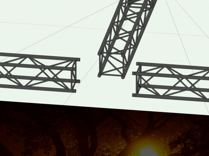
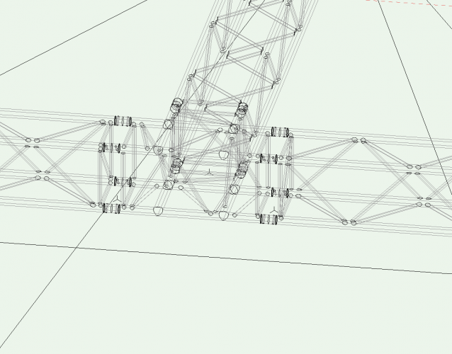
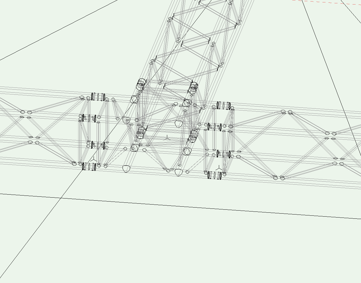
Hello,
It look like that some of the Prolyte truss symbols not getting rendered in OpenGL. You can see the symbols in Wireframe, the are not visible in OpenGL. You can select them in OpenGL (orange wireframe is visible). Screenshot added...
In fast render or final quality render the truss will be visible.
I have seen it happening now on these two symbols:
Prolyte H40V-C017
Prolyte H40V-C020
I have tried to edit the symbols but everything looks fine as far as I can see.
Iam working in 2021. Anybody els seeing this?
Kind Regards,
EJBerendsen
-
Hello Mark,
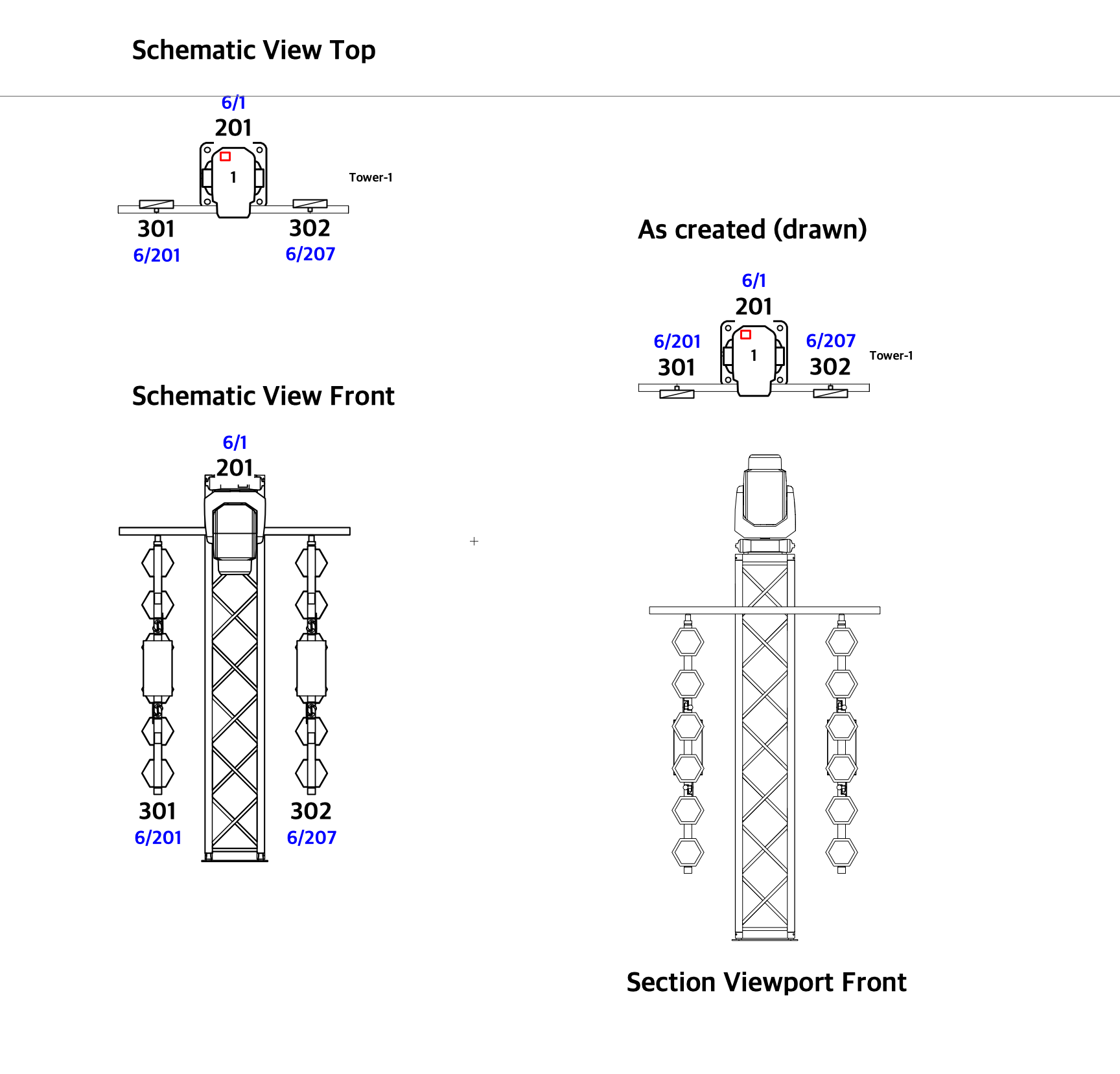
For the moving light on the top of the truss I can rotate the fixture by 180 degrees. But I can't for the Portmann fixtures. If I rotate them by 180 degree in the top schematic view, they are also rotated 180 degrees in the front view. It looks like that the rotation of them are linked on all the views of the schematic view (top, Front, Back etc ect.)
I have looked at the rear view but then the rigged pipe that's on the truss is rendered behind the truss... Not a big deal but that's not the correct info for the people who have to build it.....
For now I have rotate the 2d/3d symbols of the lighting device (postman) by 180 degrees in top view. Now I don't have to change the z as rotation, and the can stay at 0 for me. And that is the solution for my problem.
I hope that they will come with a solution for this and I really hope that we can place the fixture labels where we want them in the schematic view. As we can't move them now at all. Maybe we need an 2d/3d and schematic option for the labels in the label manager - edit field window.
Thank for your help!!
-
Hello Mark,
Here an quick screenshot. As you see all the rotations i have made on the fixtures are ignored by the schematic view.
I can rotate the movinglight in the schematic view so that it stands on the truss but I can't do this with the portman fixtures.
Hope the screenshot are clear for you.
Thanks for looking at this.

-
Schematic view question:
I have created an Truss tower with an extra lighting pipe. These together are converted as one hanging position. On this pipe a have hung to Portmann P2 fixtures.
In top/view I have rotated my postman fixtures 180 degrees, so that they are facing to the audience.
When I create a schematic view an put this in the front view, the Portmans are rendered at an rotation of 0 degrees so the back of the fixture is rendered. But the rest of the truss towers is shown correct. Also the labels of the portman are correct.
Can somebody tell me what's going on?
Thanks in advance.
-
Hello Scott,
It was a file related issue. When I created an new viewport on the same sheet layer the Legend was not visible. After I had deleted my sheet layer and created a new one
the legend was visible, and i could deleted and adding it back as you said.
Thanks for your help.
-
1
-
-
EDIT: It looks like a file problem. I have tried it in a new file and it works as it should. But the file I'm working on is still not showing
the data visualisation legend.
@ScottLebsackThank you for the replay.
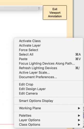
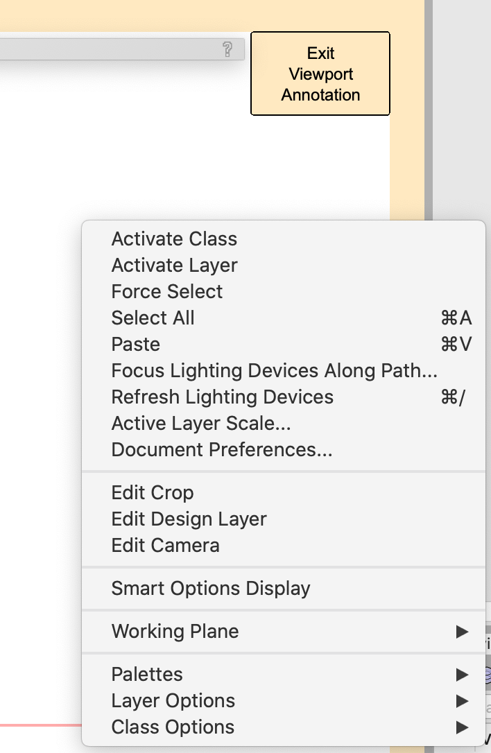
I have tried what you are saying but I don't see the "Create Data Visualisation Legend" in the right click menu.
I have made a screenshot of the menu when doing right click inside the annotation layer.
I'm using Vectorworks 2021 Design (Spotlight)
Thanks,
EJBerendsen
-
Thanks Mark,
The workflow with a groups works for me at the moment. It would be great if we can handle pan tilt per cell in the future........
EJBerendsen
-
For what ever reason i don't get a Data Visualisation Legend at all.
I have made 3 different types and none of them adds a Legend in the viewport as described......
Is there a setting what i don't see.....
EJBerendsen
-
Thank you Sebastiaan for the link.
I have followed the workflow. But without any luck.
I have created a pipe with 6 par cans (no lightning devices). Select everything and create a group. It's acting like a multi cell fixture for the fields Color, Patch, Channel. But I can not focus each par to an other focus point. So if I set par 1 at focus point A, then all the others go to focus point A. When I set par 2 at focus point B, then all the others go to focus pont B. I have tried to make 6 different Par64 symbols for the nested symbols, by duplicate them and give them other names Par64_1, Par64_2 ect ect. Maybe I oversee something but it worked on previous builds of Vectorworks......... when you followed the earlier video of Mark.
Hope somebody has a solution for this.
-
I'm trying to make a 6 bar as done in the video. I can give each par64 his own channel number and patch. But I can not give each par 64 his own focus point. When I attach an focus point to one of the par's i get a red line indicating the focus direction from the centre of my 6 bar..
I'm working in 2021 can this be a bug?
-
I like to use data visualization, in spotlight, to identify the different spot types. This all
works good. Is there a way to exclude the labels of the spots? They get the same background color as the spots, I would like to see that they keep the background color as set in the label manager.
thanks,
Erik-Jan Berendsen
-
I am having the same problem, I don't see the updates at all. And the updater tells me that I am up to date........ But still working in SP2.2


Graphic legend - symbols - "count" function
in General Discussion
Posted
Would it be possible that we can set a filter for the count (or for any function/graphic legend). So that it only counts the fixtures that are on a specific layer. As we can with Instrument schedule.
Kind regards,
EJBerendsen