Todd Drucker
-
Posts
24 -
Joined
-
Last visited
Content Type
Profiles
Forums
Events
Articles
Marionette
Store
Everything posted by Todd Drucker
-
Troubleshooting Wall tool VW20222
Todd Drucker replied to Todd Drucker's question in Troubleshooting
@Matt Panzer, Thank you for the response and happy Friday. I can share the latest file via WeTransfer if you send us an email to show you how the walls are reading on our end. When we export them, the IFC is correct, just not on our screen. And it isn't every wall, but most. Sarah described it as pancaking. We're not sure exactly what causes it, but if one person fixes it, it will reappear after a few save and commits. Our workaround to copy and paste walls works, just isn't permanent and takes time away from our production. On the bright side, it doesn't affect our plan workflow, but the walls are not showing up on section viewports, nor clip cube. The classes are on and objects in the wall (i.e. doors) are generating, just the walls are pancaking to the z-0. TD -
Troubleshooting Wall tool VW20222
Todd Drucker replied to Todd Drucker's question in Troubleshooting
@Matt Panzer, Thanks for getting back. Our temporary fix is to change any parameter (cut and paste / move 0,0,0 / change bounds will all regenerate the walls properly), however, this fix usually gets override when the next user S&C. Would sharing the file help? You may email me **@gkvarchitects.com. Feel free to send a PM or have Sarah Barrett provide GKV's BIM team's contacts. We last discussed this with her via email in Mid December, but never were able to resolve this. -
Troubleshooting Wall tool VW20222
Todd Drucker replied to Todd Drucker's question in Troubleshooting
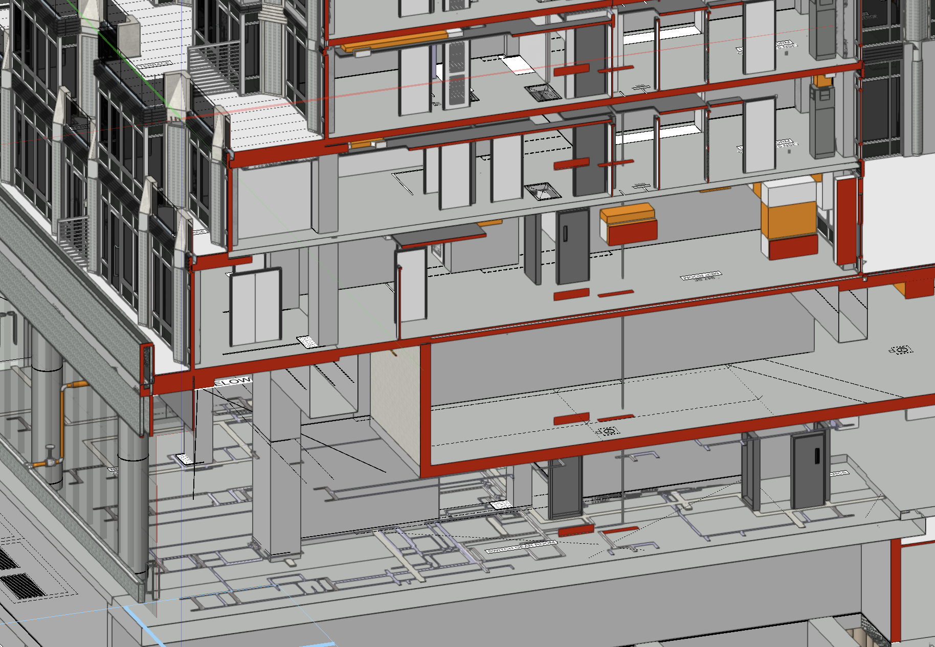
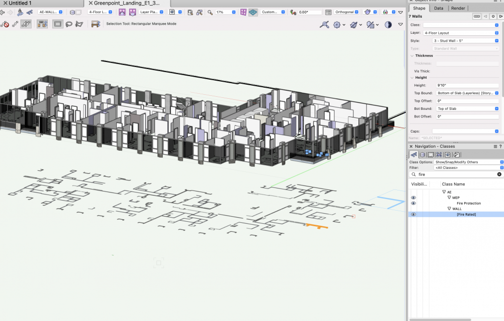
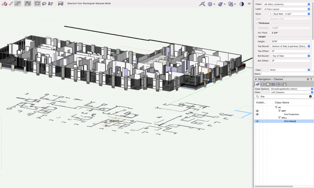
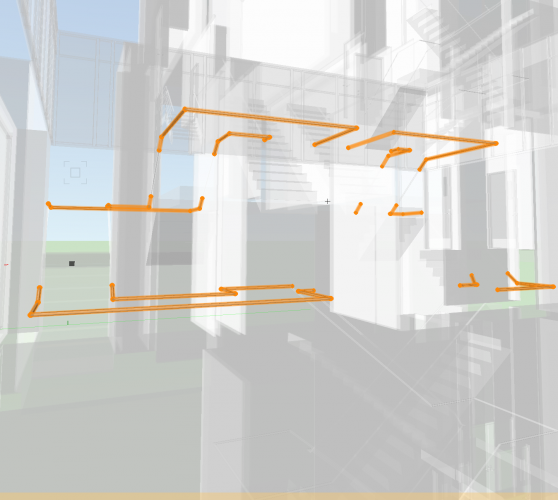
@Matt Panzer Hey Matt, We're producing sections and this is still a nuisance. We modified the walls and they still revert back to this flattened state. We've tried copy and pasting and moving to 0,0,0. We notice that any modification will regenerate the walls to correct location, but after S&C, the problem reappears. Our walls export properly to our consultants with IFCm, but our model still flattens everything. Doors in walls are in their respective location relative to the story, but the walls themselves are flattened. The corresponding section from the clip cube attached shows the doors, but not the walls, with all layers turned on. Any other ideas how to fix this?
-
Looking for tutorials and template for Data Visualization
Todd Drucker replied to Matt Hall's topic in General Discussion
@Matt Hall, slightly outdated, but this is a good overview. https://fliphtml5.com/kgve/bpml/basic -
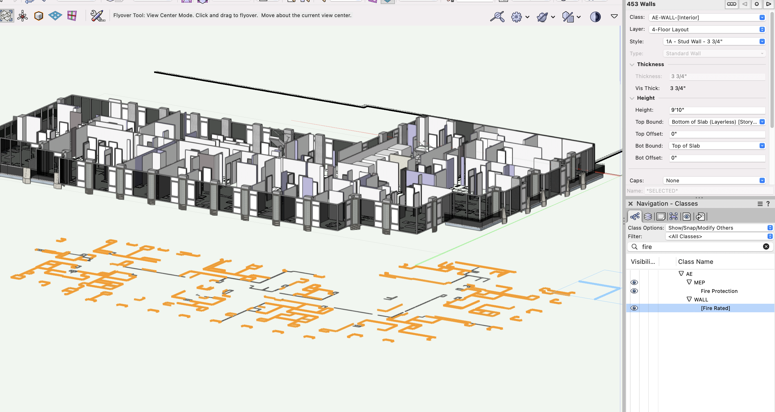
@sbarrett @Matt Panzer , Has this been picked up in the latest SP of VWX 2022 . We're having trouble finding this on the forum. We have had success in plan, but not section. In plan, we used this for Fire walls and dashing elements for RCP/PTE (furniture, fixture, appliances). The structural engineer sent us slabs and we would like to override the slab class with concrete hatch where we cut through it. We can override the clip cub to turn everything to concrete, but don't want to override other elements such as walls, windows, etc. Thank you again. Your team is allowing us to advance more and more each day. TD
-
Troubleshooting Wall tool VW20222
Todd Drucker replied to Todd Drucker's question in Troubleshooting
@Matt Panzer, nice to meet you. @sbarrett has helped us tremendously over the past 2 years. We started this model in June 2021. I believe we upgrades to VWX 2022 early on as recommended by Sarah. It helped with a lot of our initial troubleshooting. This ultimately didn't affect our workflow as it was mainly noticed when moving around in 3D. Rather than copy and pasting, we noticed if we click the and bound and select the same field it will properly generate. From time to time it still graphically displays in the way the screenshot shows, but we learned to ignore it since it doesn't affect our coordinating ability since all 2D information and IFC transfer look proper on the other end. Kind regards, TD -
Hello, We've been using VW2022 BIM and have been happy about the newest version (thank you for the progress bar) That being said, we discovered something that's off with the wall tool. Our walls are typically bounded from TO slab to BO of slab via story heights and the 3D display of the wall is correct, however, it projects the 2D graphics to the 0-plane in the z axis. This is true on all floors. A quick fix is to copy and paste the walls, however, when we reload the project file, the same glitch occurs. We're not sure if it's an error in the setup of walls on our end, or if this is something the VWX team is aware of. Would appreciate some insight. Thanks.

-
Rhino.Inside for Vectorworks
Todd Drucker replied to elepp's question in Wishlist - Feature and Content Requests
@JuanP@sbarrett I also am interested in this feature. Very interested. Marionette is a powerful tool to control Vectorwork's function, however, everyone who has graduated architecture school in the last 10 years has had exposure to Grasshopper. At my practice, we have one license of rhino, and young employees want to use these tools to design... but the process is segmented, slow and not practical for teams working on project with different levels of experience. I would like to continue using Vectorworks for my entire professional career, however, if these functions won't be adapted into future service packs, I will convert to Revit. I have grown to love the power of Vectorworks and the collaboration it offers.... especially as a BIM tool.... and all that I request is that Vectorworks keeps working to match competition's functionality. ..... Other powerful tools are Hypar and Cove.Tool...and both of these developers are working on functionality with Vectorworks. Grasshopper does not have to exist within the Vectorworks platform as Marrionette is the tool to control workflow... however... I would really like to see Rhino.Inside cooperate with Vectorworks so designers of all ages can use tools they are comfortable with and advance digital production! https://hypar.io/workflows https://www.cove.tools/ -
This tool will change the game for quick concepts. I recommend you check it out. https://hypar.io/workflows
-
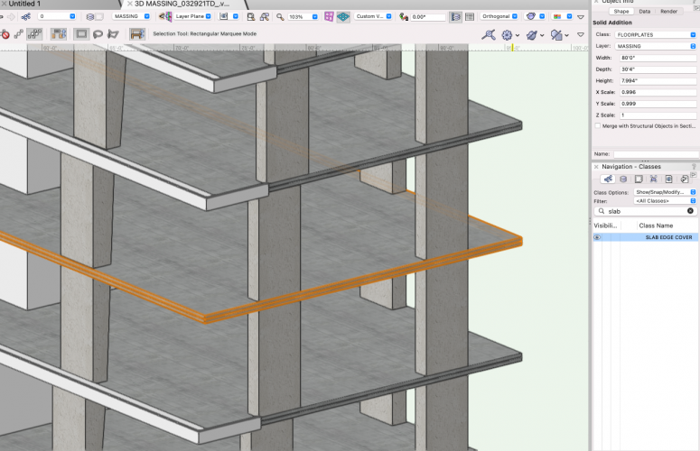
@Tom W. Appreciate it. This project had 30+ setbacks and at this point... we're pretty much wrapped up. My next challenge will be setting this up with Marionette so the same EAP can be applied to a slab of any size Your method is a lot easier because I started with the slab size we really have. In my method, I had to calculate the midpoint of the EAP profile, and subtract that from the slab's overall dimension. The next project will be smoother! I like challenges and I LOVE learning how to solve them more efficiently. Best of luck to all BIM users.
-
Thanks @Tom W. This is why I come to the forum. The Subtract 3D Object from Slab is a great command. I'll be sure to use it going forward. One question, what is EAP+?
-
@Christiaan it is just a profile on the edge of the slab. The whole object is a slab, just a negative relief on the face of the slab. In the field, the slab and the slab edge profile, would be monolithic and casted at the same time.
-
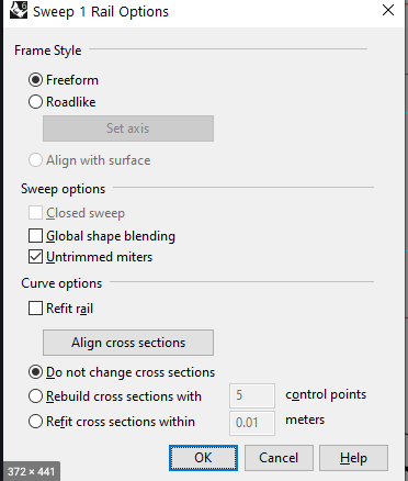
To my knowledge this function does not exist... but would like it to be a setting in future service packs. Our building has exposed slab edges and we designed reveals in the slab edge. I modeled this as a solid addition of an "extrude along a curve" and 2 NURBS surfaces (2D squares).... Took some trial and error... but was satisfied with this for LOD100. We didn't even try to get pass this, as there would be further depressions for window walls and other details not worth designing for a 3D render. Two wishes... One is for the slab tool to have a slab profile option. The other is for "Extrude around a curve" to have multiple options where the profile extrudes along the path. By default, it's centered, but would like the option to select corners and midpoints, similar to the align cross section options built into Rhino's "Sweep1D" tool.
-
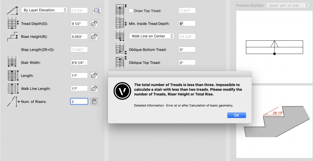
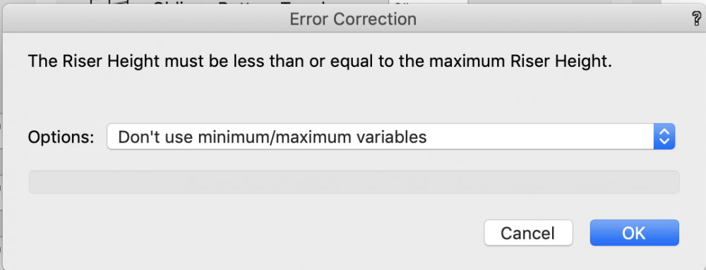
Hello world, We have a split level in our project and would like to model a stair with 2 risers and one landing, however, the tool will not allow for that. The rise should be 7.625" with 2 risers, not 5.083" with 3 risers, but I can't override the parameters. Any easy way to override? I started another topic where we tried designing a shipladder and had the same issue, where the shipladder can have a rise up to 10". I was able to modify the Min/Max setting for that issue, but am having trouble on this stair. Best of luck
-
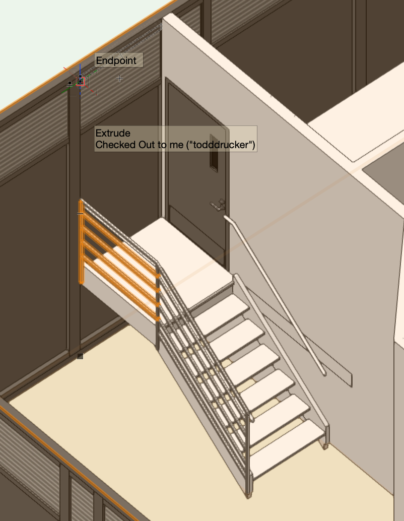
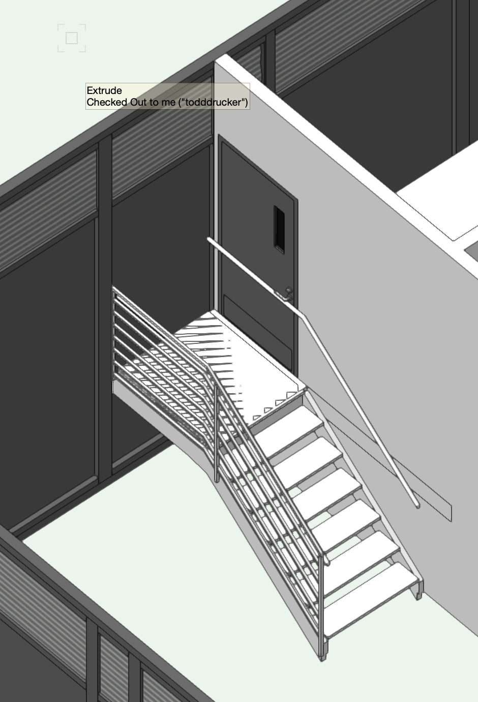
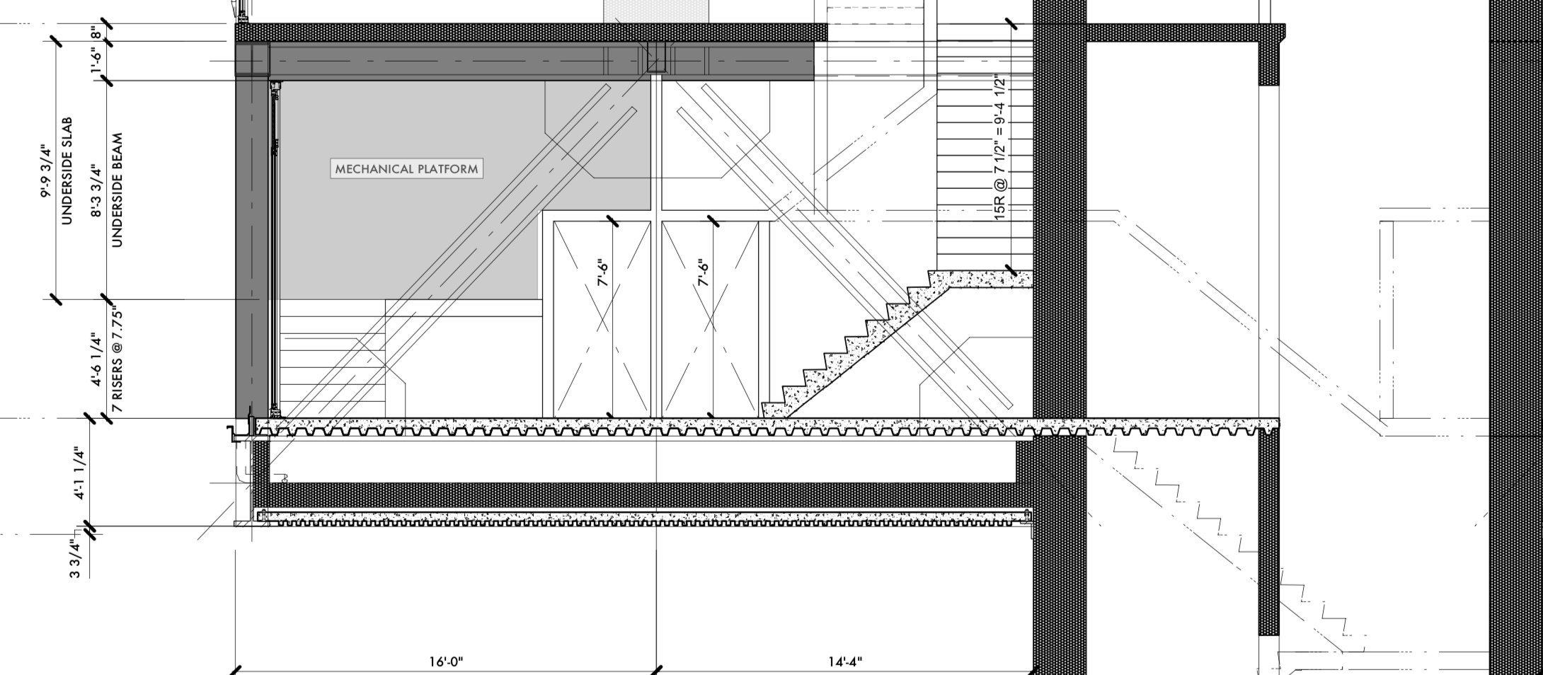
Z Offset for Door Tool & Metal Stair Troubleshooting
Todd Drucker replied to Todd Drucker's topic in Architecture
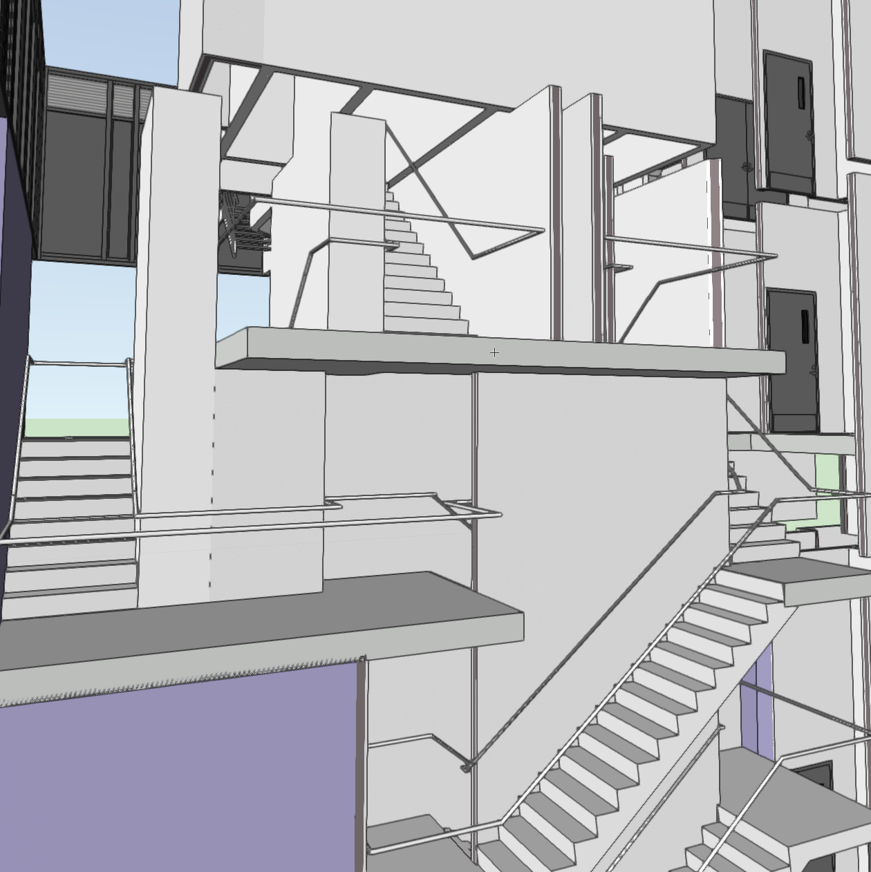
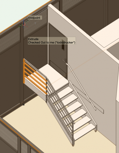
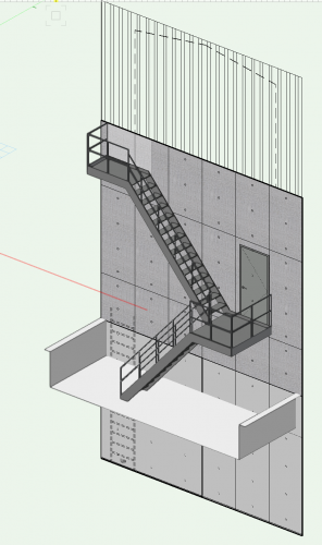
@zoomer @E|FA Appreciate the tips. The "drawing top stair" was helpful to show the railing, but it led to issues with the handrail and stringer blocking the door. The right rail extension can't be negative, and the stringer can't be defined as a right stringer and left stringer, unlike railings (which is a great feature!) I ultimately used the profile through @E|FA trick to manually draw the guardrail and I grouped it in the stair container for our BIM model. Ultimately, we got to where the model wants to be, so thank you to everyone's help. Now about railings..... We have a pretty wild stair transfer, and I ended up extruding along a curve to continue the handrail. It isn't perfect, but it was able to conveys the appropriate design intent. I included more screenshots. This is my first BIM project using Vectorworks and I love learning all these features on designing in 3D. The software is very powerful and makes mundane task, IE, stairs, simple, once the commands are well understood. Again, the forum is the best place to troubleshoot. I appreciate the help. Happy NYE everyone! From NYC, where we are a few hours from midnight. Best, Todd Drucker

-
Z Offset for Door Tool & Metal Stair Troubleshooting
Todd Drucker replied to Todd Drucker's topic in Architecture
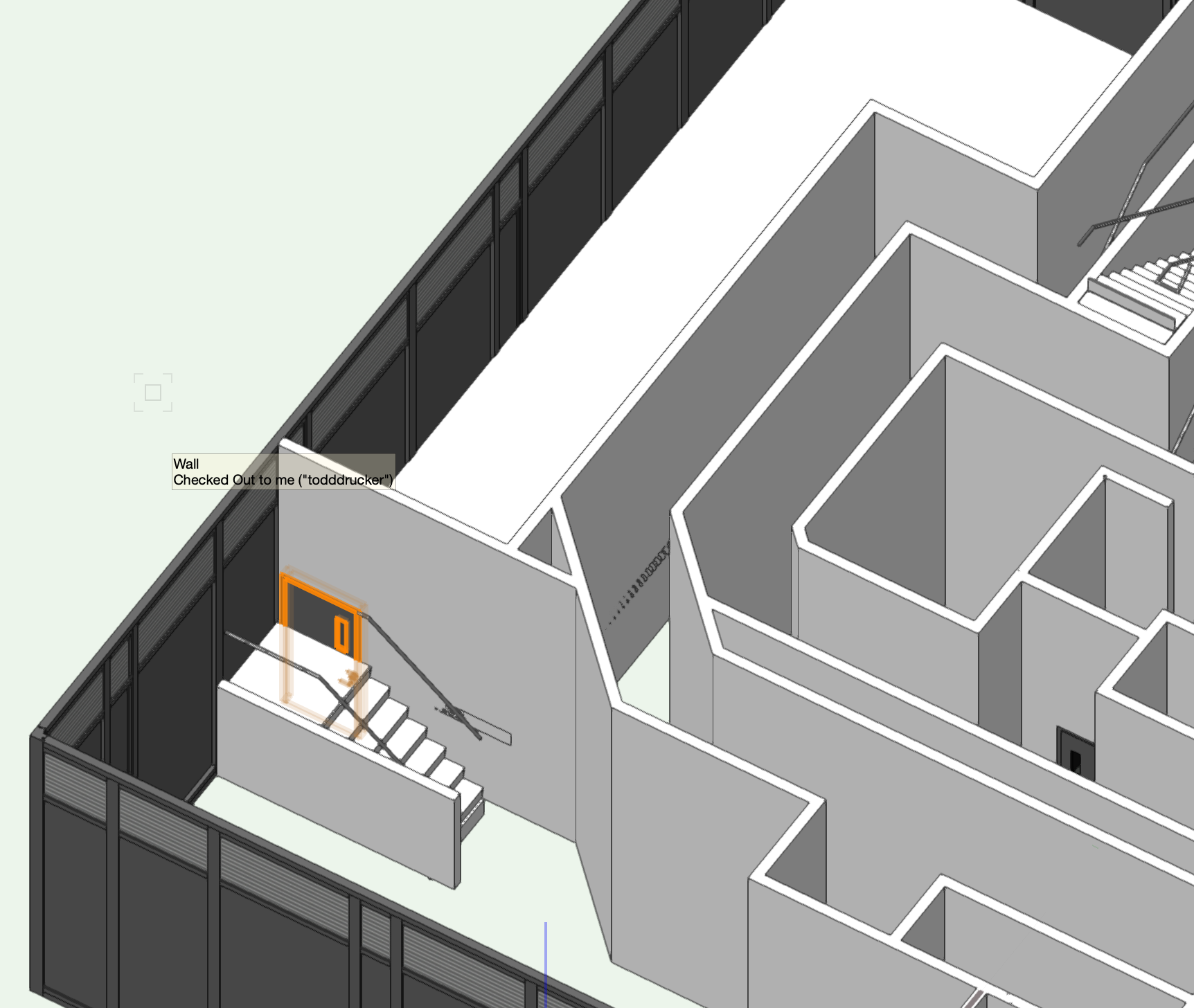
Thanks @zoomer!!!! I figured out the door in wall. It was pretty easy... all that I had to do is edit the height data field in the object info. I also modified the stair on this mechanical raised floor to be more accurate of the construction. It will be helpful to discuss this feature with the client and further design the stair to code/aesthetic preference. The only thing I'm still having trouble with is having the extended guardrail (on the left side only) have the same vertical post. I don't think the stair tool can do this because it only adds the guard rails along the stringer. @vectorworks can address this by having a Standard Configuration stair that is Straight, with a single landing at the top, and no additional stairs beyond the landing. The current Straight & Single Landing stair configuration requires 1 or more risers above the landing. Progress always feels good. Happy to be more proficient in 2021!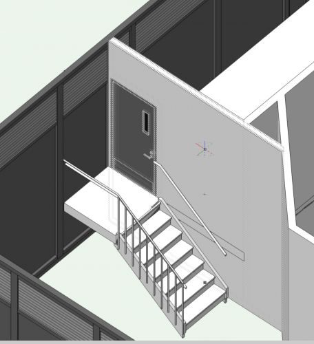
-
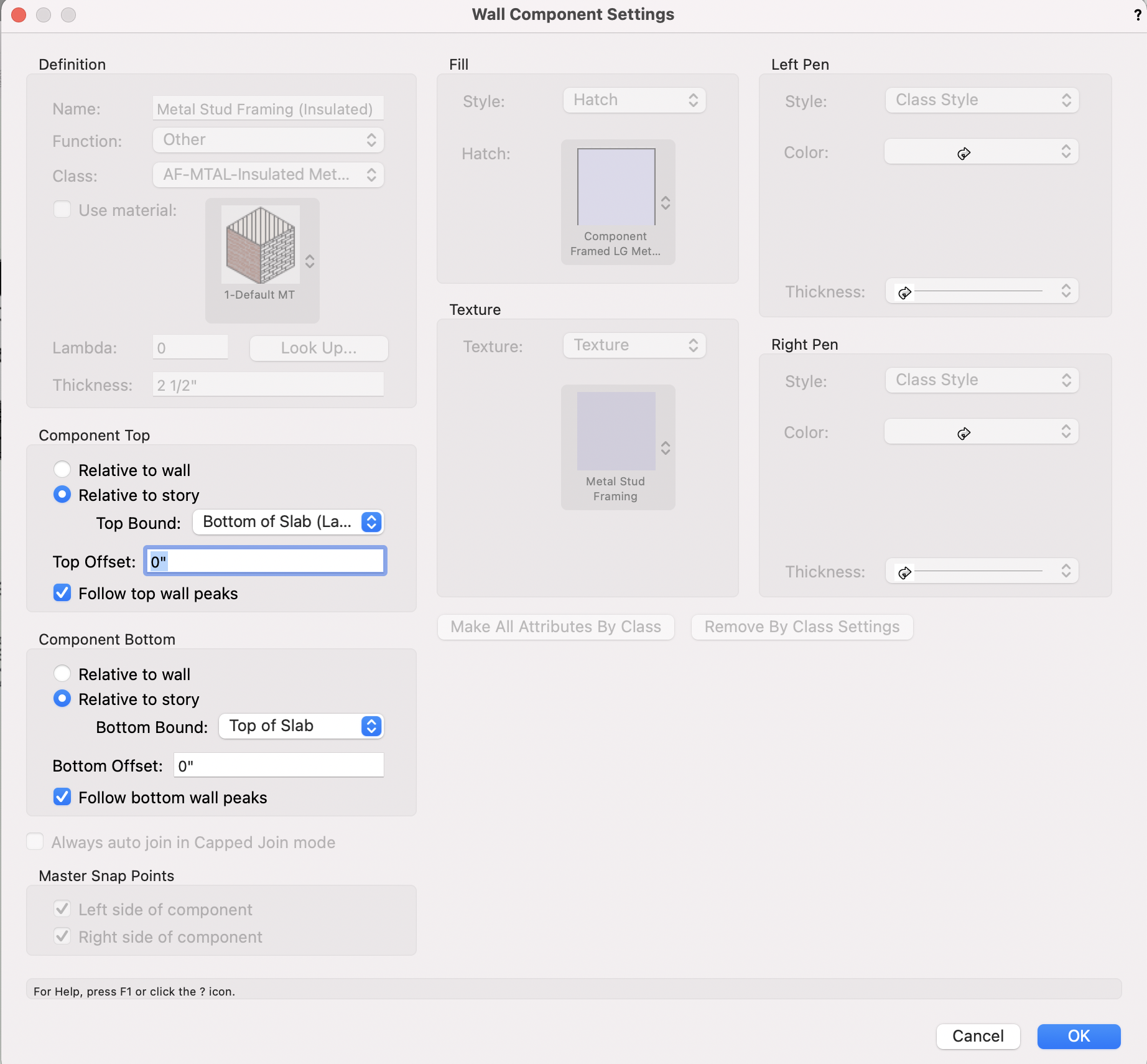
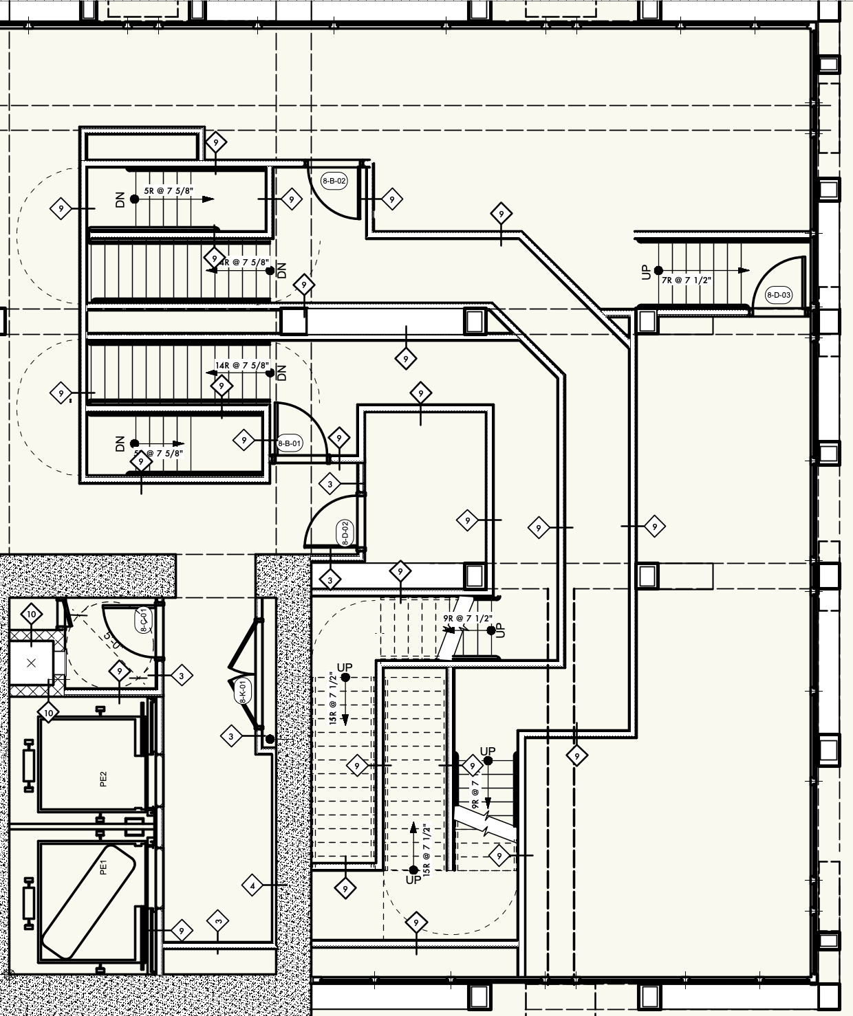
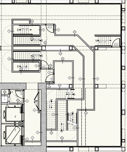
Hello world, We have a BIM project and have two troubleshooting modeling issues to review. First is a raised floor system for a mechanical room. The raised floor system isn't truly a mezzanine and we would like to know a better set up for the walls and door in wall. We want the fire rated wall to continue from the top of slab to the bottom of slab and we would like the door at the level of the raised floor system, not the top of slab for the floor. Any suggestions? We attached some screenshots of the architectural model in 3D & 2D, with the structural .ifc turned off. Furthermore, we would like to know of any development for more customization on the stair tool, specifically for metal stairs such as the one on the raised floor system and metal ship ladder stairs for bulkheads. The closest stair construction is "Outside Stringer", but we want to know how to override the max riser count. We get an error message (below) and are having trouble generating the stair. Is there a method to override the riser height to allow for 8.5" (or greater) riser heights. For the roof's ship ladder, we modeled a conventional 3D symbol for the time being, but we would prefer to use the stair tool because it would allow us for more precision on the total rise to the elevator machine room top of slab and elevator bulkhead top of slab (which are all defined in the BIM files "story" data field). See the last screenshot & the .vwx file for the shipladder stair if anyone knows how to generate this stair using the stair tool. If not, is there a method to tie a typical 3D symbol to the same story fields? Excited to see your answers. Best, Todd Drucker BULKHEADS STAIR.vwx


-
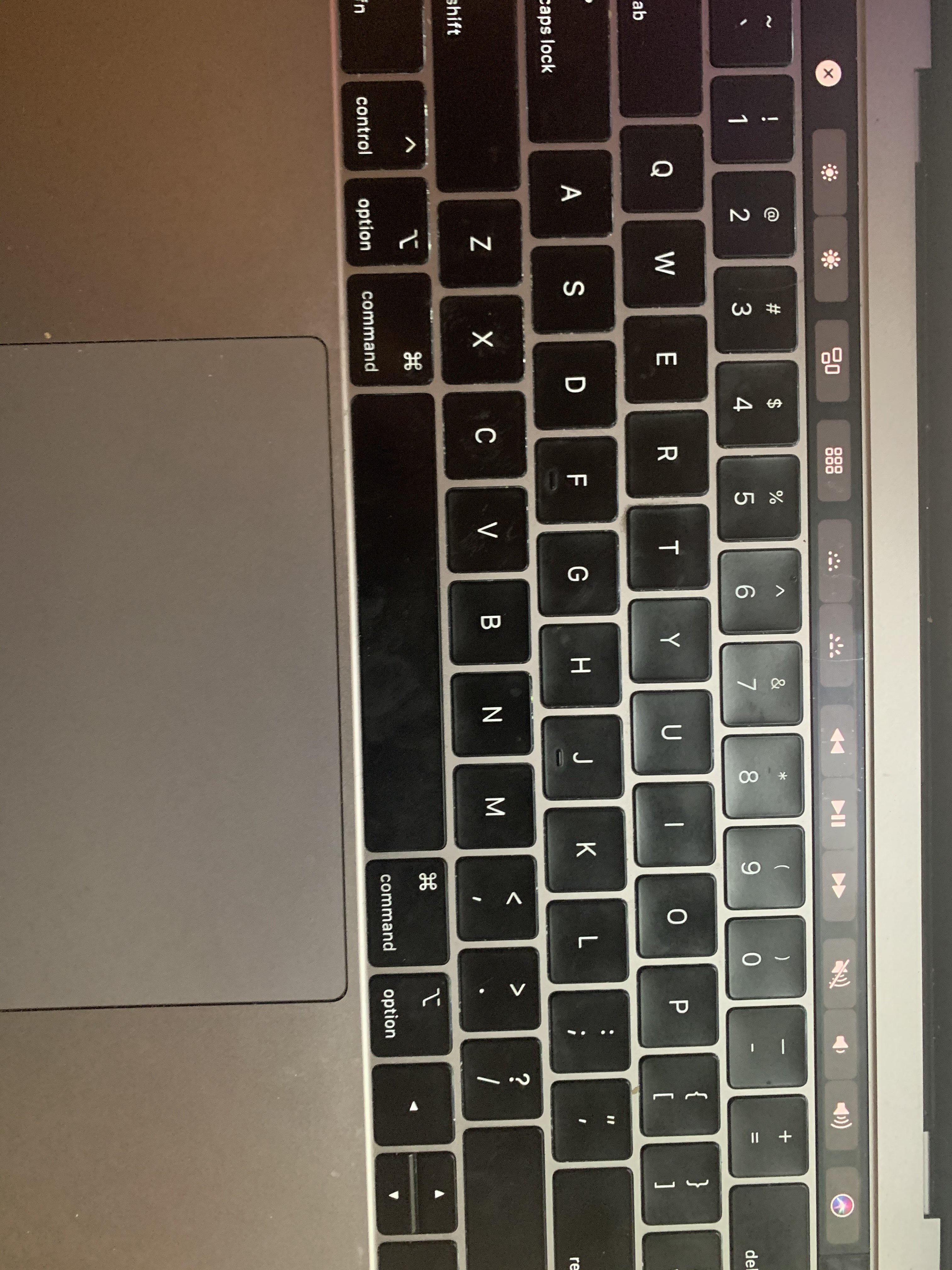
Disable 2018 Macbook Pro (and newer) Top Row Keyboard
Todd Drucker replied to Todd Drucker's question in Troubleshooting
Thank you @Andy Broomell. I was able to have the Touch Bar only display the "Expanded Control Strip" (brightness, toggle, volume, etc). Other options are App Control (my issue above), F1-F12, and customization. -
Disable 2018 Macbook Pro (and newer) Top Row Keyboard
Todd Drucker replied to Todd Drucker's question in Troubleshooting
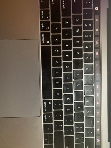
@bcd TLDR - Apple's new keyboard is not ergonomic Thank you for taking me to the workspace menu, but I don't see the top row of keyboard called out It replaced F1-F12. I included photos of what it looks like when I open Vectorworks and what it looks like when I no application selected I would like the top row to remain with simple apple functions (esc, brightness, toggle screen, volume). If these "smart" buttons were disabled, my workflow would be enhanced as I access tools with shortcuts and icons, not the smart keyboard. Thank you!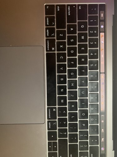
-
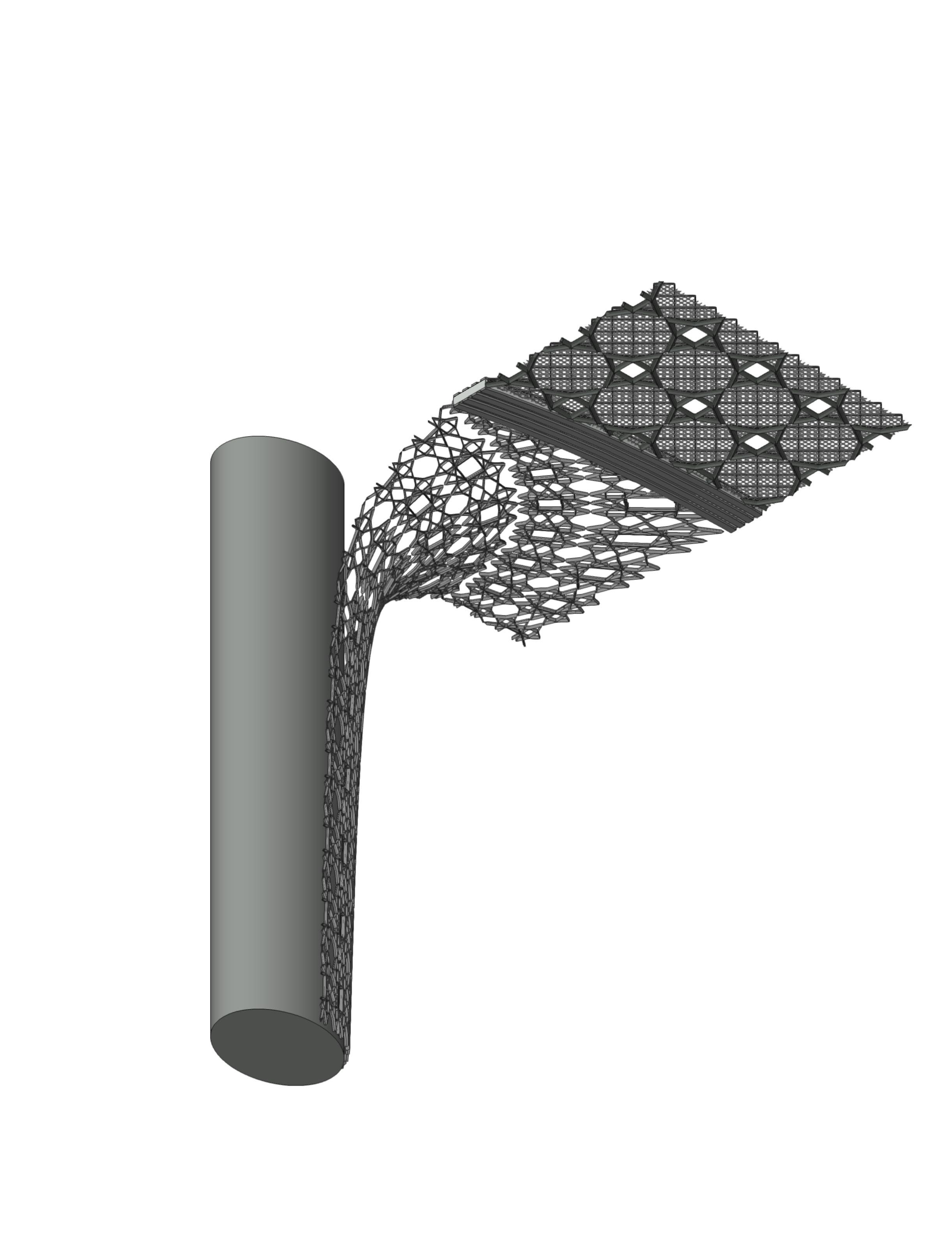
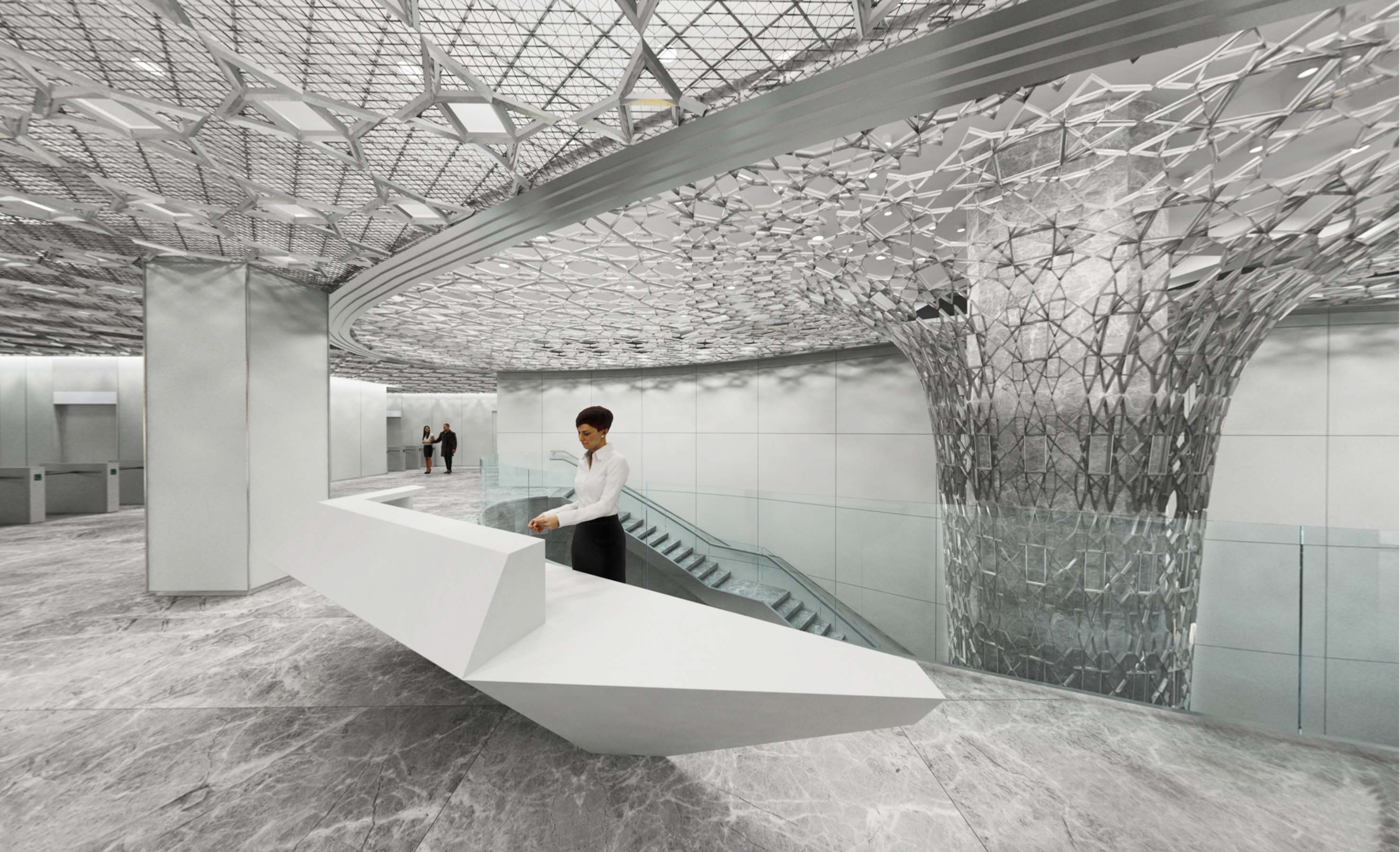
Help with understanding List on creating a Truncated Cone
Todd Drucker replied to Todd Drucker's topic in Marionette
@GRZEGORZ Thanks for your help back in April.... For this project, I moved away from Marionette and used built in tools including lofting, surface array, extrude along a path, etc. to build the model. Was happy with the end result... Now onto BIM...
-
Disable 2018 Macbook Pro (and newer) Top Row Keyboard
Todd Drucker posted a question in Troubleshooting
Hello world, Nice to be back. I've been using vectorworks for both 2D drawings, 3D modeling, and BIM for 3+ years. Is there an easy setting to disable / modify the top row of icons on the new macbook pro keyboard. Too many times I find myself tapping an object that switch my screen from 2D to orthogonal, which can slow down a machine, when drawing maps and buildings. While I sometimes find it easy to tap & scroll through functions, too many times, I touch an icon as the keys are not tactical, but touch base. Looking forward towards the communities thoughts. -
Help with understanding List on creating a Truncated Cone
Todd Drucker replied to Todd Drucker's topic in Marionette
Thank you @GRZEGORZ. This is really helpful to understand how the Vectorworks tools function. In my script, I was able to offset the curves, but didn't include the deleting and conversion to have control over what is being lofted. I am trying to modify the math so the series is exponentially growing, but the results are still a shape that grows uniformly. I looked for a general math forum, but couldn't find one. The last step is manual where I have successfully rebuild the nurbs curve because the truncated cone will join with another shape for the ceiling plane. I updated the file below if you can help me out.. COLUMN PRACTICE 3 TD.vwx -
Help with understanding List on creating a Truncated Cone
Todd Drucker replied to Todd Drucker's topic in Marionette
Thank you @sbarrett for the feedback. First off, thank you for your videos on marionette. It was a helpful introduction. I think what Vectorworks really needs is a primer on transition from a rhino methodology to Vectorworks. I was able to create the column, but only by extruding tapped curves and combing to solid. This wouldn't work with Create Surface Array and it didn't work when I create a mesh. I attached the model again. I have never been able to successfully loft curves or sweep in Vectorworks. It is very frustrating that these commands are intuitive in Rhino, but bring lots of difficulty with Vectorworks. In Rhino, lofting creates a surface between a network of curves to create a 3d object In Rhino, sweep2d, would take a profile/section and sweep it across a rail, the vector. I'm positive there are ways to comprehend this in Vectorworks if someone can help out with the attached file. COLUMN PRACTICE 2.vwx -
Hello, I began using Marionette yesterday and I have a lot to learn. I have moderate experience in Grasshopper and am trying to best translate my knowledge to vectorworks. For my first exercise, I can trying to do 2 functions. First, is to create a truncated column. Second, is to divide that surface and map on an object onto that surface (similar to box morphing in grasshopper). I was able to create the truncated column by doing these 3 following commands: 1. moving polygon in Z direction 2. scaling object 3. duplicating object 4. repeat. I would appreciate understanding List better because I think these operations can have more control and truly be parametric with a different set up. My set up is very manual and I would apprecaite feedback. For the second part, I would like to divide the surface and map an object onto the surface. I was able to "fake it" in a plan view, but couldn't figure out how to make the surface from my curves. I would apprecaite any help. I will not quit. COLUMN PRACTICE.vwx