James Chipman
-
Posts
6 -
Joined
-
Last visited
Content Type
Profiles
Forums
Events
Articles
Marionette
Store
Everything posted by James Chipman
-
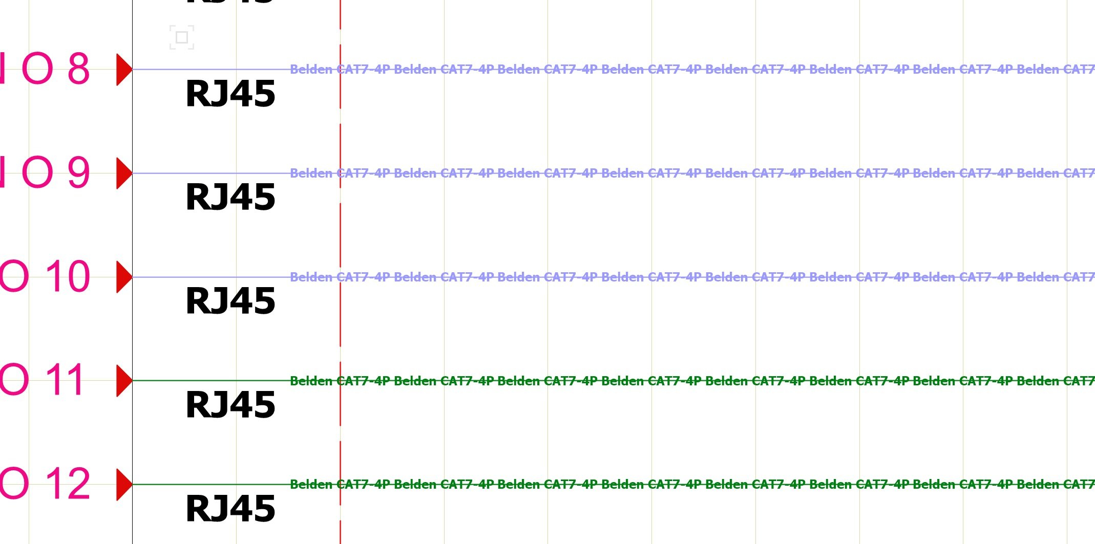
Hi all, Just another quick blurb regarding this. In a more direct look at the issues in this thread, here is a partial solution I have come up with regarding cable types. My problem stems from my requirement to maintain existing cable numbers from the original drawing, adding a new numbering system that follows an established standard (ANSI TIA 606-B), displaying the cable type, and creating a visual reference to signal flow using color. Unfortunately this requires 4 parameters where ConnectCAD only has three. My work around turned out to be creating new line types for cable types. Then color coding the signal type for the particular flow of a connection. e.g. I may have a network signal for a Dante system, and a network signal for QSYS, or Waves Soundgrid. All run on the same type of cable, but different signal types. I created a line type for Beldin CAT7-4P and then in classes, select the line type and color for each signal. This allows me to specify the cable type for each connection, and maintain a color reference for signal type, creating an easy visual reference. That being said, it would be great to have a drop down menu for signal type when selecting the circuit. While a device connection can be edited to default a signal type, the attached image shows two different signal types in one patch bay for RJ45. Don't really want to have to customize each patch bay, but rather select each signal type once the connections are made without having to reference the classes to remember what the signal name is for a particular cable. (lots of different audio signals, with the same color, but many different cable types) Hope this helps..... James

-
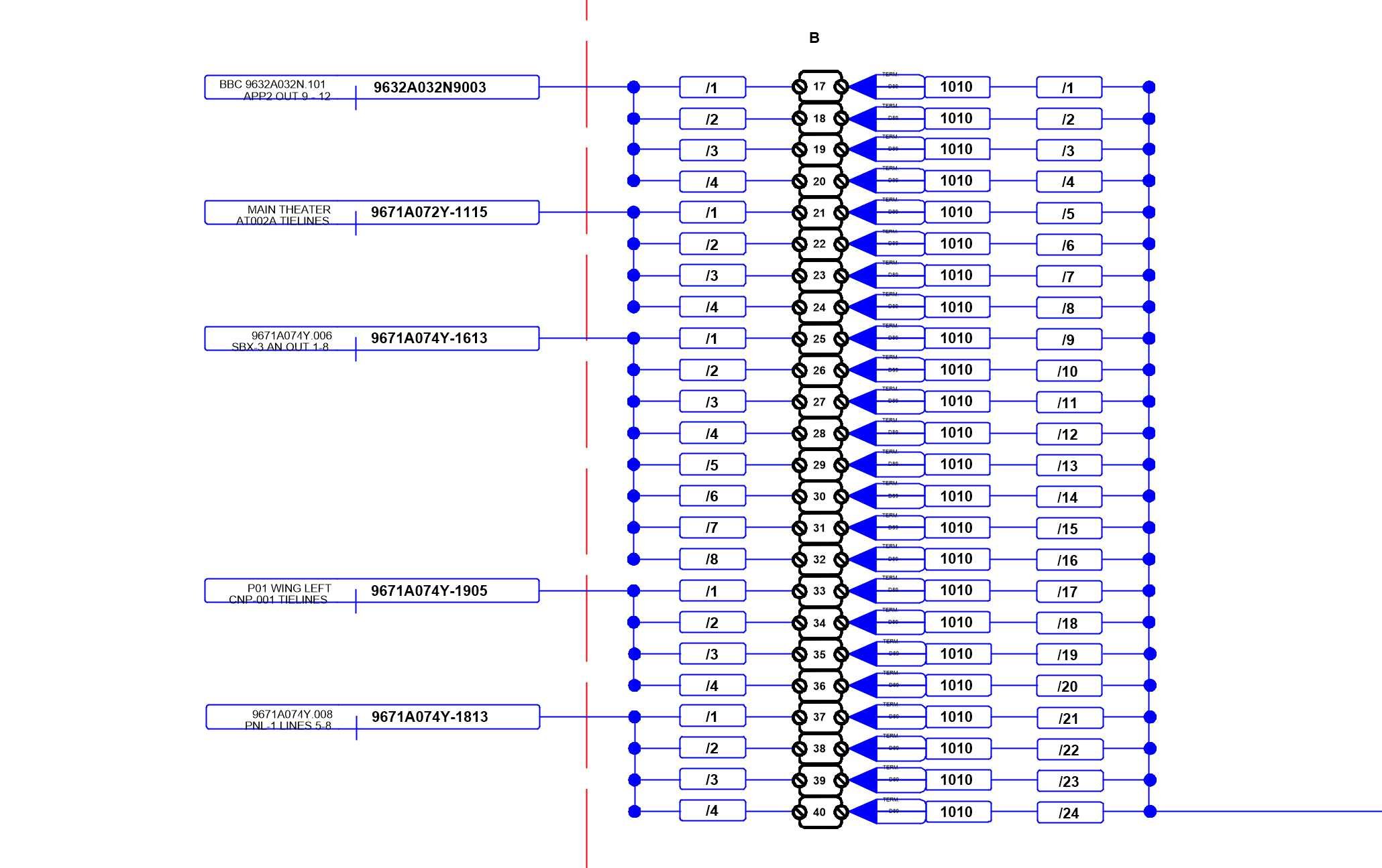
Hi all, Adding a Big +1 here. I regularly create drawings with multi-line cables of up to 32 +/-/G sets for large audio installations. A Canare MR202-32AT cable might come out of a terminal block in a rack and run to another terminal block in a rack in a different location. With the terminal block device, I can use a single cable to represent one of the 32 sets, but if that runs to another rack, I have to connect 32 terminal blocks individually on each end. As well, it does not allow me to represent the MR202-32AT as a single cable, but only as 32 separate 25awg cable sets. I know this is a big ask, but it would be nice to identify the cable type, and select how many lines it has. Then somehow have a break-out/break-in point at the line termination. As an example, a 32 set cable that runs to a terminal block in a rack is labelled xxxx. When you click to connect it to a device, it recognizes the number of lines in the cable, and then asks for 32 different connections. Labelling each of those connections in turn xxxx/1, xxxx/2, xxxx/3, etc. I could create this as a separate device, but I don't want to confuse any of the installers. I've attached a small example of the things I convert from our designers. They use CAD, but we use VWX, so I re-draw them so it can be viewed on one drawing for the end user. Any sort of cable type selection, or as mentioned previously in this thread, a .txt file that can be edited would be a great start. Comments? Thanks James Chipman

-
Please disregard the previous topic with the same name, in fact, could someone please delete it? This is the real question. As I am sort of new to ConCad, this may be a normal thing and I'm just paranoid. I am finding that almost all of the objects on my schematic layer are being duplicated in place at least twice, needlessly bloating my drawing. When I look at the device report it only shows a single device, but on the actual drawing, there can be as many as 4 copies of the same device on top of each other. Is this a thing? Does it have a relationship to Layer options? Going back to previous saves, it seems like when I created another layer, it just copied a bunch of stuff and dropped it on top of itself. I'm really confused.
-
Hello all, Does anyone know how to expand the number of blocks on a din rail terminal? I have to draw a 150 port din rail, and the only way I have found is to draw 3 48 block units then go into each separate block and change the name. TB.02.1-48 creates fine, but I can't create anything bigger. I can create TB.02.1-48 again under that, but then have to go into each block and re-label it. conductor Also, anyone have a suggestion on documenting a 3 conductor wire into a DIN terminal? I would like to show all three wires on the block. As well, any good ideas on how to make an internal jumper on the output side of a block? ie. jump TB.02.27 to TB.02.29 on the output side? Thanks for any assistance Chippy
-
Hi all, Just starting to get into ConnectCad. Been a user of VWX for years. Does anyone know a way of increasing the number of socket definitions in the device builder? I could just build a custom device, but I would like to share them with the community if possible. If I spend the time to create a device with more than 12 types of sockets, I'd like to spare someone the time to do it over again. Any thoughts?