A2M
-
Posts
31 -
Joined
-
Last visited
Content Type
Profiles
Forums
Events
Articles
Marionette
Store
Everything posted by A2M
-
My question leads to another one. I created a class system by "batch" (sorry, I don't really know the technical vocabulary in english, I mean I have a set of classes for all the concrete works, a set for the wood works, one for the exterior cladding, one for plastery, and so on). That's what appears to be the best organisation regarding my preceding experiences. Some of the walls are "trans-batch", for example, a wooden frame wall mixes components from the woodwork classes set, from the exterior cladding set and finally from the plastery set. So, my question is quite simple, in which class are you used to put the global wall? PS: to explain the context, our office was working in 2D and I try to change that and bring a better use of VW...
-
Hi zoomer, I finally decided to create my own symbols. It's a fight to understand how to create a nice elevation viewport in the sheet layer, but I'll start a specific thread for that. When you design your own window for example, how do you set the properties of the glass sheet to have it semi transparent in the viewport? Thanks in advance!
-
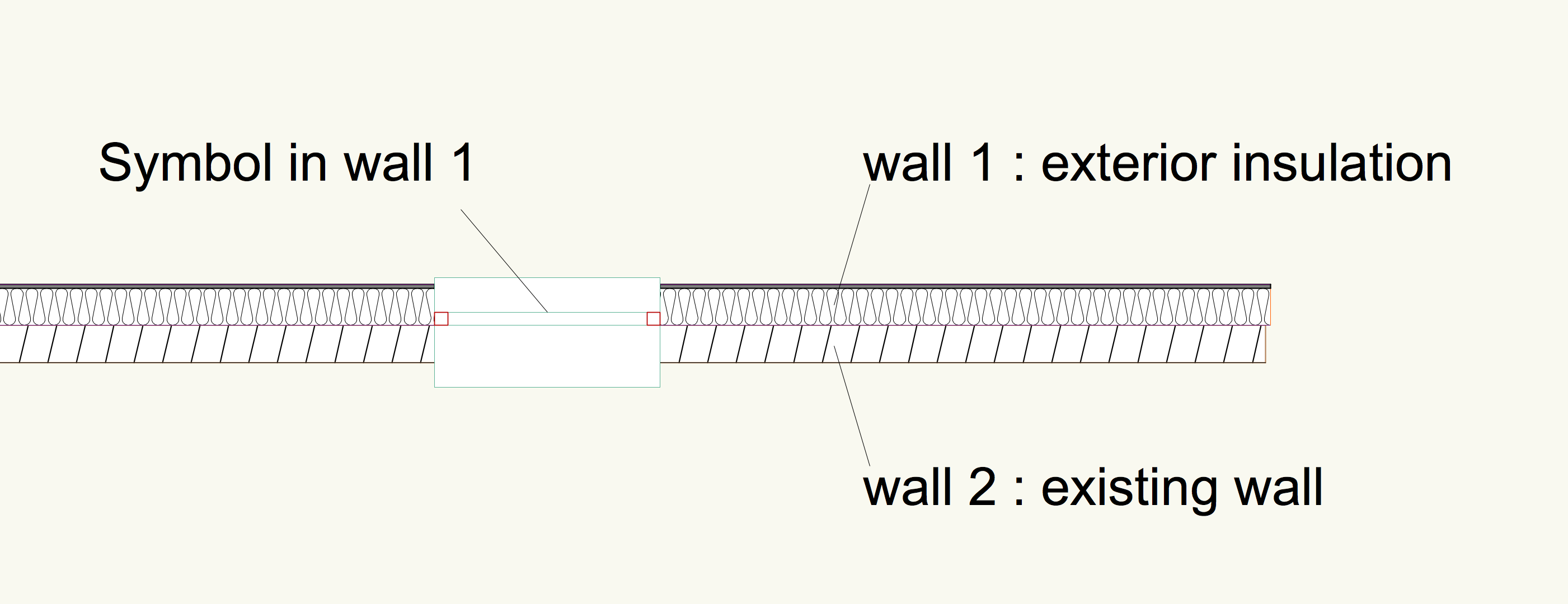
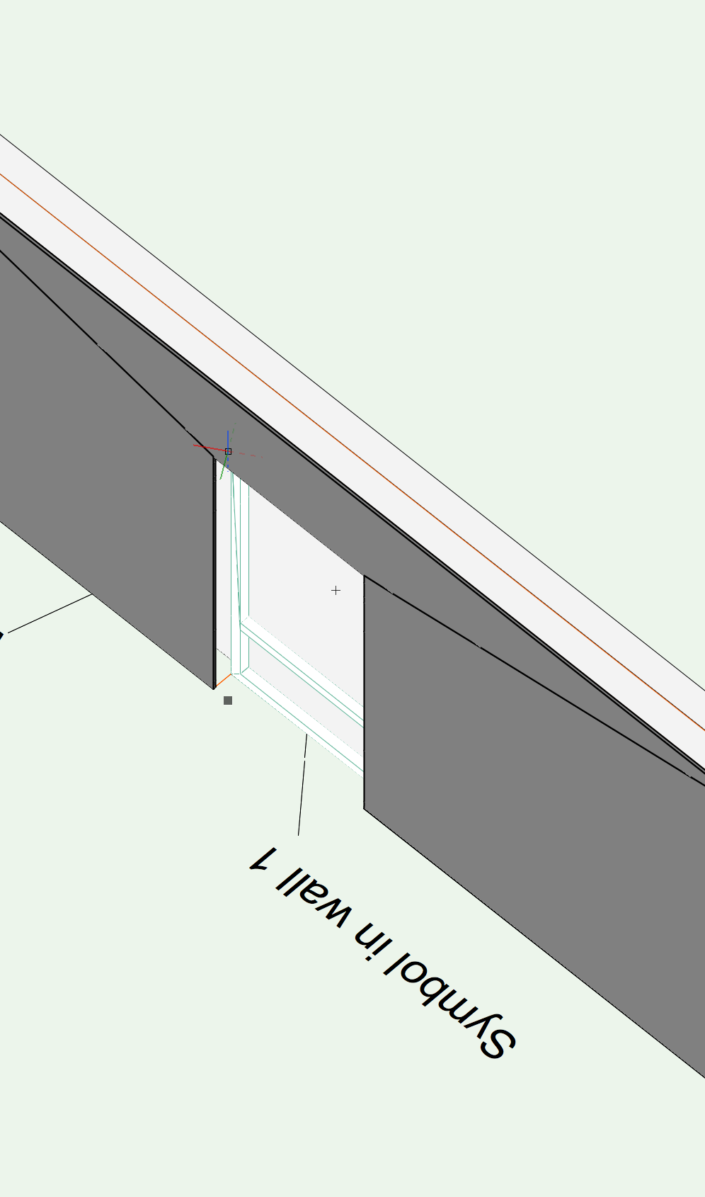
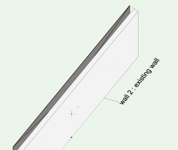
Hy all, Using a background from a geometer, I want to differenciate the existing walls from the ones I create (We're insulating the old walls), I want to know if it is possible to still have two different walls touching each other and then that a symbol (door or window) inserted in on of them can make the hole in the second wall... I probably have to create a ghost symbole of the same size that the first one or to merge the two walls in one. Thanks for your answers


-
Thanks again for all your answers! As I can see that there is a Python section in the forum, I can imagine that VW is written in Python, maybe originally in C++??? Anyway, as a wall can be a wall with or without component, I can imagine that there is a class for a component and that a wall is just an upper-class of the component class. I can imagine also that the insertion tool can be inherited to the component class with not a big effort. I don't really need an offset, just the same tool as now, but applied to each component (such that you can align the symbol on the component of your choice...). I think I won't use the PIO's for windows and doors cause the drawing options they offer don't really fit what we're used to. Another "dumb" question (maybe I should write a new post...), if I try to make a 3d model of the building, it's because I want to simplfy the drawngs of the sections and façades. I used the "create a section" command (créer une coupe in french) for a first look and the result is really bad (I try to explore all the options of the section viewport but nothing makes it better). I imagine you cannot teach me here how it works, but maybe you know where I can find some tutorials.
-
Thanks for all your answers. I'll try the option "use symbol geometry". Still, I can not understand that the developpers have not thought of that, it seems to me like basics, when you insert something in a wall, it is always a door, or a window, and you want it in a precise position. And as I can imagine the programme it shouldn't be complicated to code... @ zoomer: Can you explain what you mean? Are you talking of vw tools? With a picture if you want, might be a shorter explanation 🙂 @Pat Stanford Can you just tell me what pio mean? I imagine it is something like pre integrated objects... just for my culture!
-
Hy Guys. Let's say I already have all my own windows symbols. Suppose also that the origin of each window symbol is on the internal face of the window. I want to insert these symbols in a wall with multiple components, let's say concrete and an exterior insulation to make it simple. I want the window to be at the interface of the concrete and the insulation. In the insertion symbol options, it is only possible to place it in the centre or on the right or left side of the global wall. (see drawing attached!) Is it possible to place it relatively to one of the components? I know it is possible to enter the edition of the symbol and change the origin. The problem with that is that if you change the composition of the wall (you add an interior dubbing for example), you have to change all the symbols. If you can define one of the component to be the reference for the insertion of the symbol, then, you can change the composition of the wall as you, the symbol will stay on the right place. Thanks in advance! SKMBT_C22020021818580.pdf