Poot
-
Posts
133 -
Joined
-
Last visited
Content Type
Profiles
Forums
Events
Articles
Marionette
Store
Everything posted by Poot
-
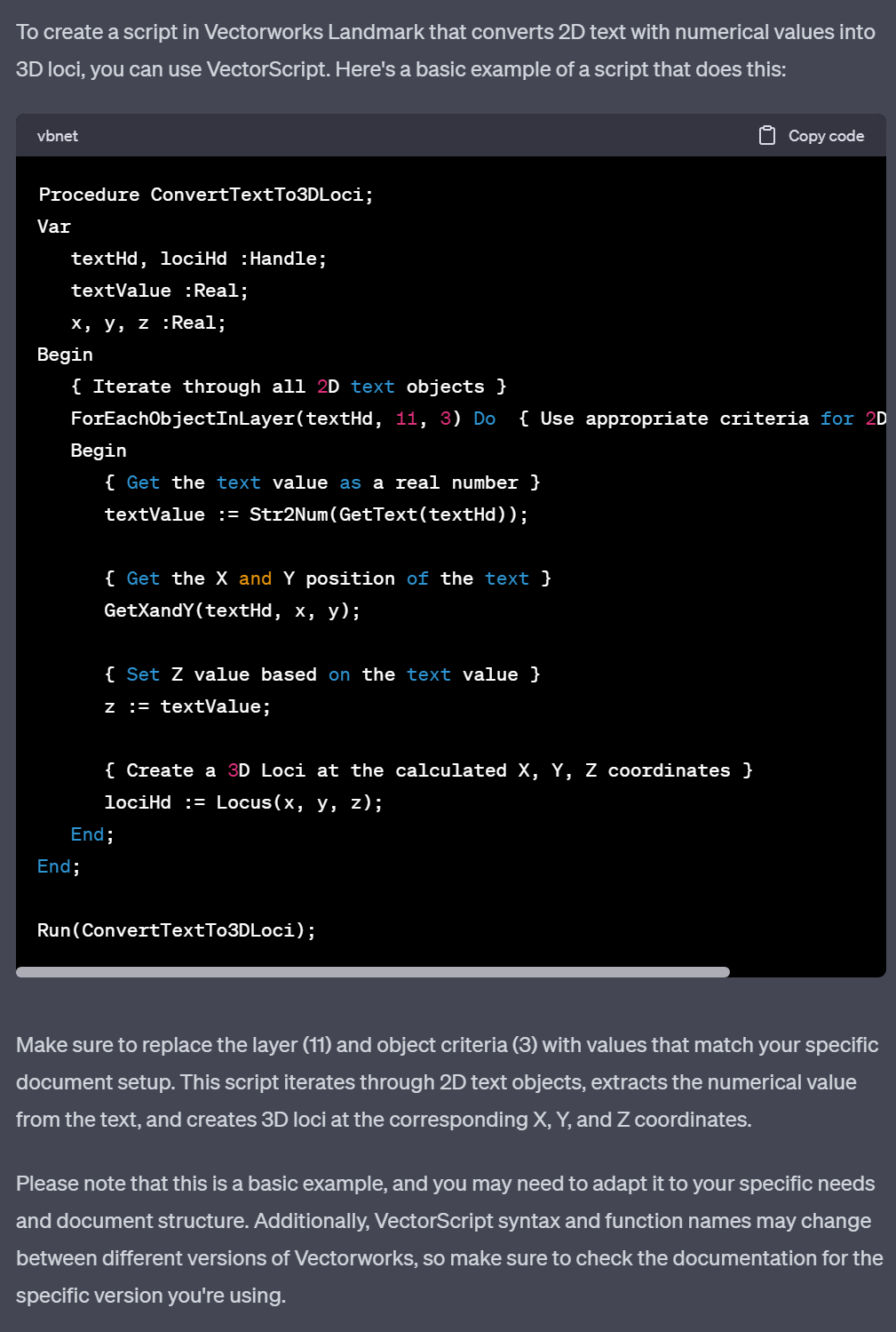
Writing Python scripts for Vectorworks using ChatGPT
Poot replied to Christiaan's topic in General Discussion
I've just started using VW again after a long pause and move to a new country, so I thought I would try asking GPT to write a script to help convert some text with heigh coordinates into a 3d loci. There is a marionette script here for that...but I had issues getting the nodes to visually scale properly ( the buttons are tiny if I bring them into my drawing) . Figured a script might work....so I just have to set up the layer structure in the script and try it out. In theory, GPT should be a huge asset to help programming noobs....and even for those who are handy....to really create some useful parametric features for things like 3d modelling. It will be interesting to see if it can also help automate translating different materials (e.g. converting landscape area styles to hardscape styles...since I basically only used landscape areas until recent upgrades to the hardscape functions) --------------------------- Procedure ConvertTextTo3DLoci; Var textHd, lociHd :Handle; textValue :Real; x, y, z :Real; Begin { Iterate through all 2D text objects } ForEachObjectInLayer(textHd, 11, 3) Do { Use appropriate criteria for 2D text objects } Begin { Get the text value as a real number } textValue := Str2Num(GetText(textHd)); { Get the X and Y position of the text } GetXandY(textHd, x, y); { Set Z value based on the text value } z := textValue; { Create a 3D Loci at the calculated X, Y, Z coordinates } lociHd := Locus(x, y, z); End; End; Run(ConvertTextTo3DLoci);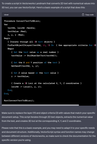
-
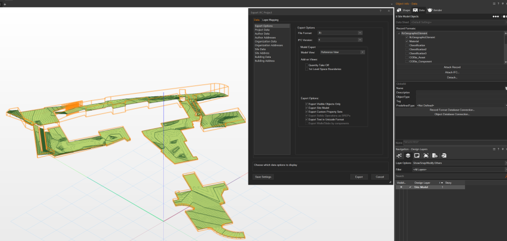
Hi @Mihail Rizov Thanks again for the quick response! That seems to have helped. I still have all but 1 area showing up. Did you have all site models on the same design layer as well, or did you need to put one on a seperate design layer? The area which has the IfcSiteModel record is not showing, while all others are. 🫠 ****edit: I tried changing which area used the IfcSiteModel tag, and it worked as planned. THANK YOU for the help! 😀 not sure why the area below didn't work. ****

-
Hi @Mihail Rizov Thanks for the quick feedback. I have tried both with IFC2x3 and IFC4 with the same results. At best, I get 1 of the site models showing in the IFC. I have tried assigning their design layer (they are all on same design layer) to both Site (which gives 1 area in the IFC) and to a story (no areas show). I've attached the file as it stands with IFC2x3 so perhaps I am missing something? Thanks very much for your help! Matt Multiple Site Model to IFC.vwx
-
I just tried opening an old file from VW2021 with multiple site models, and it is not working anymore using this method, but it could be due to problems converting the older version into VW2024. There is another topic with IFC export procedures here which might help but so far has not worked with my prexisting file: Hopefully we find a solution!
-
I've recently opened a file in VW2024 with several site models that I created back in VW2021, and am also having an issue where only 1 site model shows up in the export. I've checked with both IFC2x3 (assigning IfcBuildingElementProxy) as used to work in VW2021, and IFC4 (assigning IfcGeographicElement) to no avail. I am sure opening an old file and converting to the new version is causing some issues...but can't really figure out why it wouldn't work.
-
I have experienced similar problems, where editing proposed contours is totally unreliable, and just causes more problems. I have not used VW yet on a huge number of projects, and none of which required a cut/fill analysis so I just edited source contours or existing first sometimes to get clean results. Or, just used various site modifiers rather than try to edit the contours. Not sure what the issue is...
-
You can do what they show, but it requires creating your own custom 3d plant symbols from 3d geometry. It is not too hard, but would take some time to set up to have several sizes/colours as shown in the video.
-
Agree 100%. The tool is close, but still very awkward to use practically without a ton of point by point editing for correct 3d, or with inconsistencies in how segments are joined (or not joined as often is the case...) and placed as walls slope and step downwards (eg. flights of stairs). Easy to complain, but am hoping this tool gets a bit more polish as along with the expected developments of a curb tool, this will be that much closer to having most of the fundamentals covered in a good way.
-
Very nice! It does seem like multiple/overlapping viewports is the best way to get more nuanced effects and visual control. Thanks for the good tips!
-
Nice! Would there be any way to have the site model white below grade?
-
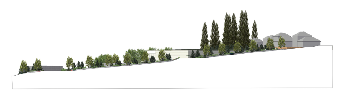
Hi Everyone, I am just wondering if there is some secret trick I am missing to create sections like the one below, without having to trace a white polygon in the sheet layer? Most often when drawing large/non-detail principle sections it is not necessary to show the construction below-grade. I understand how to control this with layers and classes within landscape areas, but there is always extra geometry of various thickness that I remains. Using just the site model line means seeing the site model in the background if it is extended. Drawing a polygon overtop is not overly complicated of a workaround, but just thought I would ask 🙂

-
ah right, probably a bug with the update. Seems to happen especially before any service pack fixes. Maybe @Tony Kostreski can report the bug? Not sure who is best to refer to 🙂
-
Have you tried the usual culprits/bugs of having the site model on, or being in 3d view while trying to adjust this?
-
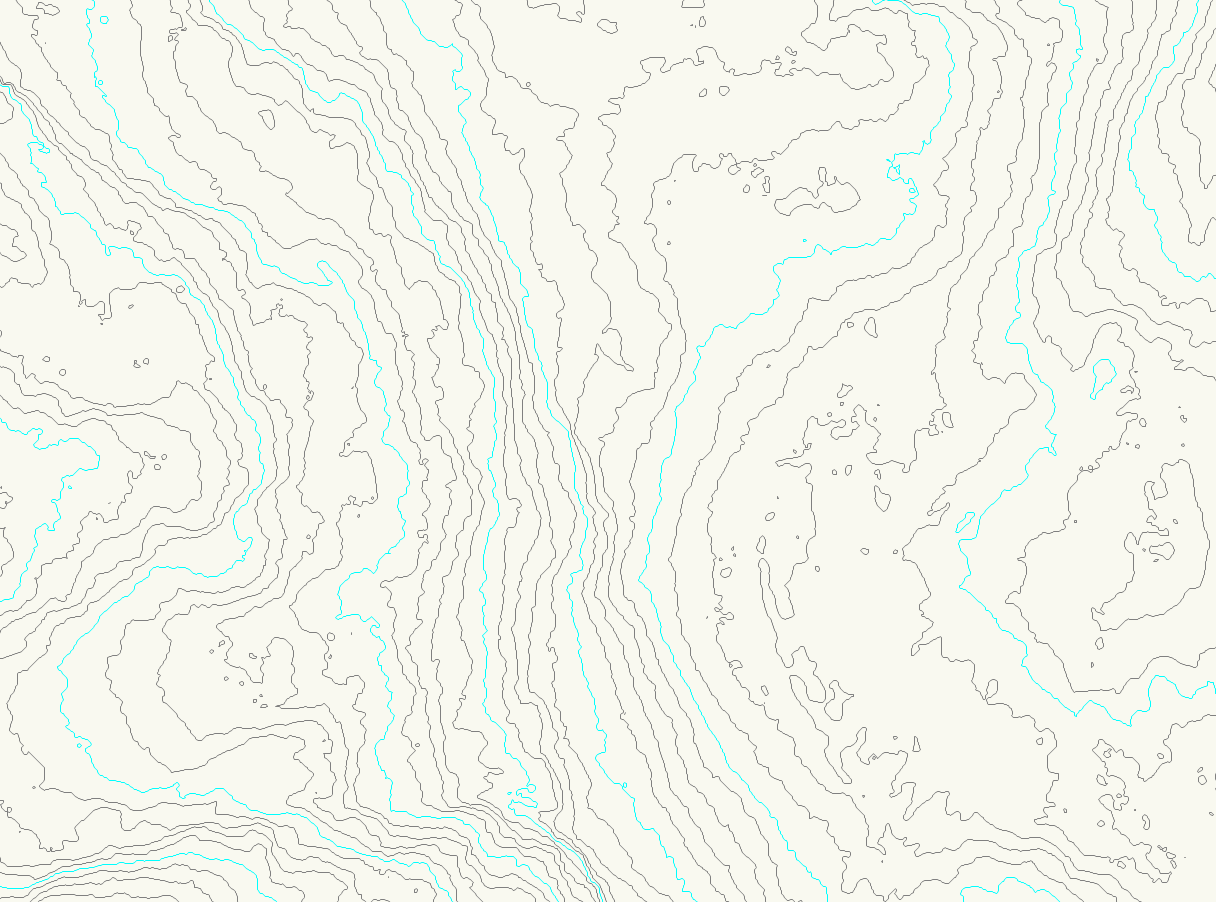
Georeferenced file collaboration - Export workflow
Poot replied to Carol Reznor's topic in Site Design
I haven't done much exporting from VW back into AutoCAD, other than 3d contours taken from site models and simple geometry, which is pretty straightforward. Other than 3d elements (furniture, etc) which you would not want to export to someone working in 2d, it should be straightforward. Exports, from any discipline, should always be true north to avoid problems. You can export with an internal project origin, which works without problems, but even when working with an agreed origin point and rotation angle this opens the doors to problems with certain programs. I always use a test file export at the start of projects, with the building footprint from the architects and simple landscape geometry to check with other disciplines if they align properly with their drawings. I would suggest doing this to avoid complications, as its very easy to do, and can clarify any issues very early on. -
Yes, I've used this second method, but it would be nice to have some control over the number of faces/simplification level. I've been unable to do so yet, either from converting a sphere into a mesh and trying to simplify that, or from converting it into a 3d poly.
-
I've been looking to make similar geometric shapes for bushes/shrubs, but not sure if there are existing symbols to copy from. Can do this with trees to a degree, but I have not figured out how to do this in 2021 to have a faceted sphere like that. Would be nice! I guess to do this you create your 3d shape (e.g. sphere) and convert it into a 3d poly and bring that into the 3d symbol definition for the plants you're working with. Not sure if there's a pre-existing style like this already.
-
If you cannot get the heights from them, which is actually their responsibility, then I'd probably take the contour option. should give you better results.
-
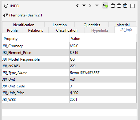
Hi Everyone, I have also posted in the Site Design forum, but thought there are others who might be able to help. I'm just coming up to speed with the BIM aspects of VW, and wonder how I would work to add custom properties so that I have exported IFC elements (in this case mostly landscape areas) which follow a set naming structure as seen below. Forgive me if this is a basic ask...but I just haven't done this before. From what I gather, you need to create some custom records which can be used within property sets, but I am a little fuzzy on the best process of doing this so that everything comes together as you see above, in one category. I'll be working through tutorials/youtube, but any help/tips are greatly appreciated!
-
@MullinRJ, In my best imitation of Denzel Washington (Frank Lucas)... Thank you!! I think that this is useful enough where it would be nice to add in the 'simplify poly' part of the menu, since it is very often you get a lot of small contour 'islands' that bulk up the file.

-
Hi Everyone, I'm wondering if any of you have added a price entries to IFC exports for landscape areas before? I am basically looking to make landscape areas with only the most basic info like below, as well as some general properties which will come with them that can be exported into IFC, and taken out into Excel in collaboration with other disciplines working within Revit. From what I understand, you have to create a custom record for price, and then attach that record in the data manager. I haven't had the time to test this yet, but was hoping someone here might have done so! Thanks for any tips 🙂

-
Hi Raymond, and thanks for the quick reply! I was indeed thinking of 3d poly's with more than 3 vertices, often coming in situations where we get terrain models/contours that include many (sometimes hundreds) of very small/short 3d poly's. It's not an absolute crisis, but combining a script that removes them with simplification of the poly's makes large models much easier to work with. Appreciate the time and help 🙂
-
@Pat Stanford I am wondering how I would modify this script to do the same process of weeding out short 3d polygons? (i.e. from a huge number of 3d contours). Is this possible?
-
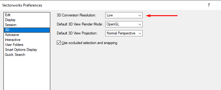
Change your 3d conversion resolution to 'low' and the exported IFC file size will drop.
-
double post.
-
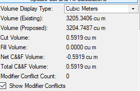
Hi everyone, I am wondering if there is a feature to add the expansion ratio into cut/fill calculations, for areas where the 'cuts' are blasted out from solid rock, and thus have an expansion ratio greater than 1:1 . In this case, blasting 1m³ of solid granite does not produce 1m³ of blasted rock, but more since that has now been blown to pieces with lots of gaps between them. Civil 3D has this function, but I was hoping there is also some similar feature in vectorworks? Thanks for any tips.