


Poot
-
Posts
134 -
Joined
-
Last visited
Content Type
Profiles
Forums
Events
Articles
Marionette
Store
Everything posted by Poot
-
I don't have any additional drivers for my MX master @zoomer It can pair with up to three different devices via Bluetooth, and there is no adapter or special drivers needed. You can of course install the software to customize keys/buttons more easily, but it isn't drivers as far as I'm aware.
-
I have had a new problem come up with WMS satellite imagery. Everything worked fine setting up the cropped image, but when I deleted the crop to create a new one it is no longer working to get any image, even with the same area, larger/smaller size or resolution. It even stopped working with a new blank file... The coordinate systems match, and the default service works fine... But it is a big PITA to have the geoimage stop working (continues to work with previous/different files) Not sure if anyone has figured out common problems that are not resolution, crop size, or coordinate system?
-
Site Modeling - Trimming Contours imported from other programs
Poot replied to Jeff Prince's topic in Site Design
Great input! I would not have thought about this. One big question is, how/where are you getting your source data with relatively clean points? It is pretty common for municipalities/govt. to provide height data as surfaces, contours, or point cloud....and not so much cleaned up points. I haven't really worked with point clouds, so I am not sure if you're starting from there? From what I have seen they take quite a bit of cleaning to make them good for use. -
The workflow/tools are not identical, so you don't go about it exactly as you would with a feature line in C3D. I don't use edge lines like I would feature lines, because I have other tools. If you really want to, you can split your line and adjust it, but its not ideal. The majority of time I am wanting/needing to control grades between points is along hardscapes, pathways, roads and ramps - all of which you can control either as a single slope/grade or between points/stations fairly easily in the OIP. I am rarely looking to grade open greenspace this way, or in ways that can't be achieved by grade networks and site modifiers. However, I think the open edge tool could benefit from the same kind of dialogue box as a feature line if the VW team wants to grab C3D users more easily...or for situations not covered by the other tools...but the desire to use it also comes from habits developed by using C3D itself. I'd suggest dropping the suggestion in the VW public roadmap, since it might be a relatively easy feature to include.
- 11 replies
-
- 2
-

-
- grading plans
- landmark 2020
- (and 3 more)
-
You could probably go about this in a few ways, but I might suggest grabbing the important info from the detailed model of the point cloud (e.g. road geometry) by using something like grade objects or stakes set to follow site model, and then copy those to use when creating the less detailed, but faster model. There is a whole other profession that usually deals with this kind of task on the mapping/aerial surveying side of things because its a complicated task best suited to programming. You might be able to find/create a script that filters/evens out the peaks from selected areas of the point cloud.....but not sure if this exists.
-
What was the issue that fixed it @Esa K?
-
Very late reply @Elin as I came across this looking for something else, but you can do this by editing contours in your site model, or by using what is now called the 'open edge line' tool in the site modifiers toolset (previously called the contour tool when you asked this question). Like feature lines in Civil3D, you can set a grade across the entire line/curve/geometry as %, ratio or angle....and also edit individual vertices. You don't get the list of point values as in Civil, but thats not really needed when you can see the object in 3D (which is much more of a pain in C3D).
- 11 replies
-
- 1
-
-
- grading plans
- landmark 2020
- (and 3 more)
-
Yes, this is what I am trying to do, but with WFS that are based on GML as opposed to SHP. Out of curiousity, do you have a paid ESRI account/arcGIS subscription or what databases are you connecting to in order to access the feature layers? The public dataset here in Denmark has national height data with +- 3cm accuracy, but I am sure it varies a lot regionally in the states, or even by municipality?
-
Do you have a grade limits placed around your site? Or at least the area your grade objects are within?
-
I agree with @Jeff Prince. Unless you are placing existing plants that are not trees...which I guess is possible. If you have a list of many trees and put it into a spreadsheet with relevant headers you can use to sort them and populate the right info.
-
Done! It's hard for me to know how easy/difficult it might be to make the GML format work with VW, but hopefully it's possible! It would definitely mean not having to use/learn programs like QGIS for many, and make VW a pretty great GIS Tool for planners as well.
-
Do you get the "unsupported service type" error when you have selected the WMS service (as shown in post above)? or only when you connect to the WFS?
-
Thanks for the link Tamsin. I had checked the seminar out when it happened....so good to get the link again! I am basically looking for something like the ArcGIS Feature Layers that allow you to directly import vector based data/geometry (contours, road geometry, buildings, etc) within Vectorworks without the middleman, skipping the process of downloading and importing. I believe there was a seminar on this. Many countries have agencies/map providers that offer Web Feature Services (WFS) which function like 'feature layers' from ESRI, but using the GML file format, which is not currently supported by vectorworks, rather than shape files. This is the case at least for Germany, Denmark, but many others as well including datasets from the Ordnance Survey site you linked. I think it is the case for most Europeans countries and municipaIities. I know @Scott Campbell worked to make the Norwegian SOSI format accessible through VW via SosiWorks, so I am hoping there might be some future where GML file format can be used for WFS. I know there are some posts on the german VW forums about this issue, and I am sure elsewhere I know VW has developed a good relationship with ESRI that enables editing feature layers, but it would be nice to see GML support make accessing/selecting data so much quicker and easier.
-
I can't seem to find what the technical details are for the Helsinki map service...and usually orthophoto/imagery/raster web services work. Can you provide the link where you find the technical details on the map service? It can sometimes depend on whether you need to create an account with the map service portal, and add details like a username/id/password into the URL of the WMS/WFS for it to successfully work.
-
Site Model not Updating to Align with Hardscapes. VW 2024.
Poot replied to Jack2022's topic in Site Design
This also gives you an idea of how they work. You are basically detailing your heights/3D with the grade objects (also with stakes if you want) which are connected, making it much easier to control for multi-sloped areas. It might still work to use these in combination with slab-like hardscapes (slab/aligned), but in my experience, unless you absolutely need something to function like a flat slab, it becomes more effective to create what you want with several grade objects (along boundary, across for slopes, etc). Path and road tools sort of automate this process for us.- 20 replies
-
- 1
-
-
- hardscape
- hardscapes
- (and 1 more)
-
Site Model not Updating to Align with Hardscapes. VW 2024.
Poot replied to Jack2022's topic in Site Design
Take a look at Using site modifiers with hardscapes . Unless you need a hardscapes to work like a slab, path or road, you should now use them like a landscape area draped on the surface like Tamsin mentioned. Use grade objects and stakes in a network to adjust your site, and snap the hardscapes to the site. This is the way.- 20 replies
-
- 1
-
-
- hardscape
- hardscapes
- (and 1 more)
-
Hi everyone, I am just wondering if anyone has worked with the GIS tools in VW to use WMS or similar to get 3d contour lines? I have seen shape files and other geometry, as well as raster based images for elevation maps...but have not worked myself to get these directly through Landmark's GIS tools. Usually I have downloaded these from various sources, and imported. Perhaps you might know something about this @Tamsin Slatter ? I am in Denmark now, and here the government providers for WMS use the GML format, which also complicates things since VW does not play with GML so I can't see what is accessible. Ideally, it would be great to be able to import sections of 3D contours from a web service...and I think its possible, but perhaps not through the GML based web services here in Denmark (also the same for Germany and many other European countries).
-
Good routine. Definitely would be nice to share 😁 Developing these workflows often take some time to work out and can add good functionality.
-
I agree as well, as the certifications are very comprehensive. Together withthe universtiy, you can also filter your search for 'classes' which cover what you are specifically looking for (and take anywhere from 1-2 hours). The 'essentials' seminars are good for people who are starting completely from scratch. Otherwise, you also have those like Jonathan Pickup who have starting courses and training available as well.
-
As @Jeff Prince mentioned, I think that scripting would get you exactly what you want....but it requires some expertise. @Pat Stanford might know if someone has already come up with something like this, but you can also search the scripting/marionette forum to see if you find anything. Otherwise, you might get there by creating copies of the stake objects onto different layers, one each for existing and proposed.
-
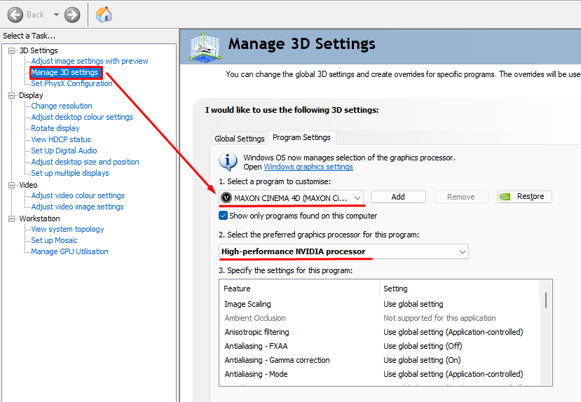
Many CAD programs don't benefit as much from multi-core CPU's multithreading capabilities because the sequential/history based nature of our instructions while drawing (do this, then this, then this, etc) which make better use of more powerful single cores, rather than many less powerful ones. 3D modelling can make use of multiple threads, but our normal drafting is not purely 3D, and heavily sequential.....so even with a super fast GPU and 14core CPU, those wont help as much as fewer cores running at a higher frequency. For Windows, you access the nvidia control panel in the start menu (just type it in), and set the 3D settings as shown below. This is solely for 3D functions....so very helpful for rendering and 3D of course.


-
IFC Export Georeference Doesn't Match Model Georeference.
Poot replied to Jack2022's topic in Site Design
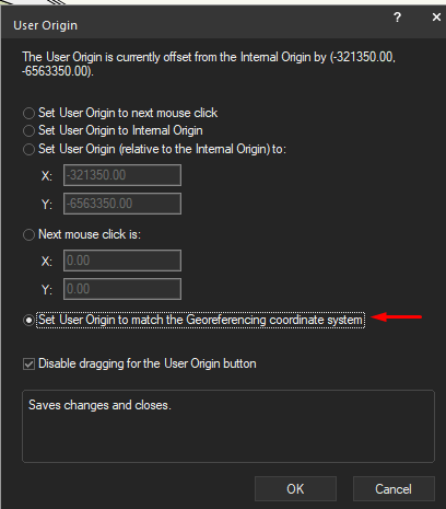
If I am not mistaken, you should be setting your User Origin to set the project coordinates/origin, and not adjusting the Internal Origin numbers. If you are using a specified coordinate system, the internal origin coordinates should be created automatically for the drawing. You're images show there might also be an issue with the unit precision for the document/coordinates....(there are 3 digit differences indicating some issue between metres and millimetres). Not sure why you'd get different values though. I have exported several IFC models using the 'project coordinates' as the User Origin, with the expected results. I have never done the opposite, and adjusted the internal origin. -
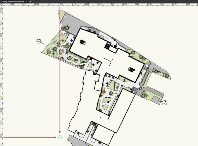
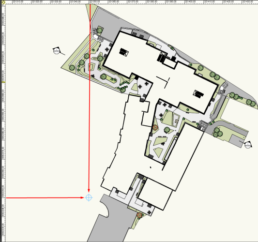
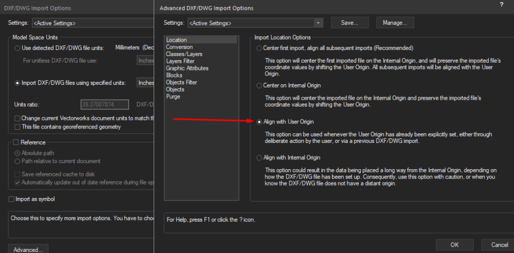
Three questions: Have you set your drawing georeferencing to use a coordinate system like @TeeMuki is using? (File->Document Settings ->Georeferencing) Have you set your user origin to match the Architects 0,0? Is your drawing/file set to use the User Origin or Internal Origin right now? It sounds like you are working with the Internal Origin. Drawings from electrical, roads, engineers, landscape architectst are almost always in world coordinates , whereas architects drawings are almost always using 0,0. If you haven't set your user origin to match the architects, you should probably do so. *unless there is another "project origin" agreed with other disciplines. then the architect needs to use that too. Once you have defined your user origin to match the architects 0,0 see below. CHANGE DRAWING to use USER ORIGIN (self-defined) should be small values on the X/Y rulers To import Architect DWG set in custom/project 0,0 that is the same as your drawings USER ORIGIN CHANGE DRAWING TO WORLD COORDINATES (aka using INTERNAL ORIGIN) typically large values on the X/Y rulers. compare coordinates between above/below

-
You need to have a coordinated origin point for the project (e.g. where does the architects 0,0 correspond to in real world coordinates?) You would use this origin point to create your user origin in VW. Then, when you import a file using NOT in world coordinates(aka architects drawings) you can set it to use the origin when importing rather then the internal origin. If you don't have one set up for the project, you have to sort that out, agree on a reference point in a survey or cadastral, etc. This is best practice for every project, right from the beginning, and makes coordination with DWG or IFC easy regardless of what programs are being used. You should never move things manually, as it's making you liable for errors. As a side note, you should always try to have a user origin for your projects that is within 5km to avoid issues with 3D rendering. The closer it is to your site, the better, for these reasons. It can be something like the corner of a nearby building, or a coordinate number that is simple (e.g. Without many trailing decimal points that come with random locations)
-
Have you tried using the saved view and then opening the palette? Maybe it's not necessary. Yes, I got it to work work fine.


