techecc
-
Posts
12 -
Joined
-
Last visited
Content Type
Profiles
Forums
Events
Articles
Marionette
Store
Everything posted by techecc
-
Equipment Summary Tool bugged? Spotlight 2024
techecc replied to LiteDoctor's question in Troubleshooting
I figured I would chime in here as of March 2024 that this behavior is still present as of 2024 Update 4. -
Custom Worksheets Now Not Able To Add New Column
techecc replied to techecc's question in Troubleshooting
This works like a charm! Oh my god I can not thank you enough. The sheer quantity of work I was staring down thinking about rebuilding all my sheets from scratch. You're a lifesaver. Putting this piece of knowledge in my back pocket for the future. -
Custom Worksheets Now Not Able To Add New Column
techecc replied to techecc's question in Troubleshooting
I've managed to narrow things down just a little bit. It seems that any worksheet that exists in any older VW file seems affected by this. I attached a file that has a copy of my old worksheet as well as a very rough freshly made one that actually works as intended. Take a look. Worksheet Error.vwx -
Hey Everyone, some oddity upon going to do some updating on some custom worksheets I made awhile back. I seem to be unable to link new headers on any worksheets like I previously had. If I enter a new sort in the database header it does not link object data, it instead just copies that field to the whole column. All my old worksheets continue to work but I'm unable to add new columns either by manual text entry of the formula or using the select drop down arrow menu. Am I missing something? Has something in the syntax changed in some recent update? I'm at a loss.
-
Digging into this a little bit I've at least noted a few things. Your custom S4 symbols are made up of 3 layers of nested symbols. Your lens component / body symbols seem to be 2D/3D symbols which add 3d insertion points, which I suspect is causing the geometry oddness. Changing your symbols to be purely 2D-only makes the 3D geometry appear as expected. However this did not fix the pan issue. The only way I was able to restore normal focus function was the replace all the 3D geometry with another symbols 3D geometry after removing the custom lens symbol's 3D. This seemed to only work if I replaced all geometry at the same time. If I replaced piece by piece it would not work. Interestingly enough the symbol I used as reference geometry was a 2022 symbol from my own start file, and that was able to work as expected. I also can confirm that exporting the file back to 2022 and opening in 2022 SP6 does seem to not exhibit the issue from the start.
-
Fair enough. This is just the closest topic I was able to find via search. I'll try and see if I can re-create my problem and start a new thread, unfortunately I can't distribute the file so I'll see if I can get it to happen again on a different file. Thanks.
-
I'm encountering something similar in a current project of mine. Objects that were deleted are showing up in worksheet counts and can not be selected via the worksheet.
-
Hey There, this is behavior I've noticed since 2021 but figured I should bring this up as I'm starting to make the transition to 2023 and this is the first thing I've tested. When adding Data Tags to a viewport annotation layer the auto placement only seems to work on views that are using orthogonal view. If the viewport has any kind of perspective view (like Normal or Wide view) the data tag association seems to completely break and things the objects you're looking at are still in some other orthogonal seeming view. Basically attempting to attach data tags to a viewport that is not orthogonal is extremely annoying if not impossible due to the object highlights not appearing where the objects you're looking at are on screen actually are. Am I missing something here? 440792885_DataTagPerspectiveError.vwx
-
So Mark Doubleday and I spent about an hour on video call last week and figured out where some of these errors are coming from. This mostly related to the fact that the 2 SL positions were created by mirror imaging the SR ones, which causes something to break in schematic view as it references the original geometry. I have attached the demo I put together to show him. Schematic View Test.vwx
-
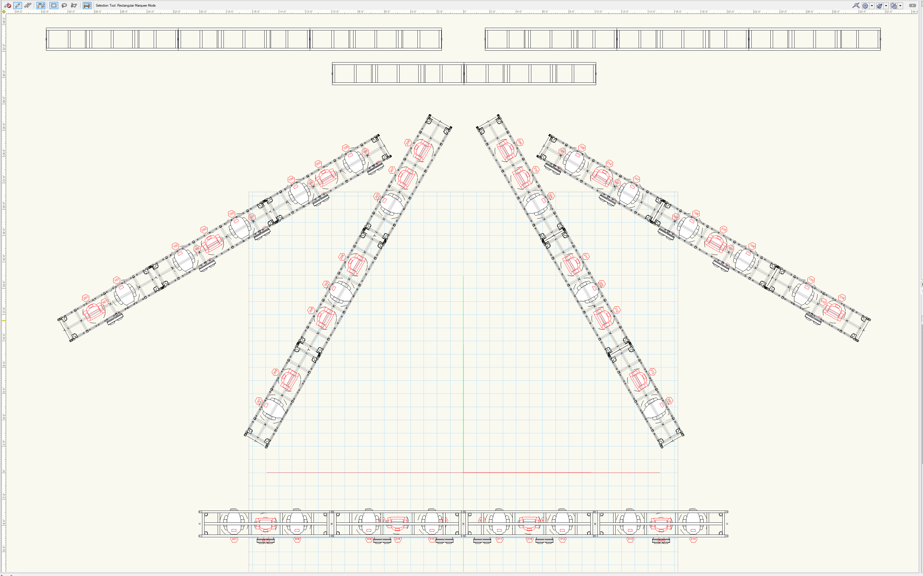
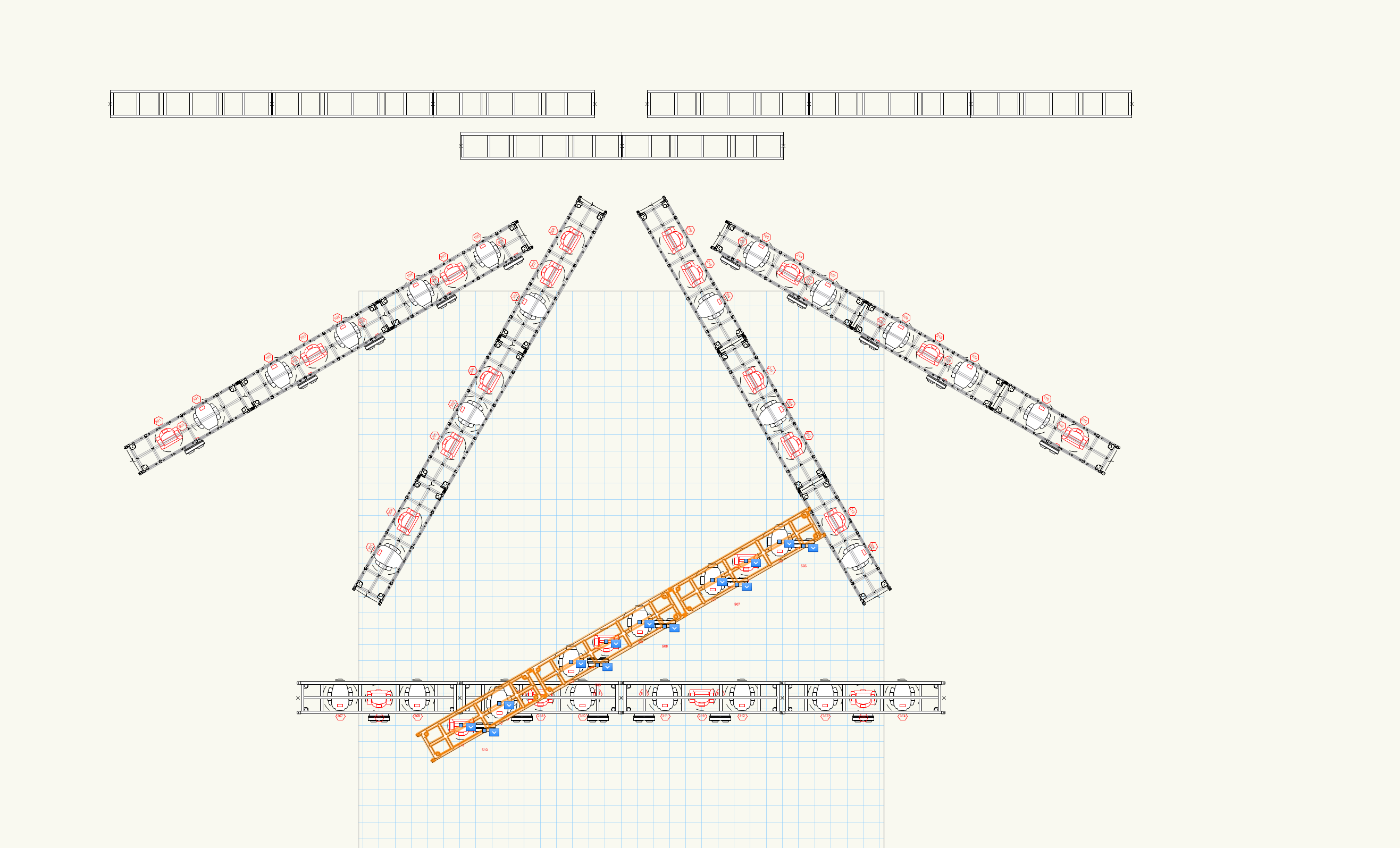
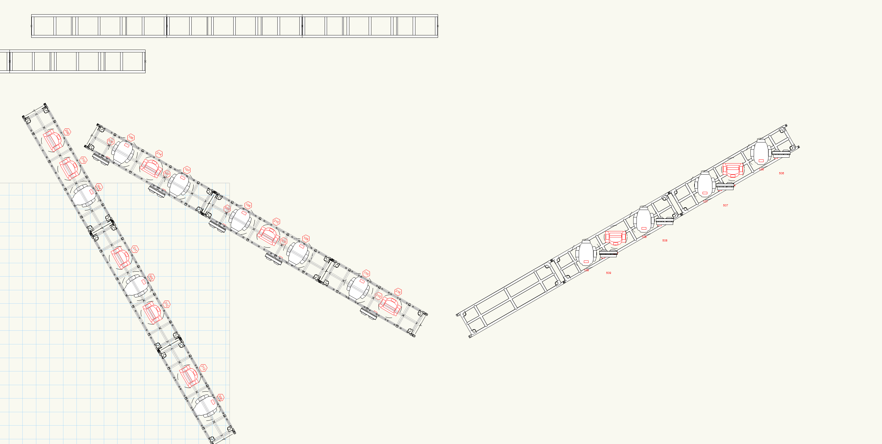
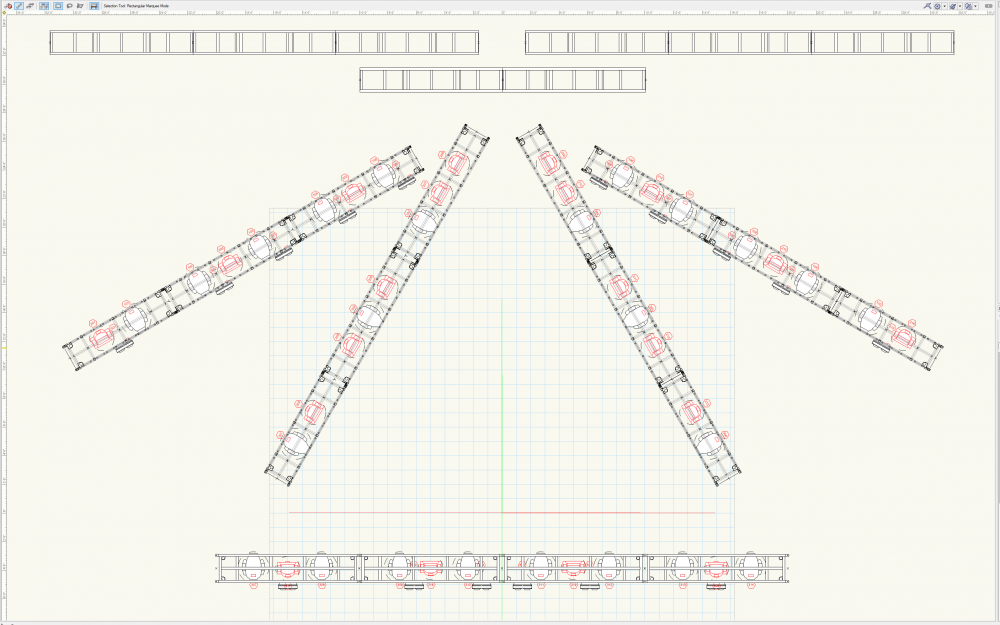
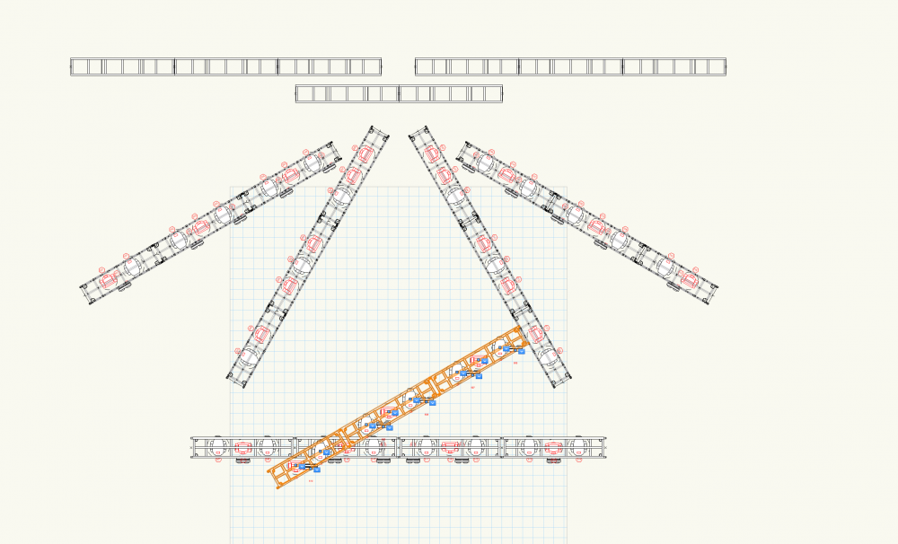
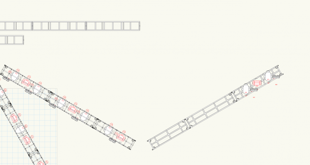
I need someone to sanity check me here. I feel like Schematic View could be beneficial in theory, but I started experimenting with it today and seem to have immediately run into issues. Lets start from today's beginning. Simple truss layout of 30 and 45deg angled positions (image 1). I attempt to create a schematic view of the furthest right truss (image 2). Image shows schematic view as it appeared when created. Now I can live with it appearing centered on the user origin, however you'll notice that once created has incorrect fixture orientation in relation to the truss' orientation and has additionally removed the label legend container. I have been unable to resolve this in any way through my experimentation. The straight truss in the drawing when converted does keep correct fixture orientation but also loses the label legend container. Also moving the position to compare it to the original it seems to have been created in mirror image. The last minor but weird thing is that once a schematic view is created, the lighting symbols seem to appear and disappear depending on how I'm viewing the design layer. Sometimes zooming in makes some fixtures disappear, and even scrolling left to right causes some to pop in and out of view reliably at similar view. ( Image 3 + 4) My intention is to test this on vertical positions next, however I'm not sure I want to take the time as from what I can see the tool feels completely broken even for simple single rotation positions. Am I crazy? What am I missing? Has anyone else run into issues like this? Thanks

-
@M.Graf TH-OWL Thanks! That works much closer to how I intended. Much appreciated. I'm just starting to get a better feel for how the marionette system works. Any sense as to why the file size seems so huge?
-
I'm attempting to make a simple tool that has a few text user input text fields as well as an object that gets its color fill from a drop down menu. All these fields should also link to a custom record so that the information can be put into a report. I have most of this working in a very thrown together manner in the attached file, however there are a few specific things I'm most curious about. 1) How do I structure this so that when I eventually get this to work as a tool the created object is placed at next mouse click? Currently when wrapped object is created at 0,0 2) Why when converted to a Marionette Object does the attached record break? 3) Why is the file size so huge for so little information? Thanks! File attached was made on VW2019 SP6 OSX Build:522773 Marionette Test Smaller.vwx