Gualterino
-
Posts
11 -
Joined
-
Last visited
Content Type
Profiles
Forums
Events
Articles
Marionette
Store
Everything posted by Gualterino
-
Structural Member tool - Lock parameters
Gualterino replied to Mark Aceto's topic in General Discussion
The only i found to do it, is to lock the entire object. Then, unlock it if you need to make changes. Hope this helps. -
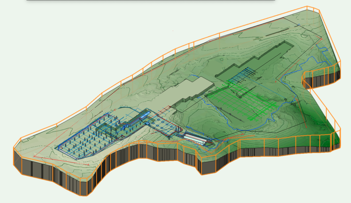
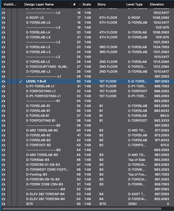
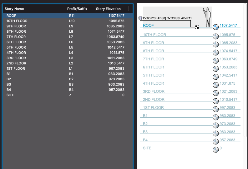
Hi Ashot, I have no issue setting my building and site model to the correct z elevation. As you can see, I have a layer set to zero for my site model and all subsequent layers are for the two building on the site. If, you place section line on the same layer you are sectioning. It will reside on that layer and not 0.0 (Z). For instance if I want to section building E level 1, I would draw the Section line on Design Layer "Level 1 D+E". That section line or any other planar Object be created on that layered not and not 0.0 (Z). I, think this works because 2D objects considers all design layers 0.0 even though the actual elevation could be 997.2083. I hope this helps The site model is on the "site" layer

-
STRUCTURAL MEMBER - how to report length of member
Gualterino replied to drelARCH's topic in General Discussion
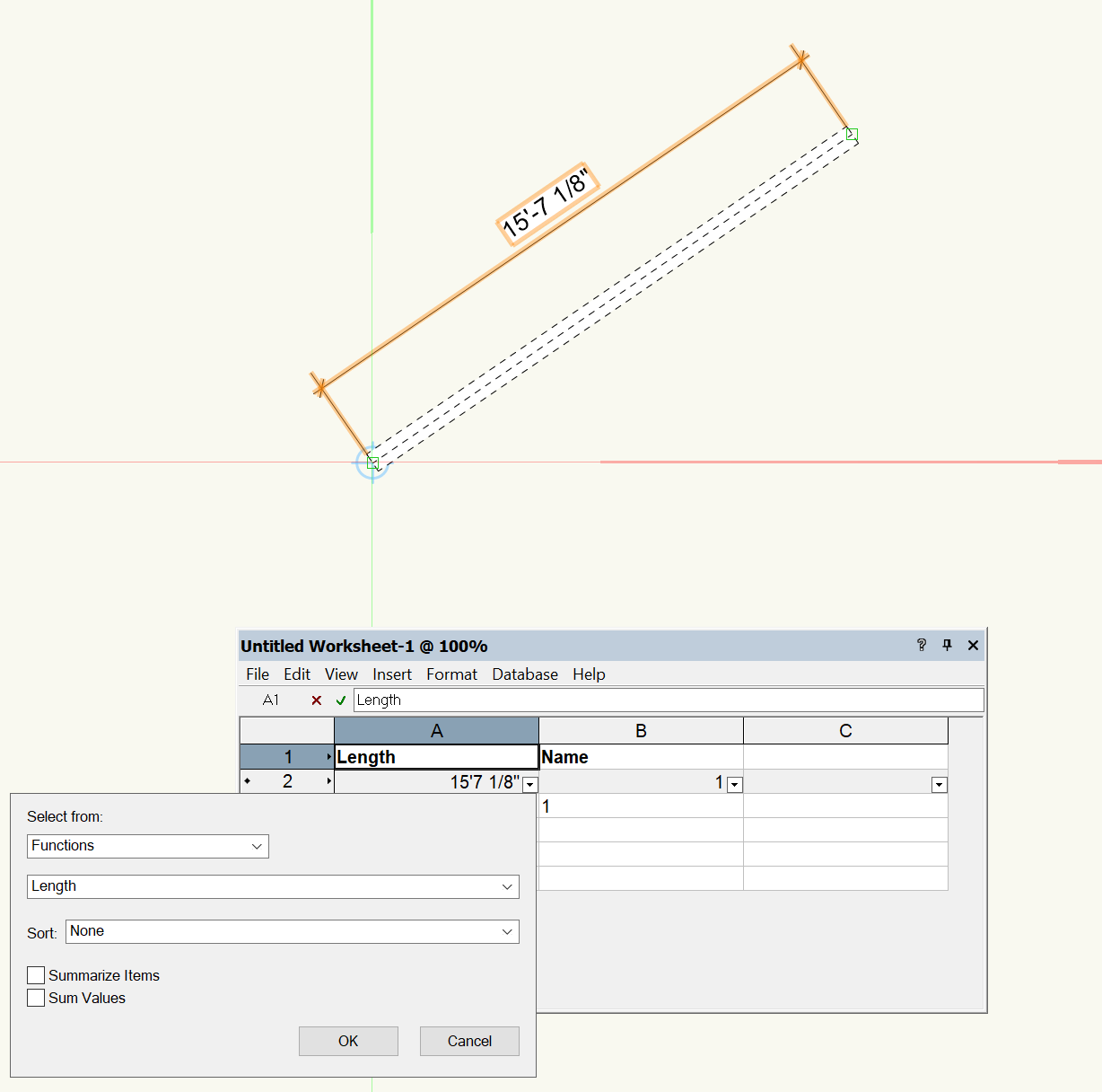
To report the length of your Structural member in your worksheet use "functions" then "length". That should give you what you need.
- 3 replies
-
- 3
-

-
- structural member
- lenght
- (and 1 more)
-
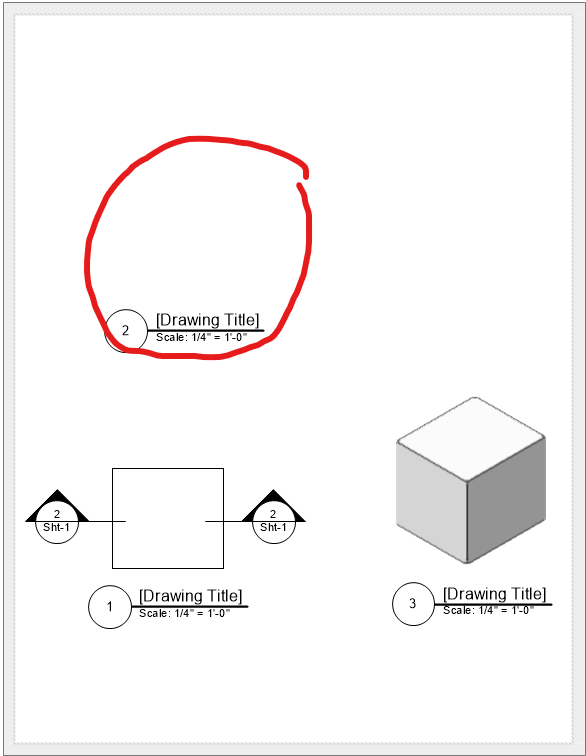
For some reason, when I create a section view they are blank. I tried adjusting the depth to no avail. I tried restarting the computer and Vectorworks, no change. I, even tried a new file with a simple box and as you can see the section is still empty. There must be a setting I need to change but I can't find it. Any help would be appreciated.
-
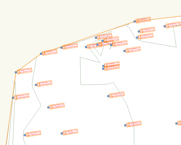
If this is this what you wanted. Keep your site model and stake objects on the same design layer, then set your stake label to coordinates.
-
If you are using Leica ICON, exporting the 3D polygon as a dxf or dwg will be recognized as a surface dtm. I don’t if it’s the same for Topcon
-
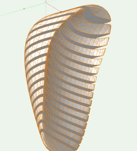
Hi Giulio, The reason why you have those openings instead of a closed solid, is because your mesh is overlapping it's self in the corners. I would suggest breaking it up in two parts; use a a extruded polygon for the top section use subdivision for what's underneath. Then, you can convert the Sub to a mesh and do a solid add with the polygon. From this point everything should subtract as expected.
-
Hi Giulio, Could you post the subdivision, If you don't mind. I would like to see how that happened. Because when you subtract solid you should not have gotten the result shown.
-
Hi Giulio if you to convert the Subdivision to a Mesh first, you should be able to as Hans-Olav stated. That is what I have done here.
-
My issue is that I created a Data tag, to display the size of a concrete beam. The tag was set to show the Major breath and depth. My document units are set to feet but the data tag is displaying everything in millimeters. This is what I used in the Tag "#StructuralMember#.#D#X#StructuralMember#.#B#". How can I get it to display 3' instead of 914.40000?
-
Select both nurbs and convert to mesh, set the fill to solid. Then use the push pull tool to extrude the mesh.