shodkin
-
Posts
15 -
Joined
-
Last visited
-
Hello, I was hoping someone would be able to help me invoke the "Simplify Polys" command on a selected poly using vectorscript? I have a function that draws a very detailed polyline, using a large number of vertices. This function is used to create polylines for a few different applications, some of which require a lot of vertices and others which don't. I currently have to run the script and then go through manually afterwards and use the "Drafting Aids > Simplify Polys" command but I was hoping to be able to write this step into the script, getting the level of detail from a dialog box, somehow? DoMenuTextByName doesn't seem to work when just passed 'Simplify Polys' and there does not appear to be "SimplifyPolys" in the VS Reference Many thanks in advance and sorry if the answer is already out there.
-
Hi, Thanks for all the responses. Sorry it's taken a while to get around to this but I thought I'd post the solution I came up with incase it is useful to anyone else... I ended up creating a VectorScript to do this, it had the advantage of allowing a lot more control over what is created and how! Plus it can be created to work on multiple lines in one go, rather than having to be manually repeated over and over as well as adding class info to each object automatically as it is created. In addition, the section at the beginning which reads in the path info (number of paths, width of each path etc) can also be read in from a symbol, which avoids having to enter all the information every time... procedure CreatePaths; var counter :integer; pathWidths :Dynarray[] of real; totalNumPaths :integer; pathBoundaries :Dynarray[] of handle; paths :Dynarray[] of handle; pathsCenterline :Dynarray[] of handle; lineAStart, lineAEnd, lineBStart, lineBEnd :vector; totalNumPathBoundaries :integer; pathNumber :integer; default, result :string; tempPathA, tempPathB :handle; tempInteger :integer; tempReal :real; temp :handle; currentCenterline :handle; highwayCenterlines :Dynarray of handle; totalCenterLines, activeCenterline :integer; begin {Check to see if at least one HIGHWAY centerline has been selected} if (FSActLayer <> Nil) then begin {Centerlines of selected HIGHWAYS are counted and array populated to hold them} totalCenterlines:=count(sel); Allocate highwayCenterlines[1..totalCenterlines]; activeCenterline:=1; {HIGHWAYS are added to array} while (activeCenterline <= totalCenterlines) do begin highwayCenterlines[activeCenterline]:= FSActLayer; SetName(highwayCenterlines[activeCenterline], Concat('Highway-Centerline-',Num2StrF(activeCenterline))); SetDSelect(FSActLayer); activeCenterline := activeCenterline + 1; end; {all HIGHWAY centerlines are now stored in "highwayCenterlines[]"} {Ask user for total number of PATHS to be created along the HIGHWAY} default :=''; result := StrDialog('Enter Number of Paths...', default); totalNumPaths := Str2Num(result); counter :=1; {Define an array to store the pathWidths as reals, total highway width is calculated and stored in last element (totalNumPaths+1)} Allocate pathWidths[1..totalNumPaths+1]; Allocate paths[1..totalNumPaths]; Allocate pathsCenterline[1..totalNumPaths]; {Asks the user to input the widths of the PATHS and stores them from left to right in the direction of the highway path} while (counter <= totalNumPaths) do begin {Input path width is stored in pathsWidth array} result := StrDialog(Concat('Enter width of Path ', Num2StrF(counter)), default); pathWidths[counter] := Str2Num(result); {total Highway width is updated and stored at end of array} pathWidths[totalNumPaths+1] := pathWidths[totalNumPaths+1] + pathWidths[counter]; counter := counter + 1; end; {all path widths are now stored in the pathWidths array with the total highway width stored at the end of array in element "totalNumPaths+1"} {populates the path boundaries with the centerline and outer boundaries} {NOTES: element 1 = HIGHWAY centerLine Element 2 = HIGHWAY righthand boundary Element 3 = HIGHWAY lefthand Boundary Element 4 = Final PATH boundary} activeCenterline:=1; while (activeCenterline <= totalCenterlines) do begin {Create an array to hold the PATH boundary lines, the 4 additional elements are required to store the final path boundaries and to store the centerline and boundaries for the HIGHWAY} totalNumPathBoundaries := totalNumPaths + 4; Allocate pathBoundaries[1..totalNumPathBoundaries]; {Creates the HIGHWAY centerline} pathBoundaries[1] := highwayCenterlines[activeCenterline]; SetName(pathBoundaries[1],Concat('boundry','centerline')); SetClass(pathBoundaries[1], 'Highway-Centerline'); SetFillColorByClass(pathBoundaries[1]); SetLWByClass(pathBoundaries[1]); SetLSByClass(pathBoundaries[1]); {creates the HIGHWAY top boundary and sets its name and class information} pathBoundaries[2] := OffsetPolyN(pathBoundaries[1], pathWidths[totalNumPaths+1]/2, false); SetName(pathBoundaries[2],Concat('boundry','top')); SetClass(pathBoundaries[2], 'Highway-Boundary'); SetFillColorByClass(pathBoundaries[2]); SetLWByClass(pathBoundaries[2]); SetLSByClass(pathBoundaries[2]); {creates the HIGHWAY bottom boundary and sets its name and class information} pathBoundaries[3] := OffsetPolyN(pathBoundaries[1], -pathWidths[totalNumPaths+1]/2, false); SetName(pathBoundaries[3],Concat('boundry','bottom')); SetClass(pathBoundaries[3], 'Highway-Boundary'); SetFillColorByClass(pathBoundaries[3]); SetLWByClass(pathBoundaries[3]); SetLSByClass(pathBoundaries[3]); {creates the final PATH boundary and sets its name and class information} pathBoundaries[4] := CreateDuplicateObject(pathBoundaries[3], NIL); SetName(pathBoundaries[4],Concat('boundry',Num2StrF(4))); SetClass(pathBoundaries[4], 'Path-Boundary'); SetFillColorByClass(pathBoundaries[4]); SetLWByClass(pathBoundaries[4]); SetLSByClass(pathBoundaries[4]); {increases the counter to the number of the next PATH to be created and begins creating the remaining PATHS} counter := 5; pathNumber :=1; while (counter <= totalNumPathBoundaries) do begin {Tempory PATH boundires are created to allow composed objects to be created later while retaining the original PATH boundaries} tempPathA := CreateDuplicateObject(pathBoundaries[counter-1], NIL); pathBoundaries[counter]:= OffsetPolyN(pathBoundaries[counter-1], pathWidths[pathNumber], false); {Classes and names are set for the PATH boundaries} SetClass(pathBoundaries[counter], 'Path-Boundary'); SetFillColorByClass(pathBoundaries[counter]); SetLWByClass(pathBoundaries[counter]); SetLSByClass(pathBoundaries[counter]); SetName(pathBoundaries[counter],Concat('boundry',Num2StrF(counter))); tempPathB := CreateDuplicateObject(pathBoundaries[counter], NIL); SetName(tempPathB, 'TempB'); {Retrieves the start and end points of the 2 temporary boundary paths and stores them in "lineStart" } GetPolylineVertex(tempPathA, 1, lineAStart.x, lineAStart.y, tempInteger, tempReal); GetPolylineVertex(tempPathA, getVertNum(tempPathA), lineAEnd.x, lineAEnd.y, tempInteger, tempReal); GetPolylineVertex(tempPathB, 1, lineBStart.x, lineBStart.y, tempInteger, tempReal); GetPolylineVertex(tempPathB, getVertNum(tempPathB), lineBEnd.x, lineBEnd.y, tempInteger, tempReal); {Deselects all objects on in the Vectorworks document} DSelectAll; {Draws 2 lines which links the 2 PATH boundaries to create 4 connected lines and makes sure they are selected in the document} moveTo(lineAStart.x, lineAStart.y); lineTo(lineBStart.x, lineBStart.y); setSelect(LNewObj); moveTo(lineBEnd.x, lineBEnd.y); lineTo(lineAEnd.x, lineAEnd.y); setSelect(LNewObj); {selects the 2 PATH boundaries so that both PATH boundaries and the 2 end lines are now selected in the document} setSelect(tempPathA); setSelect(tempPathB); {Composes the selected lines, which should be the 2 boundary lines and the 2 end lines, into a single polygon} DoMenuTextByName('Compose',0); {Assigns the newly created polygon to the "Path-Section" class} setSelect(LNewObj); temp := LNewObj; SetClass(FSActLayer, 'Path-Section'); SetFillColorByClass(FSActLayer); SetLWByClass(FSActLayer); SetLSByClass(FSActLayer); paths[pathNumber] := FSActLayer; {Creates a new centerline for the PATH section and adds it to the centerline array} pathsCenterline[pathNumber] := OffsetPolyN(tempPathA, (pathWidths[pathNumber]/2), false); SetClass(pathsCenterline[pathNumber], 'Path-Centerline'); counter := counter +1; pathNumber := pathNumber + 1; end; activeCenterline := activeCenterline +1; end end else {Script had been run with no objects selected} begin AlrtDialog('Please select a centerline!'); end; end; {Run the program} RUN(CreatePaths); Hope its of use to someone, and if anyone ends up making it a bit shorter/simpler... please repost! Many thanks
-
Hello, I was wondering if it was possible to get any more advanced user input while running a script? As a basic example: something similar to the scale tool which allows users to select a distance, and then another distance, and then performs an operation As a more complex example: something that would allow a user to place a symbol in the document which they would like to duplicate along a path, then draw a polyline and, as the user is drawing the polyline, calculating a bounding box for the symbol and have it "traced" along the polyline that is being drawn to give the user a real time preview of what will be drawn when the operation is completed? Similar to the "Duplicate Along Path" preview button but in real time with the user able to change the path object and instantly see the result? I thought Id ask this in the Vectorscript section due to the possibility of having the user using Vectorworks functions/tools to draw a polyline with the mouse for example, but any suggestions for Python also very welcome! Many thanks
-
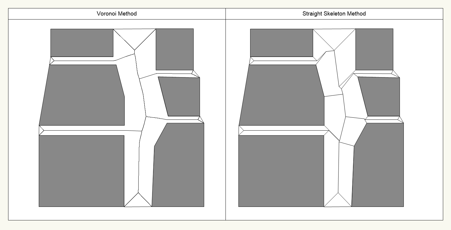
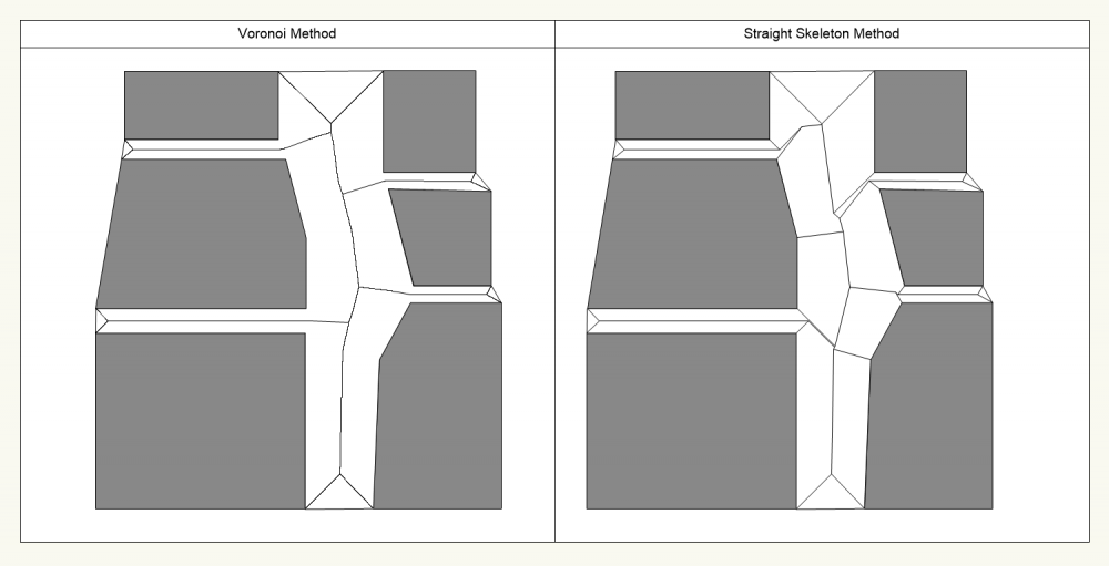
Hi, Thanks for the responses. I ended up approaching this using Python rather than VectorScript due to the number of available libraries out there for Python. I found a number of the many approaches I found it seemed that the Voronoi method was one the most accurate and the Straight Skeleton method was one of the fastest. They both have their limitations and, for my uses, require some cleaning up once they have run, but they are a good starting point. I have attached the resulting image and code for each method below, should anyone else wish to implement something similar... Voronoi Method: " import vs from shapely.geometry import Polygon from ladybug_geometry_polyskel.polyskel import skeleton_as_edge_list def Create_Center_Polys_Skel(p): #create a blank array to hold the of the shape we wish to # find the centerline for list = [] #Loop through each vertex in the shape and add its coordinates # to the list for currentPoint in range(vs.GetVertNum(p)): x1, y1 = vs.GetPolyPt(p, currentPoint+1) list.append([x1, y1]) #Create a "shapely" object of polygon from the vaules in the # list we have just generated polygon = Polygon(list) #Run the "Labybug PolySkel" function on that polygon and assign # the return vaule, to "skelcenterline" skelcenterline = skeleton_as_edge_list(list) #Loop through each created vertex in "skelcenterline" and extract # the start coordinates and end coordinates of each line that was # created. When the start and end coordinates have been separated # move the Vectorworks "cursor" to the start point of the line, # and draw a line terminating at the end point for m in skelcenterline: startcord, endcord = m startx, starty = startcord endx, endy = endcord vs.MoveTo(startx, starty) vs.LineTo(endx, endy) #Run the menu command "compose" on all created objects to try and # consolidate them into as few polylines as possible for manipulation # later vs.DoMenuTextByName('Compose',0); #Set "selectedPoly" to be the currently selected Vectorworks polygon selectedPoly = vs.FSActLayer() #Run "Create_Center_Polys_Skel" passing it the polygon we just created # from the selected poly in Vectorworks Create_Center_Polys_Skel(selectedPoly) " Straight Skeleton Method: " import vs from shapely.geometry import Polygon from ladybug_geometry_polyskel.polyskel import skeleton_as_edge_list def Create_Center_Polys_Skel(p): #create a blank array to hold the of the shape we wish to # find the centreline for list = [] #Loop through each vertex in the shape and add its coordinates # to the list for currentPoint in range(vs.GetVertNum(p)): x1, y1 = vs.GetPolyPt(p, currentPoint+1) list.append([x1, y1]) #Create a "shapely" object of polygon from the values in the # list we have just generated polygon = Polygon(list) #Run the "Labybug PolySkel" function on that polygon and assign # the return value, to "skelcenterline" skelcenterline = skeleton_as_edge_list(list) #Loop through each created vertex in "skelcenterline" and extract # the start coordinates and end coordinates of each line that was # created. When the start and end coordinates have been separated # move the Vectorworks "cursor" to the start point of the line, # and draw a line terminating at the end point for m in skelcenterline: startcord, endcord = m startx, starty = startcord endx, endy = endcord vs.MoveTo(startx, starty) vs.LineTo(endx, endy) #Run the menu command "compose" on all created objects to try and # consolidate them into as few polylines as possible for manipulation # later vs.DoMenuTextByName('Compose',0); #Set "selectedPoly" to be the currently selected Vectorworks polygon selectedPoly = vs.FSActLayer() #Run "Create_Center_Polys_Skel" passing it the polygon we just created # from the selected poly in Vectorworks Create_Center_Polys_Skel(selectedPoly) "
-
Thanks, That's kind of what I thought... Cant it be acomplished with the Marionette commands and if not do you know if there are any good scripting tutorials available?
-
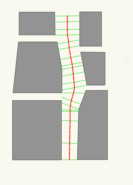
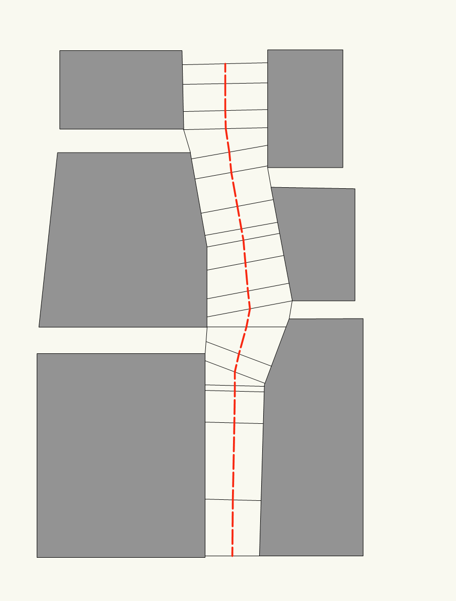
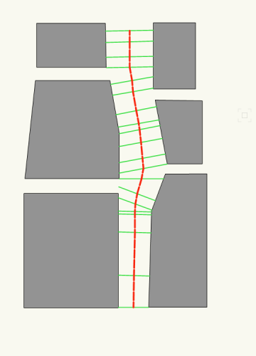
Hi, Thanks a lot for your quick response...! I was looking for a way to create the line in red, from the lines in green below? Compose would only seem to "join" connected lines... the way I would normally go about doing this would be to just manually draw a polyline through all these lines using "snap to midpoint" however I was hoping there was an easier way? Many thanks
-
Hello, I was hoping someone might be able to help? I am looking for a way to draw a polyline which links the midpoints of a group of selected lines? Specifically, I am trying to draw a polyline along the center of a road. I have a number of lines which run perpendicular to the path of the road and the mid point of these lines defines the middle of the road. So I would like to be able to select all these perpendicular lines and automatically draw a polyline which passes through all these points? Creating the red center line shown in the attachment (sorry for the cartoon-ish appearance!) I say automatically as some of these paths will potentially be Km long and contain hundreds of lines... Many thanks

-
Hi Benson, Thanks for this, its a lot closer to the elegant solution I was looking for. Many thanks
-
Hi Pat, thanks a lot. I ended up creating my own "profiles" using lines (1x line 2.5m + 1x line 1.5m) next to each other, then extruding them along the path of the center line I created, converting the "extrude along path" object to a NURBS group and then each NURBS inside the group back into a polygon and using add surface... Converting them to a NURBS first (rather that straight to polygons) meant that I could go into the group and select each "path way" and "road way" and individually to add the areas in one go rather than having to try and select all the associated polygons in one area.
-
Hello, I am trying to import a dwg however the fill of the objects is not coming across properly... When I import the objects (which are represented in AutoCAD as a polyline and a hatch) come across as a polyline which has the same fill associate with it as the original hatch, however in AutoCAD these hatches are derived from the class and once they are imported to Vectorworks they are simply solid (static, not based on the class) where as the line style and colour continue to be based on the original class... Is there an import option somewhere I've missed?
-
Hello, Firstly apologies if this question has been asked before but I cant find a solution anywhere... I am trying to create a a 2D plan of a fairly simple road network for a temporary event. I have a base map showing the positions of the buildings, I have added perpendicular lines in between the buildings to get the centre points of the road and I can then draw a polyline through those points to give me a line going down the center of the road. I know that, centred on that line, I need enough space for a 2.5m path for vehicles and 1.5m path for pedestrians, so a 4m wide area in total. What I would like to be able to do is something similar to "Extrude along path" but for a polygon? So I can create 2 polygons, one 2.5m wide and another 1.5m wide, next to each other on the center line I have drawn. I know I can achieve something similar with the "Double Line Polygon Tool" (draw a 4m wide polygon along the centre line, then a 2.5m wide polygon along one edge and then a 1.5m wide polygon along the other edge and delete the original 4m wide polygon leaving the remaining 2.5m and 1.5m polygons) but I was hoping for a way of firstly, drawing both polygons at once, and secondly, being able to edit the path of the resulting polygons as you can when extruding an object along a path? instead of having to move the individual points that make up the resulting polygon. That way I can easily tweek the polygon while maintaining the width? I think what I'm looking for would be something like "Extend along Path"? But I cant see anything like it? I'm using VW2019
-
Assign Default values to the "User Field 1, 2 , 3 etc"
shodkin replied to shodkin's topic in Entertainment
Perfect Klinzey, thank you! -
Assign Default values to the "User Field 1, 2 , 3 etc"
shodkin replied to shodkin's topic in Entertainment
2019 Spotlight SP4 -
Assign Default values to the "User Field 1, 2 , 3 etc"
shodkin replied to shodkin's topic in Entertainment
The fixture type, so an ETC Source 4 19 Degree would be 10201, a 26 degree would be 10202, a 36 would be 10203 etc -
Hi Is it possible to assign a default value to a User Field variable, so that every time an Lighting Device is inserted the User Field is pre-populated with a certain value, in the same way that weight, wattage etc are? We use a database system to manage our internal stock levels and it would be really handy if we could generate a report for each event which, along with the lighting devices name etc, also outputs our asset number for the devices we are using?