


Conrad Preen
-
Posts
1,023 -
Joined
-
Last visited
Content Type
Profiles
Forums
Events
Articles
Marionette
Store
Everything posted by Conrad Preen
-
Haven't tried this, but maybe if you make your numbering rule in text in a text editor you could introduce a line break... :-J A horrible hack but it might work... Conrad
-
@Edward Carlson thanks for reaching out - we will take a look at this. Conrad
-
@ryanwwRegarding break in/out, we are at that time of year when a lot of the "asks" we hear are stuff that is developed but not yet released. So I think as time goes on we will converge on something closer to what you want. I agree that more training materials are needed. But that isn't really my department. Tech Support need to hear this from YOU. About this... that hand-waving phrase "some modifications to work with ConnectCAD" hides a lot of issues. And that's what I'm trying to get at here. We can create a circuiting view from a connectivity schematic plus a network of cable paths. All the information is there. You can't automatically create a schematic from the circuiting you have shown above because the layout of devices and circuits has to be entered by the designer. It's good that we are having this discussion but we have to get a bi more specific.
-
@trevorgooch Just to read back then - the missing part for you is to specify in runs comprising several physical cables in series where the joins go?
-
Cable Name's position in 2D view 'breaks' when reshaping connection
Conrad Preen replied to Sean Emer's topic in ConnectCAD
Hi Sean, Please say which version of Vectorworks and if possible add a screen shot or even better a file and a brief description of how to reproduce the problem. I'm sure it will be easy to help you 🙂 Conrad- 1 reply
-
- 2
-

-
Just tried renumbering 2000 sockets starting from 300. Screenshot from VW2022 Use the Custom option to enter an arbitrary start number. Conrad

-
Hi Ryan Actually we are pretty close now to what you are looking for. Our Cable Route Planning tools already allow you to design the physical paths of cables and assign schematic circuits to them. And the cabling diagram you show will be implemented as a view generated from the path model and the schematic. I think the confusion arises from the fact that Spotlight has its own Cable Tools aimed at the needs of touring shows rather than permanent installs. ConnectCAD has the tools to support permanent installs. We have done our best to integrate our workflow with Spotlight - for example we share the Cable Path object. I agree 100% that 2D is the way most engineering is done. That's why ConnectCAD has its own Cable Routing tool that you use mostly in 2D Top/Plan view to link up the places where cables are delivered (Drop Points). You basically get the 3D for the price of 2D. Linking up the connectivity designed on the schematic with the actual physical route of the cables is the challenge. Somehow you have to put the data in. A cabling diagram on its own doesn't "know" enough. Just having an arrow pointing to "5TH FLOOR AV RACKS" doesn't tell the software how the cables will get there or even what an AV rack is! That's the challenge we are addressing. As far as multi-cables go, you can define your own cable types RYAN1, RYAN2 etc. to mean whatever you like so you could always use that to indicate a multi. Thanks for the input and please do give the ConnectCAD Cable Path Planning tools a try. There is more help than you might think in the Vectorworks online help. I've been trying to get more how-to info included there. Best Conrad
-
You are reading my mind it seems... C
-
This forum isn't just about the details - it's also a place for discussing broader philosophy. So I just want to share some thinking about how we model connected stuff. We have kind of triangle involved where knowing any two of the sides implies the third side. SCHEMATIC CONNECTIVITY CABLE PATHS PHYSICAL CABLES In ConnectCAD we use the equation CONNECTIVITY + PATHS = CABLES. The actual physical cable has a path and connects two things so you might ask "why not just draw the physical cables directly on floor plans?" The problem is that is it really hard to understand the the signal flow in that kind of drawing for anything but the simplest of systems. So that's why we design connectivity separately from the physical cabling. Physical cables mostly share a limited set of paths - ducts and conduits cost money and space so it makes sense that cables going to roughly the same place should follow the same routes. This why in ConnectCAD we design cable paths and infer the physical cabling. We could easily generate the physical cables as drawing objects using an algorithm. The reverse, generating a connectivity schematic from physical cables is not nearly as simple - imagine the complex rules needed to lay out a meaningful schematic... So that's why we do things the way we do. But there are times when designers want to specify the actual physical cabling in detail. Maybe the cables come in standard lengths and we need the junctions to be at specific locations? Maybe we will run several schematic circuits thru a single multi-core? ConnectCAD already provides a workflow for this. You can draw the physical cabling using the Spotlight Cable tool (following paths if needed) and assign Cable Run IDs to each complete route. On ConnectCAD schematics you can then assign Circuits to use a particular cable run by setting the Circuit.Cable parameter to the Cable Run ID. This overrides the automatic assignment of circuits to cable paths and the length is taken from the Cable(s). I guess the issue here is that our support for physical cables is very much a manual workflow. And that's why I want to open up the discussion to you. I would like to hear your thoughts. Conrad
-
How to lay out "adapters" (devices / equipment items)
Conrad Preen replied to Mark Aceto's topic in ConnectCAD
@Nikolay Zhelyazkov Mark is potentially chaining adapters here... just for us to consider... -
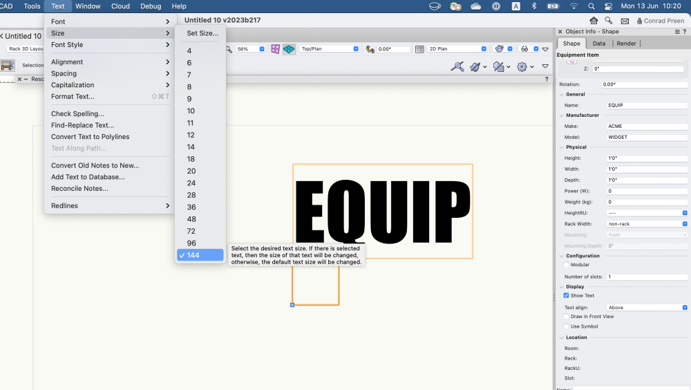
@Mark AcetoText > Size menu with Equip selected C
-
Hi Mark Wow. I'm having a tricky time matching up what you're doing with what Cable Path Planning was designed to do. But all good insights. So here you have two separate networks of cable paths (signal and power) and you want to show the TV connecting to both. For the particular job you describe the electrical network is already in place - right? So you aren't going to be planning that at all - correct? So all you actually need to do is draw a wiggly line from the TV to the power outlet just in case some installer dude is soooo dumb that he doesn't know to plug in a power cord. On a theoretical level however you do raise an interesting question. As you point out there are cases where we might connect an equipment item to multiple drop points. I need to think it through and check for unintended consequences but on the face of it that sounds do-able. Thanks for sharing! As far as the size of the TV text is concerned - obviously you can't have larger text AND keep it within the bounds of the object. So what are the options? In the Equipment OIP you can set the text to display above the object and then increase the font size using the Text > Size menu with the object selected. Or you can choose not the display the text at all and use a Data Tag linked to the Equipment.Name parameter to display the name in any way you prefer. Hope I've helped out here.
-
Extended number of data elements of circuit graphics
Conrad Preen replied to elc's topic in ConnectCAD
Hi George, Let me just read that back to you to check. You want to be able to display the value of any record field from the source/destination socket or device as part of the arrow circuit label - correct? This doesn't sound unfeasible for a future version but is definitely not possible now. Right now the Circuit can only display its object parameters and any records attached to it or combinations thereof. Some device and socket params are copied into circuit params at the moment for various reasons but I would say it's always best to go back to the source of the data. Thanks for reaching out. Conrad -
Import layers, classes, etc from ConnectCAD
Conrad Preen replied to Mark Aceto's topic in ConnectCAD
Hi Mark Generally speaking ConnectCAD automatically imports any resources it needs so you can use all the tools in any file. One thing to be aware of is that symbols used in schematic elements are scaled to match the current snap grid size. The purpose of this is to allow you to draw schematics using any layer scale, not just 1:1. In the templates the grid is set to 1/4" or 4mm in metric. So if you import resources from the ConnectCAD template they will look good at 1:1 scale with the standard snap grid. That's basically what you need to look out for. Conrad -
Here is Niko's Data Manager video tells you how to set up a data mapping so that your custom record is added to every new Device. You can also see examples of this in the ConnectCAD templates. ConnectCAD with Data Manager.mp4
-
@Thomas_Ok, we located this and I'm posting it to the Did You Know thread which is at least at the top of the list.
-
Well we do a lot of trying to guess your intentions in this command... and on this occasion it looks like we did not succeed. You see, some people want the existing numeric suffix retained and others want it replaced. In this case the selection set does not have a consistent numeric suffix so one might reasonably assume that the numbers are part of the name. If you can think of a way to figure out the users intention let me know 🙂 And at the end of the day if the command helps out 95% of time I think it's OK and we should not add extra complications. Best Conrad
-
@Thomas_ One of my peeves at this forum is how hard it is to locate answers that are relevant to your question. Sorry about this but I have a pressing deadline and try as I might I can't find it right now. It is there but I haven't the time to search it out.
-
Removing "CTP" from connection panels?
Conrad Preen replied to livespace josha's topic in ConnectCAD
Well these are certainly things we discuss and think about. The question comes down to us wanting some devices to have additional special behaviours and how to make the device "understand" that. Naming conventions are one way to do this. I certainly have in mind to handle this a different way but I need to be sure we actually solve the problem and don't just move it around. -
Dear @Thomas_ You can attach any record to a socket or a device using the normal Vectorworks procedure. Please check the help for details about creating record formats and attaching to objects. You can also place additional text inside your socket and link it to the attached record fields to display the value. I think there's an artcile on this in the Did You Know section. Finally all this can be automated see Niko's video on the subject. Best Conrad
-
@pcoleman @cessnaflyer and everyone generally - if you are having a problem you can always call Tech Support and they will guide you through diagnosing it. By all means feel free to report problems here too. But, we can get to a solution a lot quicker if you supply some basic information: What's the problem. What you were doing when the problem happened What you were expecting to happen What actually happened Screen recordings / screen shots are useful A sample file and steps to reproduce the problem are great Information about your system Mac / Win, Vectorworks version etc. Being able to reproduce the problem is key to resolving it. Best Conrad
-
@TomBass The device database is a tab-separated text file that you can open and edit in a spreadsheet. You will have to get your head around the format. If you create a device in the Device Builder and then look in the folder ConnectCAD_Data in your user path, you will find the file ConnectCAD Devices DB.txt. If you enter data in the same format it will be accessible to the Device Builder and Create Devices from Worksheet. Obviously we can't validate this data so you may break stuff. That is price you have to pay. Regarding user contributions to the database, I very much appreciate your offer. We used to do it that way. Unfortunately not everyone was very careful about the data they entered so it became a bit of a mess. For now we have brought this in-house but of course I realise that we are in a fast-moving industry and we need to keep up. I have some ideas to fix this but they are still under wraps. Conrad
-
Spotlight Numbering Not Working For Connections Bewteen Design Layers
Conrad Preen replied to sbecraft's topic in ConnectCAD
@sbecraft Well, Spotlight Numbering was not designed to handle the particular case. It is a limitation of Spotlight. The destination end of a cross-layer circuit is a proxy object, not the actual circuit object itself. ConnectCAD's own numbering command takes care of this 'cos we know about it. So why not use that instead? Conrad -
@CharlesD Again please be patient - we are on the same page believe me!
-
Why no ability to delete default signals etc?
Conrad Preen replied to CharlesD's topic in ConnectCAD
Dear @CharlesD We are in the process of reviewing and revising the signals, connectors and device data. These are all related so it has to be done in one go. The question of turning off default content has already been discussed at length in another thread. It would have to be all or nothing and I believe would create its own swathe of problems when people who have gone their own way want to work together again. It's that time of year when you all start to bring up matters that we are already tackling but we can't tell you about yet. Please be patient, we are constantly working to improve ConnectCAD. Kind regards Conrad

