Conrad Preen
-
Posts
1,023 -
Joined
-
Last visited
Content Type
Profiles
Forums
Events
Articles
Marionette
Store
Everything posted by Conrad Preen
-
Hi Jonny Regarding the "Renumber Device deletes the name" bug please me the file as a private message here on the forum. Also tell me the steps I need to take to reproduce. Thanks very much for reporting. We'll get that fixed right away. With the Renumber commands Start field I will add a 'Custom...' choice to the popup so you can type in any value and it will be added to the available choices for the session. Spotlight Numbering can be used but it is arcane. You need to append the number to both the Device.Name and Device.Tag parameters. Remember the Name is shown in lists, the Tag is shown on the drawing. That's to let you save drawing space by abbreviating and leveraging the context. Multi-Connect is very simplistic in the way it works and very predictable: it connects outputs on the right-hand-side of devices to horizontally opposite inputs on the left-hand side of other devices. I don't think there's a good way to make it connect across layers. Conrad
-
Hi Daniel, Well I am pondering that also. Basically the difference is that if it was a text field it would have to be validated as a number and an alert displayed if it wasn't. Pretty standard stuff. Ideally I'd like both: an editable popup to quickly select "normal" values but be able to type in if it's something extreme, and then I woke up 🤣 Conrad
-
As Daniel says the Spotlight Numbering tool is another way. It let's you do incremental numbering of any parameter which is more power than you need. I'm just wondering if I make the popup go from 1 thru 512 if that will sort out the problem for you. It's only the start of the number series - if you begin at 256 the devices get numbered 256, 257, 258 etc. Conrad
-
Hi JonnyAVC, Sorry it took me a while to get to this. My guess is that you are talking about the Renumber Devices menu command? So we're talking about the Start: popup which has values 1 thru 256. How large a number do you need? The other thing about the device Name occasionally being replaced instead if the number being appended sounds like a bug. Next time this happens could you save the file and make a note of exactly what you just did and send it all to me? If we can reproduce this it should be easy to fix. Thanks Conrad
-
Managing Cable Type Labels and Editing 3d Device Models
Conrad Preen replied to Harrison_'s topic in ConnectCAD
Hi Harrison, Regarding point 1) we're talking about the "14/2" label I guess? Two ways to fix this: a) Select the circuit. You'll see a little blue square in the middle of the "14/2" label. That's a control handle - grab that with the mouse and pull it to where you want it to go. b) But what you really want is to make it the same as the circuits below - right? Select the circuit you want to change (the top one), then pick the ReRoute tool in the Schematics toolset. Now move the cursor over the circuit below and it will highlight red. Click and the label will move to match. Point 2). Certainly possible - we have some ready-made content in Vectorworks from the Spotlight side of things. Moving forward we will be looking at providing more in the future. Right now it's always possible to import 3D model from manufacturers website if they provide them. But by far the simplest is to clip the faceplate off the web, double click your equipment item to enter the objects group, and paste your graphic in there, adjust size to fit, done!. Do all that and you'll have your ankles wet 😄 Conrad -
Hi Kevin, Thanks for your comments. Regarding custom fields: If you save the document as a template the worksheet customizations are saved too. The menu command Current Layer Device Report simply opens the worksheet with that name and updates it. It first looks for the worksheet named Current Layer Device Report in the template and if it doesn't find it then it will import the worksheet from default content. So you only have to add the columns once. No. 'dev_rec' has one purpose in life - to take values from Device fields and make them visible in the device title symbol as linked text. Are you looking for a way to set the default value of user device fields. We have considered this. Device Builder is already a huge dialog and I do wonder where we would fit all this. It's better than it was - previously you had to re-create your custom fields with every upgrade. Now you just have to copy the CustomParams.txt file to your new installation and your done. You can change the display name of custom fields to suit your wishes. Only the universal names are user1, user2 etc. Hope that helps. Conrad
-
Hi Matt Please submit this as a bug (with example document). Maybe we can do something to help. Conrad
-
But I think you are right about the documentation - I'm checking on that. Thanks for posting this!
-
Hi, That because it got simpler. Use the Backspace key to undo point just like the polyline tool. Conrad
-
Devices Disappearing when Opening 2019 ConnectCAD drawings in VW 2020
Conrad Preen replied to tekbench's topic in ConnectCAD
Hey Kelly Thanks for the update. Good to know the system is working. Conrad -
Devices Disappearing when Opening 2019 ConnectCAD drawings in VW 2020
Conrad Preen replied to tekbench's topic in ConnectCAD
Here on the forum it will be quite difficult to resolve this. This sounds like you should call Vectorworks Support and get them to have a look. -
Devices Disappearing when Opening 2019 ConnectCAD drawings in VW 2020
Conrad Preen replied to tekbench's topic in ConnectCAD
Hi Kelly This looks like an old workspace of yours. Have you tried selecting the ConnectCAD workspace supplied with the software? Generally the new SDK-based commands will have different internal IDs from the old Vectorscript. So, if you want to customise the workspace better start again from a copy of the standard one. Let me know if that fixes it. Conrad -
Hi Aruk That's a Vectorworks thing. No duplicate names allowed. At least the message tells you that it's a Symbol Definition you need to go looking for. Things are improving! Conrad
-
Adjusting Rack Elevation text size and position
Conrad Preen replied to jsivonen's topic in ConnectCAD
Really? It should do. Could you buzz me over the file so I can take a look? Conrad -
Adjusting Rack Elevation text size and position
Conrad Preen replied to jsivonen's topic in ConnectCAD
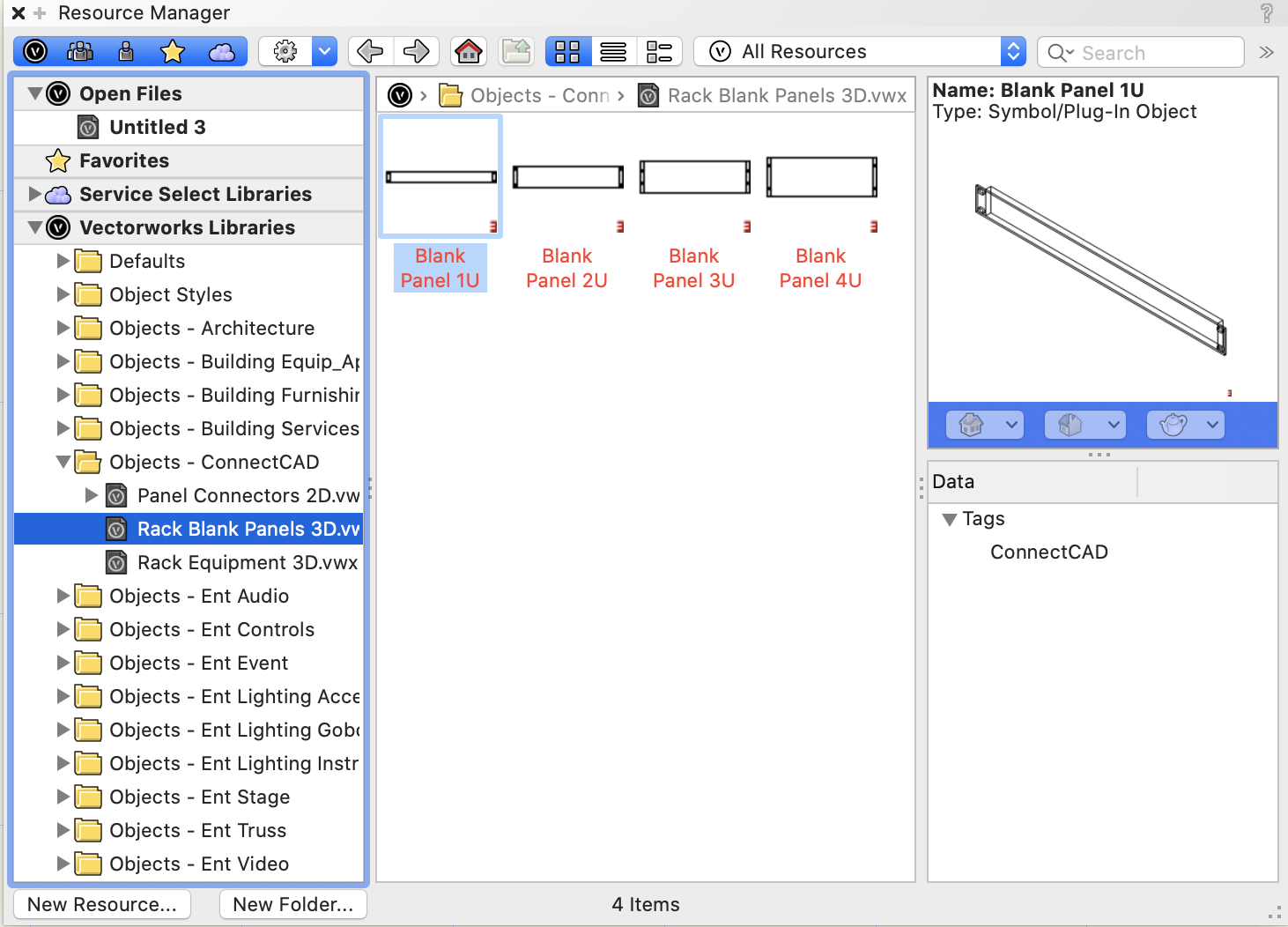
Hi @jsivonen, Not gone - just re-located. Look for these in the Resource Manager. Select your equipment and use the Text > Size menu to set the size lower. You'll have to set a very low size to see a difference because the object automatically scales text down to fit. But there are limits - if you have an Equipment like this AVERYVERYLONGNAME THEWIDGETCOMPANY BESTWIDGETEVERMADE No amount of fiddling with the font size will get you a good-looking readable result. You might consider using shorter words... Conrad
-
Hi Noah, You can connect an output to two inputs using two separate circuits. Of course it makes sense to just parallel the two inputs at the destination end. If your installers can't understand what they should do, I guess you could make the amp input 1 an IO type socket and run a local circuit from that to input 2. Would that fix it? Conrad
-
Hi Thomas, Projectors on your schematic are Device objects. When you have more than one Device with the same Name parameter value ConnectCAD assumes that they all refer to the same physical device in the real world. Equipment objects model real-world physical devices. They are to scale, they have dimensions and geometry. And you can use then in your model. To avoid "double objects" with the Video Screen tool uncheck Show Projector in the Video Screen and put a ConnectCAD Equipment object there instead. A rack elevation doesn't have the information needed to automatically create a schematic. That stuff is in your head. Best Conrad
-
No, because it would have to be implemented in several places. Yes, I do want to bring this up to date - editing text files is so 90's.
-
1) Signal and Connector types added to the Did You Know thread - many people ask this. 2) if you modify the device saved with the same make and model it will be overwritten. 3) For now please do a forum post - separate topic. And I'll get another comms channel open for this. Conrad
-
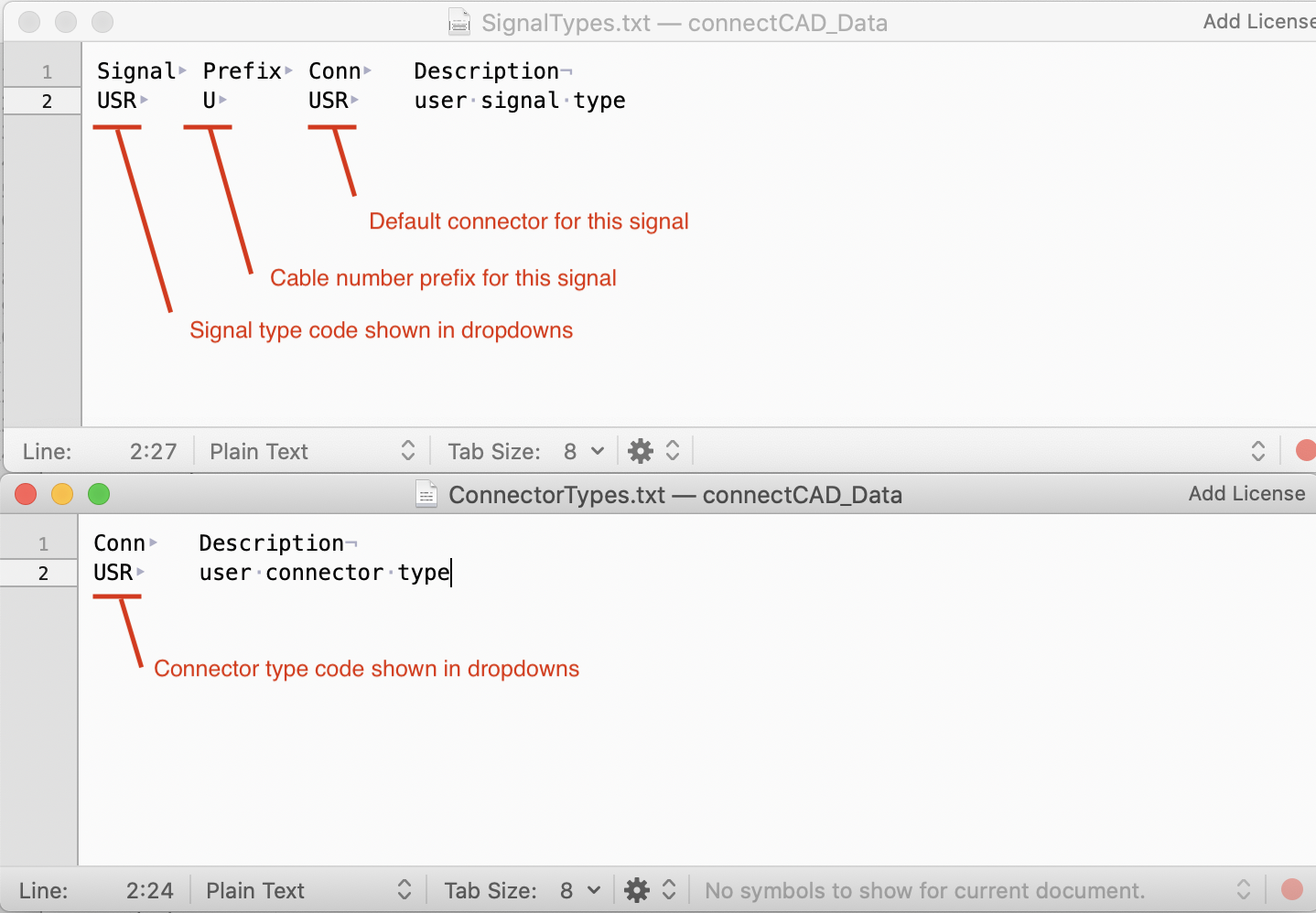
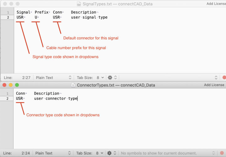
You can add Signal and Connector types. Have a look in your user folder under Plug-ins/connectCAD_Data and you'll find the files SignalTypes.txt. and ConnectorTypes.txt. Questions: - Where's the User Folder? Go to Tools > Options > Vectorworks Preferences and select the UserFolders tab. You'll see where the user folder is in the dialog. - Those files aren't in there - what now? Add the files attached to this post to get you started. - OK got the files - how do I add my signals etc.? Open the files in a text editor. They are simple tab-separated text and the first row is a header showing what the columns do. Here's a picture. Just add as many rows like this as you need. SignalTypes.txt ConnectorTypes.txt
-
At the moment you cannot add this information to the drawing. But it is in our plans 🙂 Conrad
-
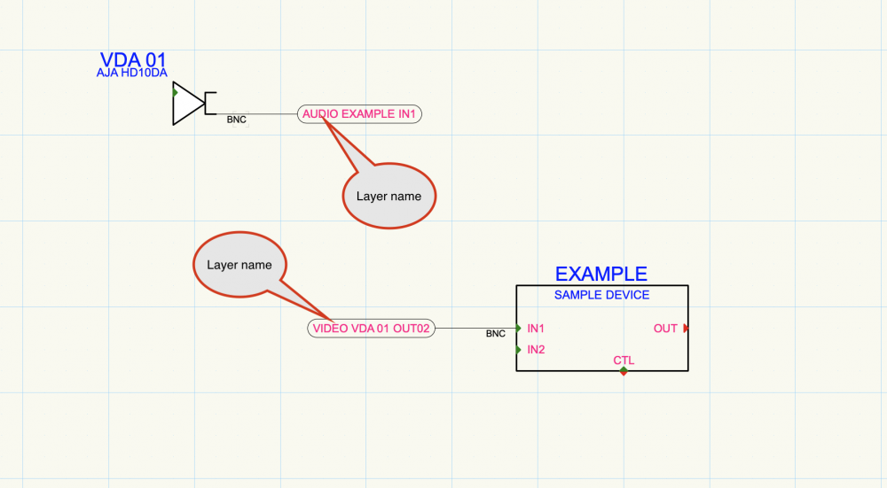
Hang on... layer names are shown for cross-layer arrow connections (see screen shot). Isn't that what you are looking for? C
-
If there is an issue with imperial units that's a bug and we will fix it. I haven't checked right now but I do remember a fix for something like that recently. What still puzzles me is the behavior of your Equipment objects. When I use the standard template but change the units to feet and inches everything works normally. But your file is different and I'd really like to know how it got that way. Conrad
-
What is the best workflow for customized device appearance?
Conrad Preen replied to Thomas Peters's topic in ConnectCAD
Looking good !!! -
Devices Disappearing when Opening 2019 ConnectCAD drawings in VW 2020
Conrad Preen replied to tekbench's topic in ConnectCAD
Ah, now that might explain a lot. But it's the reverse of what you think. I reckon that Migrate may have moved a bunch of old Vectorscript plug-ins into you user path and generally speaking whatever is in the user path overrides the application. The only thing that may be useful to move over from 2019 is the contents of the ConnectCAD_Data folder i.e. any custom signal and connector types. Maybe some symbols from your old template later on. So start with a clean VW2020 install with ConnectCAD activated. First try the basics, New File from template get a feel for the new stuff. Then open one of your 2019 files and see how the update goes. This should all be handled automatically on file open. Anything that doesn't update properly is something we want to have a look at. All the plugins bar a very few are now implemented in SDK and are part of the Vectorworks application so you don't need to every touch them again. That probably clears up the mystery but do let me know how it goes. Conrad