hihosilvey
-
Posts
44 -
Joined
-
Last visited
Content Type
Profiles
Forums
Events
Articles
Marionette
Store
Everything posted by hihosilvey
-
Hello All, I'm trying to produce more quality renders from renderworks but am running into a snag I can't figure out. For some reason I keep getting red walls on my renders and I can't figure out why. The render seems like it's going smoothly until the very end when the artifacts show up. I've attached a screenshot of my viewports. The top left shows a clean render. The others you can see the walls are a red hue. Has anyone else experienced this?
-
Detailed ConnectCAD Training?
hihosilvey posted a question in Wishlist - Feature and Content Requests
Hello, Is there a place where I could find in-depth ConnectCAD training? I've been a CC user since before VW bought it and have always just figured it out after watching the basic videos that are out there. However, the new Cable Routing tools could use some in-depth training. Does the new Spotlight Certification courses cover that? -
Thank you! I knew it was something I was overlooking...
-
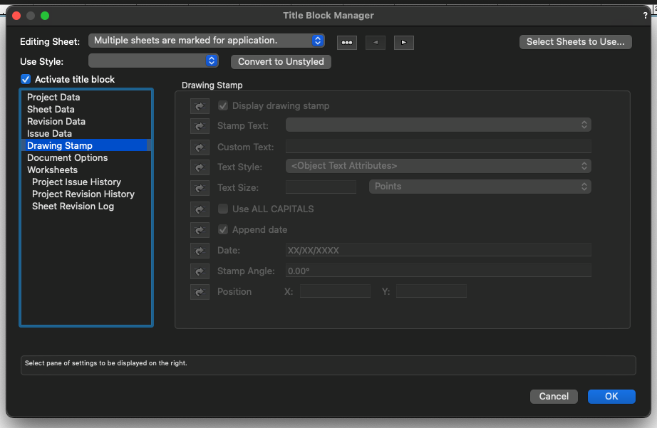
Hello all, For some reason my drawing stamp options are grayed out in the title bock manager, title block border settings, and the drawing stamp options in the OIP. I've double checked the titleblock style settings to make sure the "display drawing stamp" box is checked. I'm stumped... I've attached my file for someone to show me my mistakes. Any help would be appreciated. Thanks! Chad Silvey 2021 Macbook Pro M1 Max MODEL_P220001_HARVESTER KIDS SPACE.vwx
-
Deleting App based connectors and signal types
hihosilvey replied to hihosilvey's topic in ConnectCAD
Thank you all for your ideas and knowledge. I can see where you're headed with this and I don't disagree with standardization, however, I would be in favor of a switch to turn off selectable app data, such as the switch you have to turn off the device builder database in the ConnectCAD settings. Maybe a switch to turn off the connector and signal type data bases as well? The real genesis of where this question arose is that the connector and signal type drop down lists as is can get extremely long and hard to navigate if you've already spent the time building custom connector and signal lists for use in earlier versions. The App Data plus the custom signal lists can be 100 or more connections, some of them duplicated in name only with no customization (ex. class line colors, etc.) I agree with @elc. Maybe there is a way to apply filtering similar to the Make/Model filtering in the device builder? On the flip side, I've been a ConnectCAD user since 2016 and have built, customized, and curated these lists to work with my workflow. To now have to sift through a lot of useless and duplicate data (to me) is frustrating. I remember when I used the app data starting out and it came in handy, but for experienced users things like this are aggravating. One of the things I've loved about ConnectCAD from the beginning is how flexible it is to make it your own. This feels like a little bit of a regression. -
Hello all, In VW 2022, Is there a way to get rid of the default connector and signal types and ONLY show the user folder options? Thanks! Chad Silvey
-
Utiltizing the Custom Parameters in All Layer Cable Report
hihosilvey replied to hihosilvey's topic in ConnectCAD
Thank you both for the info. My gut was telling me the same thing, but I was hoping that was not the case. I am trying to make a modified Cable pull sheet for our installers. One that would tell them the all the info that cable report does along with a reference to the page that cable could be found on. I wanted to add it by socket or device, as with an arrow connection those devices would be on two separate pages. This is something that has become a mandatory item for our drawings and was trying NOT to have to do it all by hand. Now you might be asking....the arrow connection does this already....I would agree. But I was hoping it was possible to get all of that info into one location. -
Hello, I'm trying to add some custom user fields to the All Layer Cable report. I'm wanting to add a some custom data per socket. I've modified the socket user parameters and can see it in the OIP when I am editing a device socket. Is it possible to add that data to the All Layer Cable report? I've tried ='Circuit"."user1" and ='skt_rec."user1" Is this possible to do? I guess I'm a little confused on how the circuit_rec and skt_rec come together to make the Cable reports. Can someone shed some light on this for me? Thanks!
-
Also, I might have missed it, but is there a document that shows the workflow the way ConnectCad was intended to work? A lot of this from me might stem from me just figuring things out on the fly. Thanks!
-
Conrad, Sorry it's taken so long to reply. I really wanted to think about it. The whole reason that we move stuff between layers is that we have to send out paper and pdf docs to our installers. The layers are the way to split out our build in logical sections. The labels on the arrow connections that lead you to the correct page are a crucial component on a printed set. I think it's something that will be around for awhile. It's how the rest of the building industry works (architects, electrical engineers, etc.). We've had to match their workflow. I think we will always have to move things between layers. In my honest opinion, I think you guys are already the best at arrow connections. That is one of the main reasons I switched to ConnectCAD 5 or 6 years ago. Before then we were building manually in autoCAD. To have a program that automatically did that was awesome. My perfect arrow label would be this: 1.Be able to seamlessly change between layers. Learning to do it the other way by building your devices first in my opinion is not as flexible. Clients (mine at least) are notorious for adding scope to a room. From a business sense hooray, right? But from a drawing sense, that means I most of the time I have to move devices to another page for things to fit. That means I have to change the layers of those devices, which means I now have to go and redraw all those connections. It's a hard pill to swallow. I would be happy if all I had to do was nudge it at the end. If that is a work around that would be awesome. 2.Be able to customize the length and direction of the arrows on both sides of the connection. And when you edit them they stay at that length when you move a device block. Similar to a polyline connection. This seems to have gone away as well. I used to be able to lengthen both source and destination sides. Just the source side works now. 3.Be able to customize the bubble size around the label. Or make it what ever shape you wanted. Similar to the dev_labels. 4.Be able to point the "label" to be whatever you wanted it to be. Layers, viewports, detail drawings, racks, etc. I hope that all makes sense. I applaud you for asking the question. It takes guts to ask people how they like a product you've spent countless hours building. I hope I didn't offend you.
-
Just to confirm with what Eliiot said in the last paragraph. The only way I could get the custom dev_labels to show up in the OIP was to add it to the default Device Labels file. However, I could not change any graphical properties. I can only change the graphical properties with the dev_labels in the projects System symbol folder. In short, I have the same symbol in both places. One to get it into the OIP, the other to be able to modify.
-
Conrad, Also...there seems to be a change as to where my custom dev_label symbols need to stored in order to have access to them in the OIP. I now have to add them in the connectCAD Device Labels file in Vectorworks Libraries. However, to make any modifications to the actual custom dev_labels, I have to change the ones inside the System Symbols project folder... Can you walk me through how that has to work? Thanks!
-
The nudge thing didn't work. When I nudge the source side, it picks up the connector, but no other information. When I nudge the dest side, it doesn't do anything.
-
Thanks! I thought I was going crazy.
-
Conrad, Thanks for the reply. I move things to different design layers and then use viewports to get them to the sheet layer I need for printing. This allows me to make sure the labels on the arrow connections flow to the correct pages for people who print the CDs out on paper. For your reference, I've attached a sample schematic that I did in an earlier version of CC. Maybe it will help you vizualize. 100%CDS_P201019_SUMMIT_BLUE RIDGE_072320_CS.pdf
-
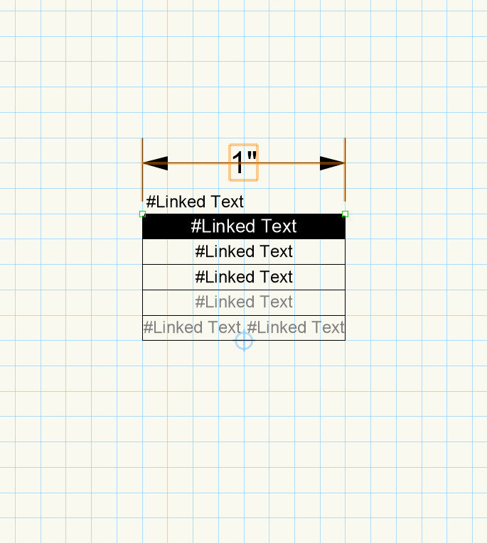
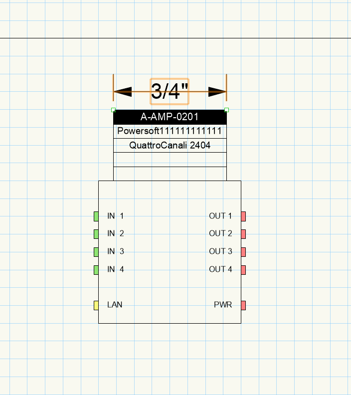
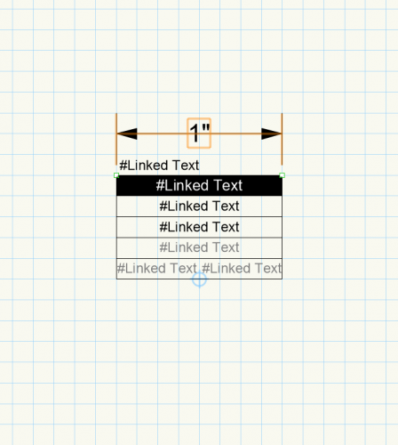
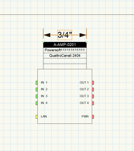
It seems somewhere the scaling is getting mess up in CC2021. I'm not sure where. Can someone shed some light on how this works? When I open the custom dev_label and go to edit the 2d side of things. All my scaling is correct. The box should be 1" wide. When I add a device to by design, the dev_label is 3/4" wide. All my scaling for my design layers are 1:1. These labels are carryovers from ones I built in CC2020. Has something changed about how custom dev_labels are handled? Thanks.
-
Thanks for the clarification. I do use the All layer cable report. I was just trying to easily parse out info that specifically pertained to connections outputting from the selected layer. After reading and understanding how CC build circuits, maybe I can build a report base on the devices who's layer is the one I looking for and go from there... Thanks!
-
Hello All, I'm trying to create a cable pull sheet to put in my drawings. My big dream is more of an Excel pivot table looking worksheet built from a database. Has anyone done this before? Thanks Chad
-
Hello All, I've been delving into really getting reports to work for me on our line drawing sets. I have a question as it pertains to the Current Layer Cable Report This works great for cables that stay on the same layer. But how would I go about making a report that would track the cables leaving one layer to go to another, like arrow connection cables tend to do?
-
Hello all! The new ConnectCAD is awesome!. I'm loving the changes. It gets better and better each release. In CC2021 I'm having an issue with my workflow. In older versions, I used to be able to build my entire schematic in one design layer, then when I was done, I would break out the devices into the various design layers I needed for printing. All at the end, all at once. All my Arrow connections that went to other pages would automatically be labeled correctly with the correct page # It was wonderful. It seems in 2020/2021 that isn't possible. I have to build all the devices, then make the layers I need, then do the wiring connections. Is there any way we can get that back? Sometimes after all is said and done, because of a Change Order, Etc, I have to move a device to another layer. When I move the device to a different layer, the arrow connections give an error (kudos on the warning symbol) and it causes me to have to delete all the arrow connections and rebuild, as they don't seem to like to reconnect on their own because of the layer mis-match. In the older versions this seemed to work smoother. Am I missing something? Thanks!
-
Thank you! Your settings is what we've landed on as well. I appreciate you talking the time to let us know!
-
Hello, I feel like I've tried every iteration of revit import I can, they all seem to have drawbacks. Can someone shed some light on your best practices? Or point me towards the information? The best results I've gotten it to import as vectorworks objects. My problem comes when there are angled walls (ex. exterior walls that join a slanted roof). Thanks!
-
Yes! How can I do that? I used to just change the design layer for the device to make that happen and it would include all the arrow connections. When I try to do that now, everything selects on the devices except for the arrow connections. I can select the arrow connection by itself, but when I change the layer it changes BOTH sides of the arrow connection.
-
Conrad, This file was born of a template that has evolved over different versions of VW. It encompasses custom layers, classes, etc, that allow us to build an entire construction drawing set (floor/ceiling plans, rigging layouts, High voltage layouts, connectCAD schematics) out of one VW file. When I upgraded to VW2020 my template was still available, so that's what I used to create this file. It's my first CC2020 schematic. I'd be happy to help you if I can.
-
Thanks you to you both for the help. The template is a new VW2020 template that was built upon my original one. But the devices are mix of new object from connectCAD 2019 and new ones from 2020. I am using imperial units. I guessing that's now a problem? I did notice the issue with the Rack Units when I would try and build devices... I guess I need to go back and rebuild all of my devices in 2020..