

Katarina Ollikainen
-
Posts
317 -
Joined
-
Last visited
Content Type
Profiles
Forums
Events
Articles
Marionette
Store
Everything posted by Katarina Ollikainen
-

Default Plant Record disappearing
Katarina Ollikainen replied to Carol Reznor's topic in Site Design
Hi @Carol Reznor, can you please elaborate - which record disappears? Is it the PlantMaster record? -
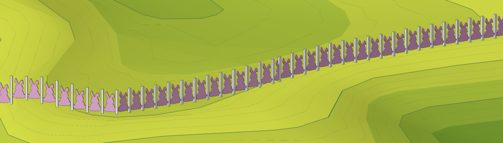
@Dan Johnson, In the image below, I've just extruded a shape, converted it to a symbol, and then used it as a fence panel (I have to admit, I might have been inspired by the season - I don't expect anyone to build a fence like that). The point is that your fence panels can look however you like. If you want to work with rails, there are a few more parameters to consider, but you have enormous freedom there as well.
-
Hi @zhoukaiyi, have you updated the site model? And if yes, can you please post the file so I can take a look? It partly seems like there is a z-fighting going on (both the site model and the hardscape having exactly the same elevation).
-
Lock Site Model!
Katarina Ollikainen replied to ericjhberg's question in Wishlist - Feature and Content Requests
@ericjhberg, this is definitely on our list of site model improvements. I can’t tell you how many times I’ve nudged the site model when trying to move objects on top of it. -
@hollister design Studio, instead of using a worksheet, select the data tag you’re using and set it in ‘tag all eligible objects’ mode. Hover over the planting plan and any plant without a data tag will be highlighted red. You can do this after you done the tagging, just as a security check that you haven’t missed any object. The only drawback is that you have to go into each planting plan - you can’t do the whole file in one go.
-
How to deal with large areas of meadow?
Katarina Ollikainen replied to Amanda McDermott's topic in Site Design
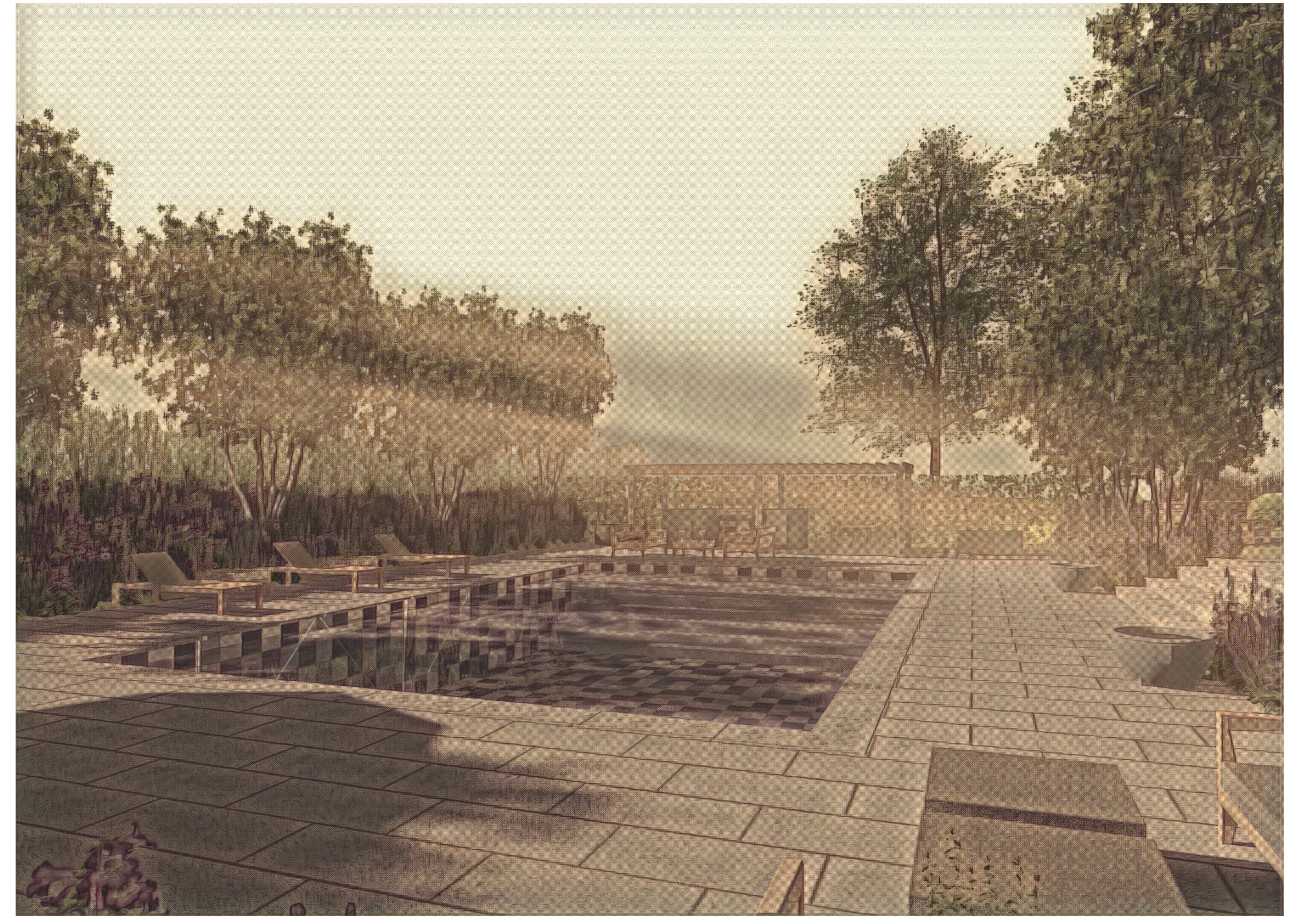
@Tom W., @Piotr Karczewski - I'm happy for either the marketing team or me to do something on this - the Coffee Break is probably a good place for it, as it gives you a chance to ask more questions. FYI, @JuanP, @Jake Chambers- perhaps a future subject? Below is an image of a landscape area containing plants, but I've also added a top component representing the plants - the result is similar to a hedgerow. Here, it has a texture with opacity, but you can keep it as a solid colour - if you're exporting to ifc, it can't handle textures anyway, so they'll be lost in translation. Again, solid colour is less weight than texture... I haven't actually removed the 3D from the plants here, but by not turning them on in 2D/3D I can keep the file much lighter. When working on larger projects, this is a very effective workflow. Start with concept LAs at different heights, this will give you a good feel of the space. As I said, this will be easier in the next version. The landscape area is getting a few updates. Don't feel like this is the only workflow - Vectorworks is great because you can adjust it to the way you want to work, as long as you learn a few rules (e.g., just because you don't feel for applying a grade limit to your site model, it doesn't mean you can skip it - the result will be affected). Sometimes, a small tweak can make a big difference - perhaps the planting block approach is not for you - then just be aware of what the 2D/3D does to the file size/graphics card performance, and optimize what you find most important. There are some incredibly exciting things coming soon, so don't despair if you feel like you have to pull back on visualisation compared to data.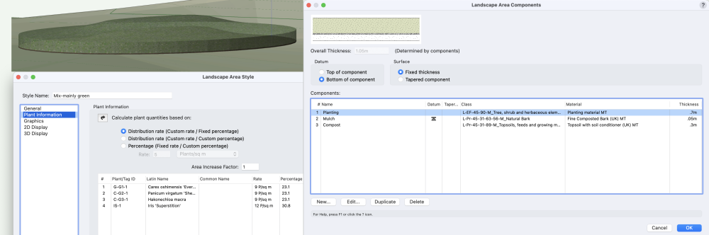
-
@Christine Mulinder, the same for you if you still have the issue. Please either post a file here or send it directly to me. If we can reproduce the problem, we can then start resolving it.
-
@inhabitats, I can't see the problem at my end - can you please post a file so I can do some research?
-
How to deal with large areas of meadow?
Katarina Ollikainen replied to Amanda McDermott's topic in Site Design
Hi @TeeMuki, it sounds like an exciting project. I'm worthless at advising on Windows machines, so I'll leave that outside this response. The below comments are specifically for BIM projects, as I assume you're more interested in the data and technical side than using the file for illustrations. One thing doesn't eliminate the other, but the focus is different. Strict discipline is important in a large project to avoid file ballooning. Avoid any unnecessary embellishment of your resources. Use simple circles for 2D plants without unnecessary vertices, use generated 3D views for the trees (but avoid the 'sweep' modes - the 'crinkled paper' ones are lighter). I don't even have 3D added to most of my plants as standard - a planting plan is a technical document, not an illustration. Removing image props from your plants will greatly reduce the file size. There are more effective ways to create illustrations for a project than using the planting plan directly. If you're working on a BIM project requiring you to deliver a 3D model, the polygon-with-record-route is not feasible, so Landscape areas/Hardscape are the way to go. Since an earlier update this year, the LA has been optimised - if you don't show the plants in 2D or 3D, the LA is extremely lightweight. As soon as you add 2D or 3D plants, it gets heavier, and of course, both 2D and 3D is the heaviest. You can have the plants included in the LA without showing them - the data is not heavy, the graphics are. So from that it follows: if you want to represent large areas of planting in 3D and show the plant volume, I suggest using a component block for the plant - instead of using the individual plant's 3D, simply create a top component (above the datum) called 'Green matter' or similar to your LA (you can make it as thick as the average height of the planting) - for a BIM model (which is primarily not for illustration but for construction and clash detection), this will work great. This will also help with design decisions, giving you a better idea of volumes and voids in the landscape. There will be some improvements to the LA next year, making this even easier. Regarding the question about 3D polygon vs texture bed; You can show LA in a few different ways: As components, as texture beds (without components), and as a 3D polygon (without components). The 3D polygon really has no function. If you're working over a site model, you must either have a texture bed or components visible; otherwise, the LA won't be following the site model terrain. As soon as you decide to show components, these will take over. It then doesn't matter if you have a texture bed or 3D poly (and components are required if you're working in BIM and want to export to ifc). The setup in the LA dialog is confusing, and this will be simplified next year. If you use hatches for the 2D view, your graphics card might suffer, especially if the project is large - this is the same for both hardscape and Landscape areas. I suggest using plain colour for the 2D and running it with a data viz, adding hatches if you need this for your plans. This makes a huge difference. Apart from this - ensure your site model is optimised as well. Otherwise, this can contribute to a sluggish file. As a comparison - I have a 'stress test' project with a site model at 1471084 m2, 4858 trees, and landscape areas (with and without plants added, so both meadow and dense specified planting) covering most of it, and it runs beautifully. Now, this file doesn't contain all the other niggly things in a file as it focuses on these specific components, but it shows that you can use large areas of planting/hardscape without destroying the performance. It is a trade-off, I know, but if you're working on a BIM project, data is king, and you must focus on that. -
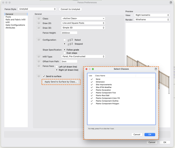
@hollister design Studio, I'll file a jira on this straight away so we can look at the effects. Thank you for highlighting this. The idea is for the style to save information about classes you don't want the send to surface to work on (that you have manually unchecked) to avoid the need to do this process for every project (if you don't want a fence to listen to a specific class in project A, then you probably don't want it to listen to it in project B either). This is the effect I get when testing it. However, I'll see if we can avoid creating the classes in the new document until they're created/used outside the fence style. I'll let you know when I have some more info.
-
@Michael Siggers, have you watched the fence tool video? If not, please follow the link below. If you still have questions after that, please message me, and we can meet on Zoom and go through them. Our aim is always to make our features as intuitive as possible - however, this has to be put into the context of who our audience is and what you want to produce. If you're a BIM manager, you'll need very different functions than if you want to do a quick-and-dirty concept model. You might also have different prior knowledge and experience of similar features. I've noted the help text issue and will look into this. I think the message should have been updated after the tool's terminology changes. Thank you for noticing. The fence in the image above looks like a prime candidate for a pre-constructed panel, as @Tom W. suggests. I am, of course, not aware of your priorities - how you decide to go will depend on this. https://university.vectorworks.net/mod/overview/view.php?id=5719
-
@Michael Siggers, Hi, the only time the class has any bearing on whether the site modifier will work is if you're using objects other than the standard site modifiers to act as site modifiers (e.g., 3D polys or NURBS curves). In these cases, they must be placed in the Site-DTM-Modifier class. Background: If you ungroup a site modifier (I don't mean that you should do this, it's only an explanation of where it is important), you'll get a 3D poly in the class Site-DTM-Modifier - this is what's actually 'the active ingredient' in the modifier and where the class is essential. What class you place the whole site modifier in doesn't matter. Many objects can contain site modifiers - hardscape, landscape areas, roads, massing models, certain blue symbols, etc.; the same is valid here - you don't need to place the objects in a specific class for them to work. The important thing is that they're placed on a layer that the site model is set up to consider.
-
Archicad dwg files to a referenced VW site model
Katarina Ollikainen replied to Minna's topic in Site Design
@Tamsin Slatter, do you have any input on this? I know you did some research on Archicad. -
Site model snapshot - can this be used for terrain modelling
Katarina Ollikainen replied to MMGD's topic in Site Design
Hi @MMGD, if you ungroup the snapshot while in 3D view, you'll get a 2D image of the site, a mesh, and a set of contours with z elevation. Ungroup the contours, place them at the correct coordinates and use them to create a site model.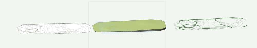
- 1 reply
-
- 4
-

-
Hi @Phillip Tripp, thank you for taking the time and effort to collate this list - I will respond in this thread but will first contact you directly for some additional info on some of the items.
-
@kwik, You will be happy to know that we're working on all of these functions; however, some will be part of the new road tool and will not be implemented separately until then. We fully agree that these improvements will make it much easier to work with the modifiers - we just want to ensure we're creating a solution that will cover all the intricacies of the roadway as well, otherwise we'll have to reinvent the wheel for that. It is really good to get this feedback, though - it helps us focus on the most important features. Please continue to post ideas and wishes, as well as examples of functions that could be improved. The more detailed, the better.
-
@PieConk, this is not determined by layer, but with classes. By default, all classes are active to receive a fence. If you have a building with eaves and want a fence to go below, all the way to the wall, simply uncheck the class of the building/roof in the dialog. The only two things that the gravity mode never works on are site modifiers and plants, no matter what class they're in.
-
@Poot, @aage.langedrag, - both Bobi and I have been looking at this today and we've found a bug relating to the new site model system. I'm filing a Jira on it and will update this post when we have a fix.
-
Sorry, I was responding before my morning cup of coffee. Correct, there is no 'Locate in resource manager'' in the context menu for the plant. I've made an enhancement request and added it to plant improvements.
-
Landscape Area to Hardscape Object, or vice-versa
Katarina Ollikainen replied to Neil Barman's topic in Site Design
@aage.langedrag, Great, that's what I thought. It wouldn't make much sense to change an ongoing project if the object is already doing its job, just because it's titled 'landscape area' instead of 'hardscape'. I'll have a look at the sample file. -
Landscape Area to Hardscape Object, or vice-versa
Katarina Ollikainen replied to Neil Barman's topic in Site Design
Hi @aage.langedrag Do you mainly want to convert styles or individual objects? Can you please send over some examples of what you would like converted? This should include all p-sets, attached records, etc., so we can understand the scope. -
I, in turn, must thank @KAngelov and @Vlado for their help. It takes a village...
- 6 replies
-
- 3
-
-

-
- plant record
- worksheet functions
- (and 1 more)
-
@line-weight, The fence tool has been available for beta testers since last summer, which would be user testing. The feature has been out for general use since the 2024 release in September - this is the first comment I've received about this design aspect, and we're looking at it. I'm grateful for anyone with constructive criticism and comments - that's how we improve. In this case, I agree that the feature could be more user-friendly - it’s also an area where I’ve other ideas I would like to see implemented (based on another tool I’m working on right now). Sometimes, things are discovered after prolonged use; sometimes, a eureka moment hits you right before release. The latter can be the most frustrating for our team - it's far too late to change it, but you already have something even better in mind. For the fence, my biggest regret was to include scaling of 3D symbols. There will always be room for improvement, but there will also always be someone who does not like what we create. This doesn't mean we shouldn’t always try to produce the very best. We have a team of brilliant engineers making our ideas come to life - they put so much effort and energy into our product, and (IMHO) they create some fabulous, innovative features. The 'people at the top' take UI and UX seriously, and we are constantly working on keeping the tool approach consistent across the Vectorworks application. The TechPub team (who create the Help file) is invaluable in this - they look at every feature from a unique viewpoint as they service all industries and look at each and every dialog while writing instructions for how to use them. The process of developing a new feature is really an effort by all levels and teams. This is what makes it so much fun to do. Also, we now have a product planner specialising in UI/UX, @Stephan Moenninghoff. Last year, he did an enormous job with the workspace redesign, but even there, we have the same situation - some love it, and some are less enthusiastic. Some find it making their life much more straightforward, while others think we have made some wrong decisions. And I'm sure Stephan already has a list of things he would like to tweak. All this doesn't mean everything is perfect, and I can only reiterate our gratitude to all of you who gives us constructive feedback.
-
@Tom W., absolutely no problem 🙂. Your idea for settings is a good one - I'll see how and when we can implement it.
-
Always sorry to create a Yuk-response. I have marked this as 'look at' for the 2.0 Fence. The difference to the door is that gates are part of the fence, compared to separate objects in the wall. When you flip a door, you're doing it immediately. When you flip a gate, you're in a dialog editing something that belongs to the whole fence, and no changes are being made until you exit the dialog.


