
bgoff
-
Posts
291 -
Joined
-
Last visited
Content Type
Profiles
Forums
Events
Articles
Marionette
Store
Everything posted by bgoff
-
if you are referring to using a terrain model, just set multiple pad modifiers at various elevations to modify existing terrain. Or by double clicking the DTM you could use the proposed site model surface button (or existing) and use the sculptor to create the mound. Or if starting from scratch you could create concentric lines representing the elevations required convert to 3D polys and set a z value for each then select all and create a DTM. Hope this helps.
-
@lisagravy I was just on with Tamsin, I now better understand your question on how you are using it there. I will research this and I am positive Tamsin will have an answer for you locally. As for moving the stake, it can be moved but only using LAT/ LONG not to be moved by Meters X/Y. To move use the "Set Location" Button at the bottom of the OIP for LAT/ LONG. To move by meters in an x/y fashion it cannot do that (or at least I haven't figured it out yet). Hope this helps.
- 28 replies
-
- 1
-

-
- gis
- georeferencing
- (and 3 more)
-
First set your file to use OSGB 36 Datum, Then set the origin (search for) 49ºN, 2ºW (this is British Grid Origin) and it will set the point. You can also go to the File Georeferencing dialog and set the coordinate points of 49, -2 there also.
-
This can sometimes happen when your site location is very far away from your origin point, as it looks like it is. Try locating this (in a copy file) closer to the internal origin and see if it improves.
-
Ahhh, yes at this time if you are working in MM you would have to then change to Meters for the correct units. I will add this as an enhancement!
-
Paul, for clarification. You are looking to move or delete the contour labels or are you looking to change from feet to meters or meters to millimeters, or the like?
-

Share plant database in work group folder but cannot use at the same time
bgoff replied to Sally yang's topic in Site Design
So if you are both pointing to the correct location, and you each "get plant Data" in the plant preferences> plant style dialog box. Either can access the info? Ensure you are using Edit Plant Style and then Get Plant data. -
Share plant database in work group folder but cannot use at the same time
bgoff replied to Sally yang's topic in Site Design
Question. Are you opening the Plant database on its own or through Vectorworks? Open Plant data. Also Do you have this issue (Plant Database not running with this step) if you "get plant data" within Plants in Vectorworks. -
Share plant database in work group folder but cannot use at the same time
bgoff replied to Sally yang's topic in Site Design
what is in the Vectorworks Plant database file? -
Share plant database in work group folder but cannot use at the same time
bgoff replied to Sally yang's topic in Site Design
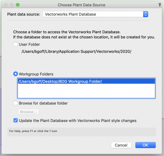
here is an image of my setup. Then go to choose plant data source and look to the leading folder.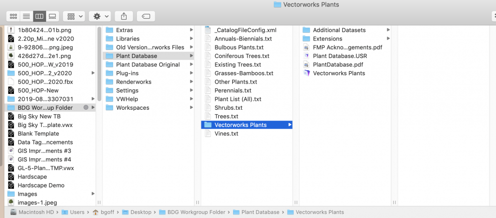
-
Share plant database in work group folder but cannot use at the same time
bgoff replied to Sally yang's topic in Site Design
sounds like the setup might be wrong! First does your workgroup folder work properly for other files other than plant database? -
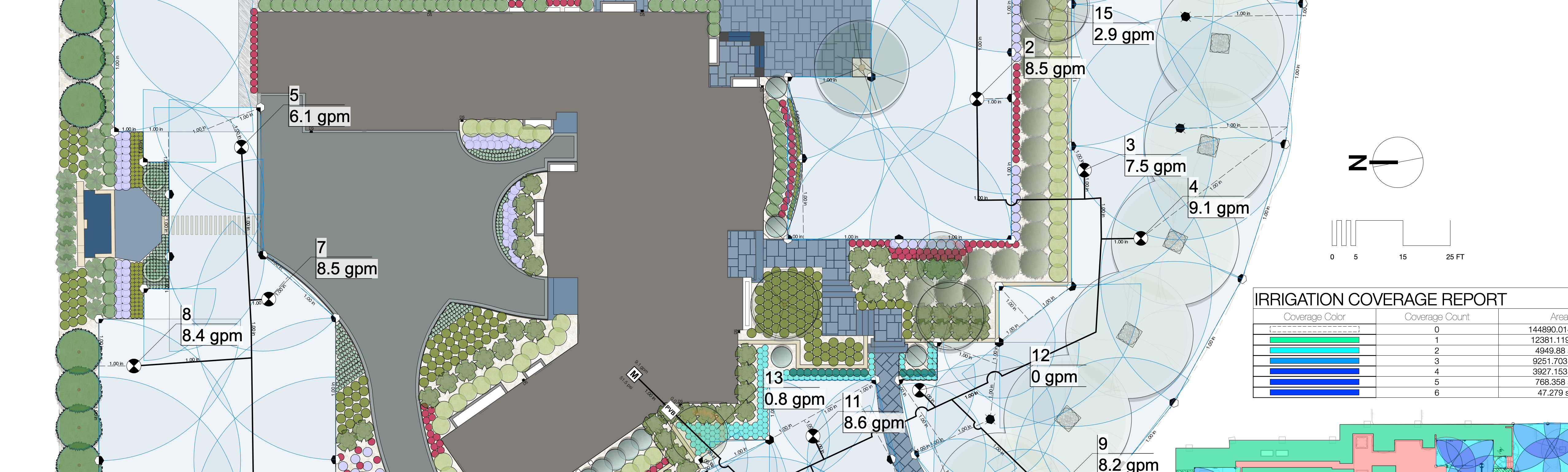
If you are snaking the tube then I find it easier to do tube first. It all depends on the plantings. If they are close to each other I prefer to use a branched network instead of one long continuous line. the long line produces to great a pressure for the system to run correctly. A branching network that is tied back to itself will have a more even flow and less pressure.
-
As for Live Data Viz. Wow! it is fantastic! You should really try it.
-
No you can snap as many emitters at that plant as necessary. Also this will allow you to use specific emitters. .5,1,2,3 + GPH based in the water need and where to place them.
-
I am having issues trying to reproduce your issue. when I try it. it works fine for me. could you post a video of the steps you are taking?
-
I'm curious! Why not use the Drip Pipe (no emitters) and place the emitters (in outlets) on the pipe. You could also use Live Data Viz to show the plants per size parameter. This would make all emitters connected to network allowing for proper calculations. I will try what you are proposing, might be great but also might be a lot of extra steps which can add to error. But hey! I haven't tried it so you might be on to something.
-
are you connected to the internet? PC or Mac? Also try to search Globaly not from user location.
-
@Matt HallI get what you are saying (I think) these could be files in a workgroup folder. Files as Cabinets, Plumbing, millwork, lighting, Etc... then just grab the symbol in that file and use it in your working document or reference it in if you like that workflow. The symbols of those will keep their Classes so will load your file with the appropriate class if it is not there. I hope I'm getting your issue correct.
-
@markdd good point on the symbol referencing. that would do it but you still need to update the references. Its easy but is a step. As for the workgroup folders. Follow the help instructions and contact tech support for any issues.
-
No! the symbol instance in each drawing is different. this is done on purpose. if you are trying to update one symbol instance and have it modify all symbols in all files, I do not know if that can be done. And out of curiosity I am wondering why? Just really curious on your workflow need. I'm always up to learning new workflows and requirements.
-
@antonf26like we discussed in your other post. Create an area or polygon around the bed and name it at the bottom of the OIP (Object Info Pallet) then set the criteria in the worksheet to look for that area. As for labeling you could create a custom Data Tag for this or just label it with text or the callout tool.
-
The key is to set a local coordinate system. you can double check the process by using the great circle tool. Sounds like you have it set to pseudo mercator which depending on your location will scale everything (image ) wrong. The closer you are to a coordinate system and point on the earth the better you will be.
-
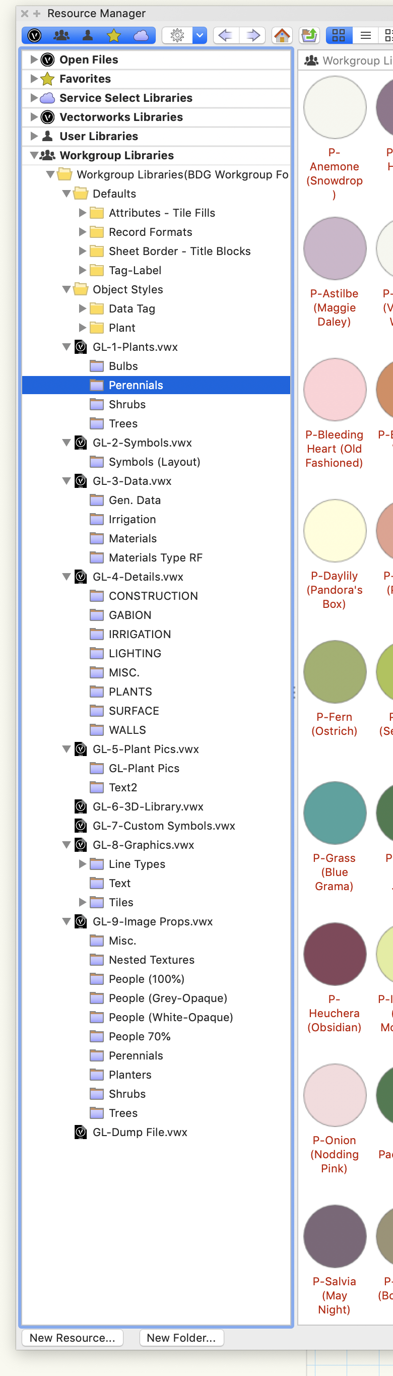
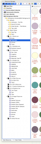
I like the process of an empty (no major resources) Template file. This will have all your layers, classes, sheets and title blocks in it. This keeps the startup file small and clean. Then use Workgroup Libraries to define your symbols, graphics and the like. I have numerous files in my WG folder that allow me to quickly find what I want. See attached Image.
-
These could be set up and appended to one worksheet also. It really depends what you are trying to show. For instance, If you have an entire design but it is in say 3 phases and you only really need to show phase 1 for plants and pricing. You could have one worksheet showing just that phase and ignore the rest for the future. or if you need all three phases to show indpenantly this could be done in one worksheet or three. I like having different worksheets because if you use a regular naming structure for the phases or areas once the worksheets are made you can use them in the future. This way if you have 20 now and the next job only has 5 areas then use worksheets 1-5 and so on. Hope this helps clarify.
-
@antonf26try drawing a box or polygon around the area and name that shape in the OIP. Make sure the plants are not tied to others outside that area or it will count the also. then set the parameter in the worksheet to look for that shape. Set the worksheet to Location> is within> NAME OF SHAPE!