


DuncanR
-
Posts
29 -
Joined
-
Last visited
Content Type
Profiles
Forums
Events
Articles
Marionette
Store
Posts posted by DuncanR
-
-
Realise this but i've created the data vis to highlight other information and will be using it on other projects where we have moved on from the inner/outer wall details so easier just to keep it on.
-
On 5/12/2022 at 5:22 PM, Tom W. said:
Is it possible to use class overrides on the Wall component classes instead? Then the window wrapping will be grey too
If i do this on top of the Data Visualisation I can get them to show all a solid colour. Not ideal but it will do for now. Thanks Tom.
-
20 hours ago, Tom W. said:
Is it possible to use class overrides on the Wall component classes instead? Then the window wrapping will be grey too
I'll give this a shot and see if it will work
-
Hi Matt - This is an existing project that is now nearing completion and we are preparing As Built information. Don't really want to go through all the window styles changing from the Ext/Int wall Detail to Wall closures, especially since there are ongoing issues with the wall closure, e.g. wall closure hidden when a sill is used.
-
Any solutions for this come to mind? It is rearing its head again for another project i'm working on but can't for the life of me find a solution
-
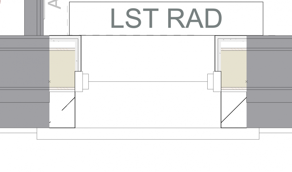
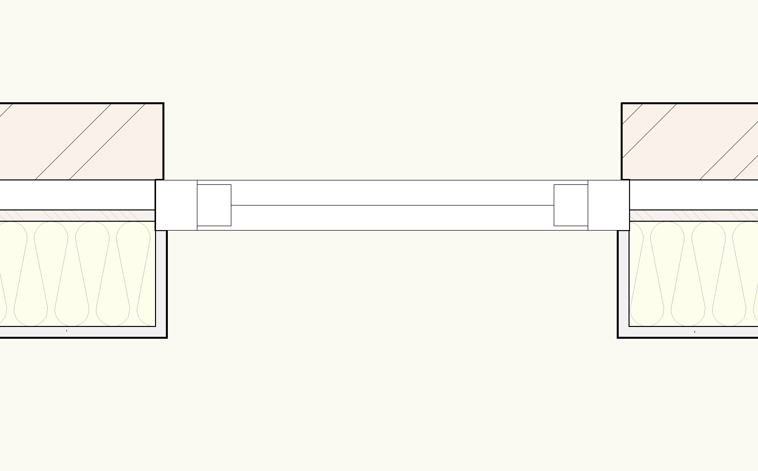
With SP3 released I was hopeful that the wall closure issues might all finally be resolved so we can put them into use.
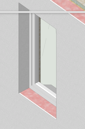

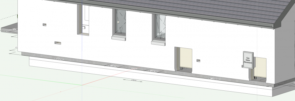
I have to say I have finally managed to get the component wraps at the closure to work for a window in both Top/Plan and 3D.
...until i introduced a sill.
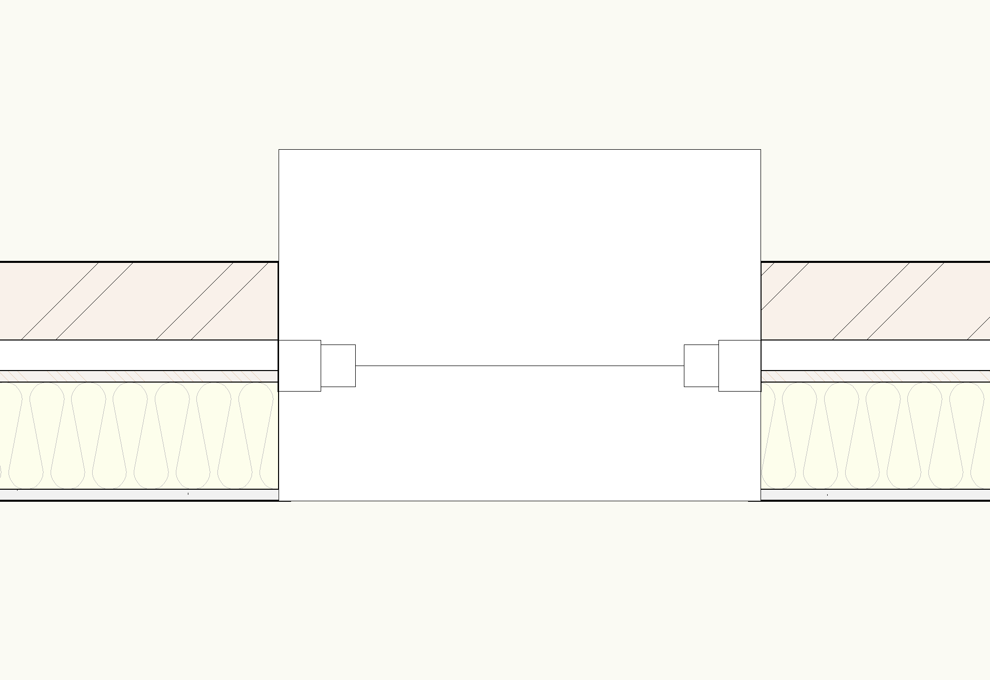
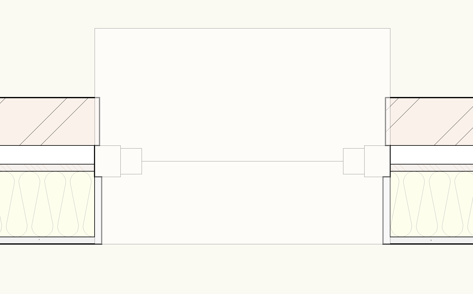
As you can see, with the opacity turned down the closure wraps are located behind the sill. I have tried adjusting the cut plane but it appears to have no effect. Neither does amending the draw order.
Am i missing something from the multitude of options that can affect the wall closures or the window visibilities or is this the next bug to be solved with this function?
I have used stock vectorworks wall style and window style from the library for testing this as a baseline, file attached.
Out of interest it would also be good to know why the sill colour fill projects all the way to the internal face of the wall no matter the sill settings (We'll leave the need to include an internal sill option for another day)
Hopefully @JuanP or @Matt Panzer know what's up.
-
20 hours ago, David Poiron said:
This is how we do things currently but it would be helpful if we could simply refer to the wall width - this allows the door manufacturer to have more direct information, which we think would lead to fewer issues in the field.
Agreed, however i'm not aware of any way to do this currently. Maybe one of the pros will know @Matt Panzer?
-
We do this by reporting jamb size for internal doors as we design for timber construction so we have it set to 'use wall depth' anyway
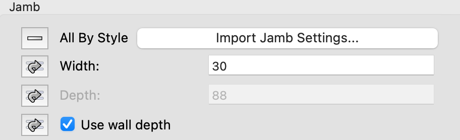
You could do the same for external doors but we don't because it looks unrealistic on our GAs. Unsure how you would report the wall thickness if your jamb size differs i'm afraid.
-
You could also do your fascias as an extrude along a path. That way you can have a standard library of profiles for use.
We use this approach for almost all fascia/soffit arrangements as the built in tool just doesn't do what we want it to.
-
 1
1
-
-
6 minutes ago, Matt Panzer said:
I think the best way to handle this is to Cut and Paste in Place the Section Line which will convert it into an independent section line (no longer defines the viewport). You can still keep it linked to the viewport (for auto document coordination) via the Object Info palette but you can change the object freely (including its style, shape, etc) without altering the viewport or the section lines defining the viewport. Of course, this also means that it will no longer move along with the defining section line objects if they're changed.
Thanks Matt - Not an ideal solution - almost as well doing just a stand-alone annotation.
With the every increasing number of elements that can be set/controlled via styles (data tags etc.) I'd think adding the ability to scale styled markers within the viewport advanced properties is something Vectorworks should look at including in a future release. Even tying them to one of the existing scaling options (markers or symbols) would be a step in the right direction.
-
1
-
-
Hoping someone can help with this and we're not missing something obvious.
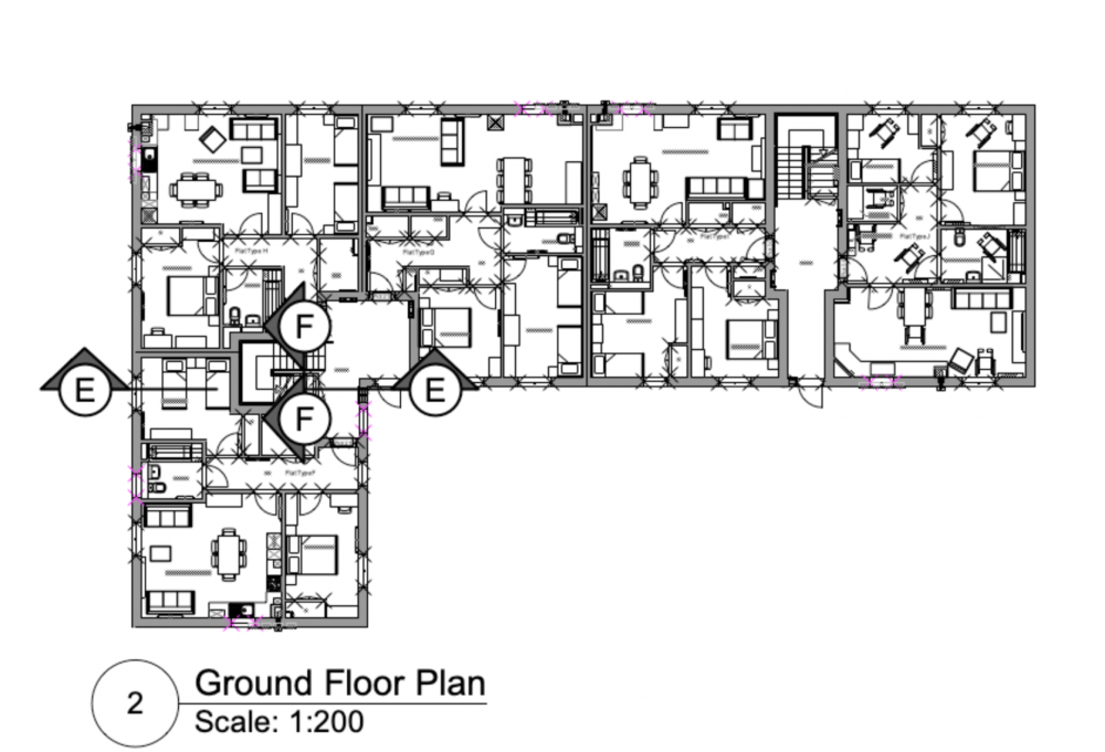
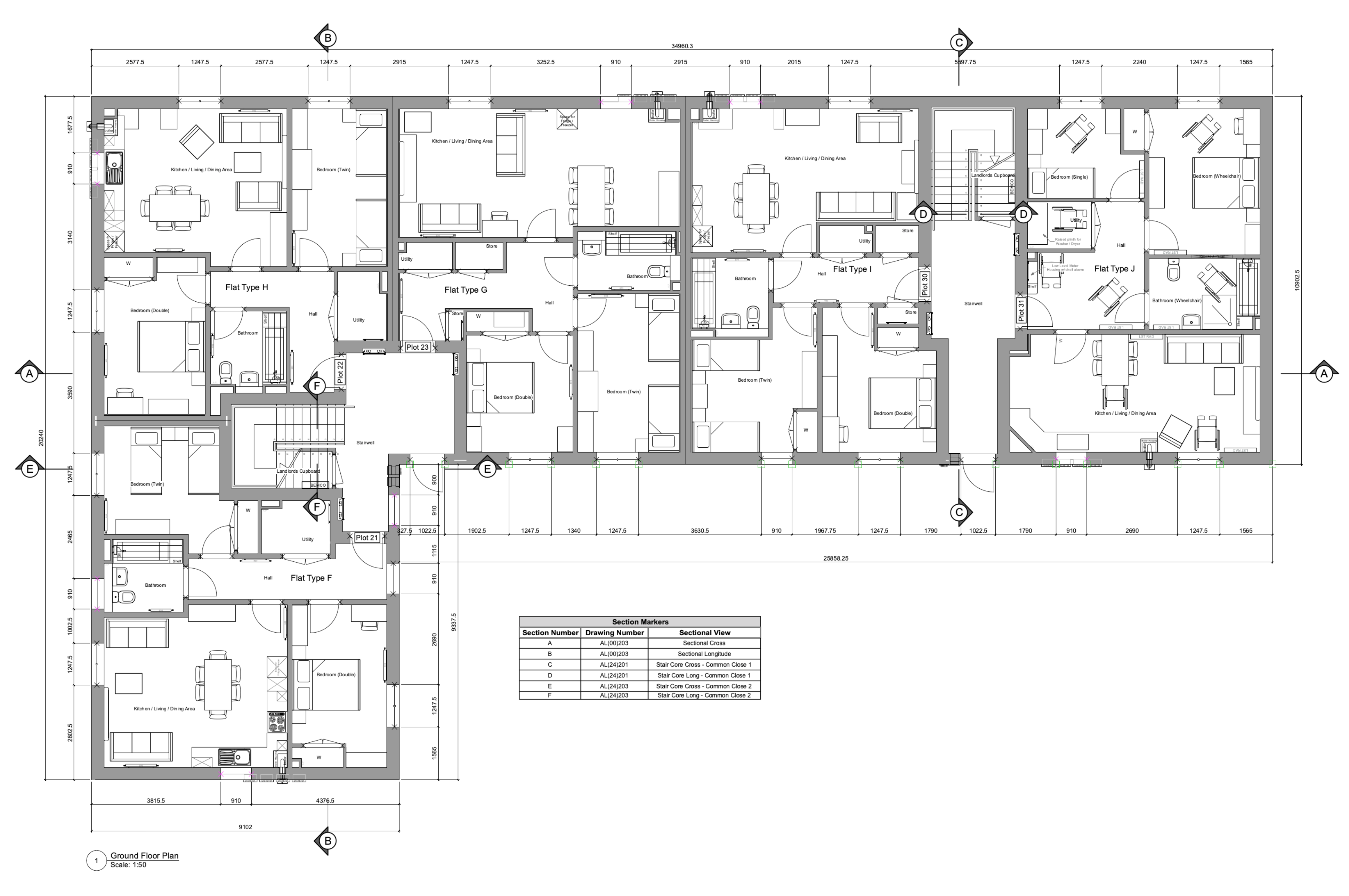
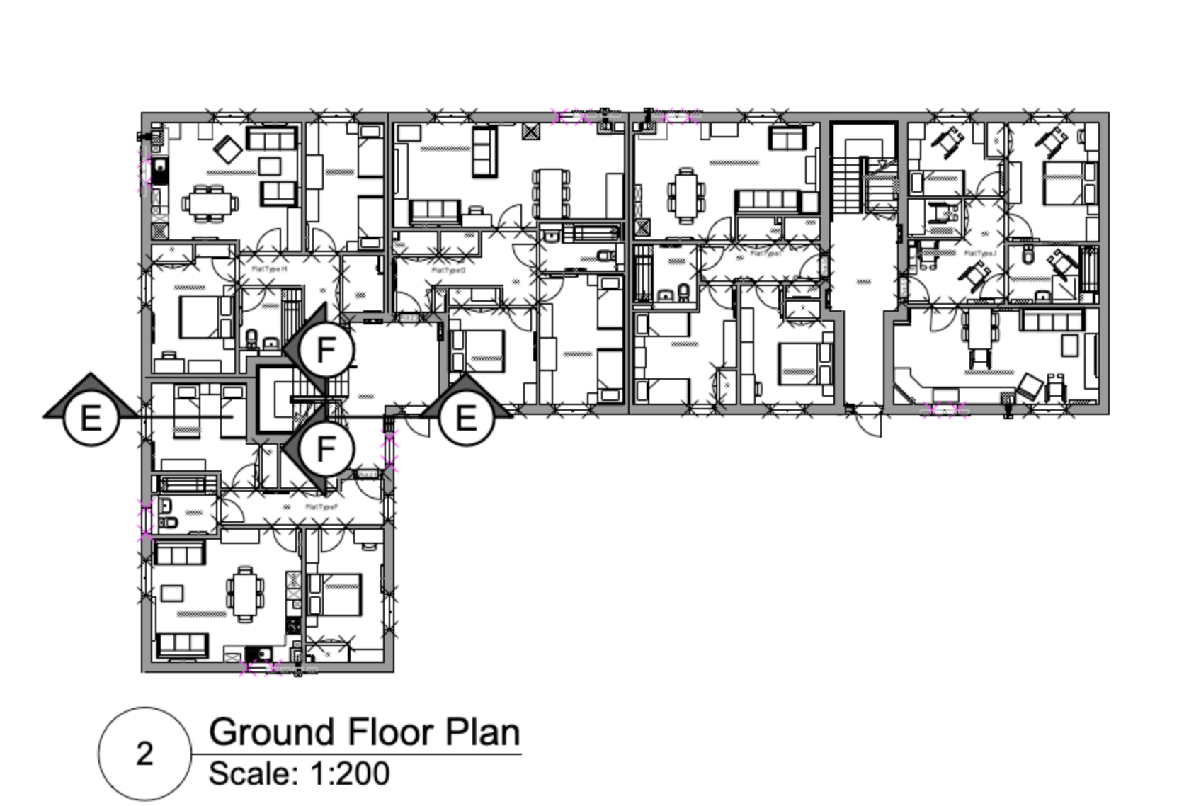
When using coordinated section markers on a plan viewport (1:50) we also show these on the section sheet layer adjacent to the associated section viewport in a contextual plan viewport at a smaller scale (e.g. 1:200) - to allow those reading the drawing to easily identify where a section is taken if reading the section drawing in isolation.
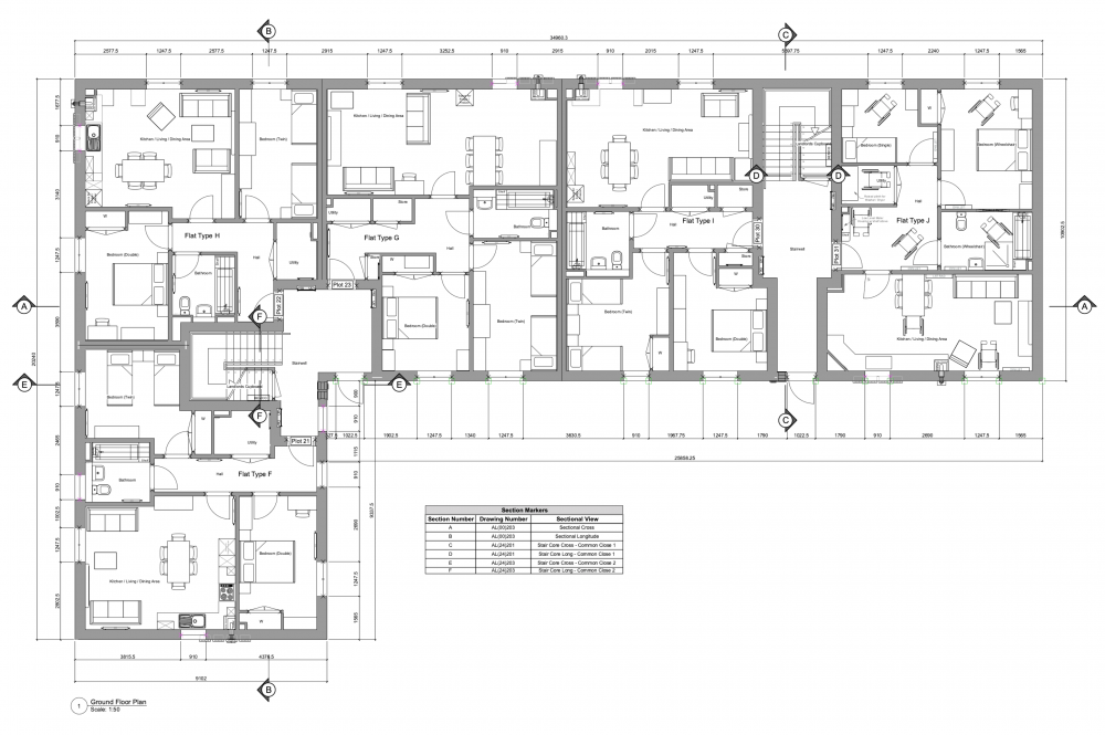
Our issue is that the scale of the section markers on the 1:200 scale context viewport appears to be a universal setting across all instances of the marker that are associated with that particular section viewport, meaning they show as either impractically large on the context plan (as shown below) or too small on the main plan if scaled to suit the context plan.
Trying to scale markers/symbols etc. in the Advanced Properties for the viewport doesn't appear to affect them and if we change the scale factor for the marker in the annotation layer of one viewport it affects the markers in all other viewports.
Is there a way to individually scale these markers for legibility?We are currently working off VW 2022 SP1.1 - While we are aware that SP2.1 is the latest version, there is a known issue with wall hole components of symbols attached to walls that is yet to be fixed.
-
1
-
-
Thanks for confirming Matt.
Unfortunately, removing the symbols from the wall isn't an option as this affects every live project that we are working on..that's a LOT of sockets, furniture etc.
Following a phone call to SS tech support we have reverted to SP 1.1 until the issue is fixed. Luckily CMD+M with a value of 0 for a single symbol in each wall or opening the roof edit dialog and closing with no action at SP1.1 seems to fix the issue on the 'corrupted' file.
-
Recently updated to SP2 and upon opening a project file to make some changes I've noticed that if i amend a wall, a symbol in a wall or an element connected to a wall (e.g. a roof) all 'symbols in walls' start showing a wall hole around the extents of the 3D symbol objects.
Wall breaks are off and there are no wall hole components in any of the symbols. Even checked the new wall closure options to make sure they hadn't been activated as a default but they are also off in both symbol options and wall style settings.
Undoing the change to an element reverts all items back to normal.
Bug Report submitted but interested to see if anyone else has had this issue with SP2?
Attached both the file prior to any changes made with SP2 and after roof edit dialog has been opened and closed with no change so it has affected all walls connected to it.
-
They introduced styles for Drawing Labels in 2021 so the OIP for more recent versions will likely be more streamlined as more of the functionality is done by style rather than by instance.
As markdd stated the tutorial video is probably just outdated and the Help files or alternative tutorials like those provided by Jonathon Reeves should give you the information you need.
-
Hi Matt,
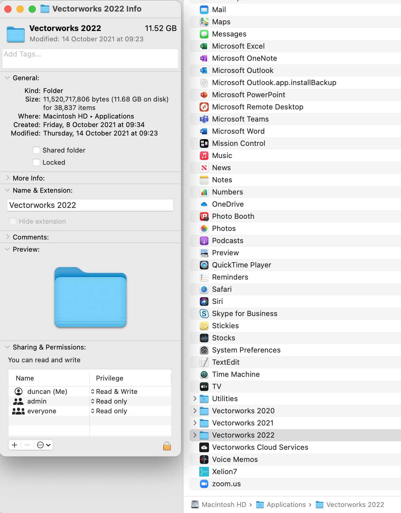
I've had this issue previously. You need to have read/write permissions for the vectorworks application folder (which contains all libraries etc.) on your system.
Easiest solution I found was to go to your application folder > right click on folder e.g. "Vectorworks 2022" > Get Info > amend "sharing & permissions" so that your user account or admin (assuming you have admin rights) can both read and write.
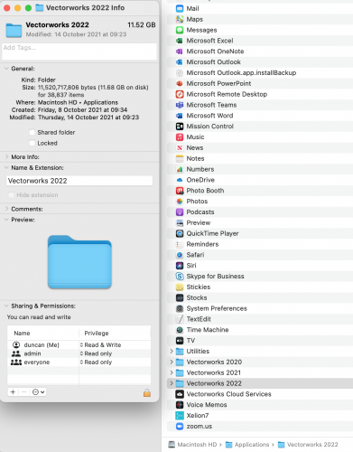
sidenote: you also need these permissions set if you want to be able to manage door hardware sets etc.
-
Just now, hollister design Studio said:
I sent the file in to tech but I will try this if it happens again.
Glad to hear I'm not the only one!
Absolutely. Vectorworks need to sort this from happening in the first place, or at least push out a solution quickly, rather than leaving it up to the users to find a workaround or go through an onerous process to fix something we shouldn't need to be fixing that eats up a chunk of the limited hours we have in the day to do our jobs.
We also can't sit and twiddle our thumbs while they analyse our files.
My biggest concern with Vectorworks from my experience is that I simply can't trust that work i've done days or weeks before is still going to be the same the next time I look at it. It adds hours of checking and rechecking on to my time.
-
I had this problem occur for me when section line/marker styles were introduced with VW 2021. Sections would display as if no issue but the marker/line locations were all over the place and if you tried to manually reposition them it would mess up all the annotation positions.
Solution I found was to:
Go to your sheet and select your section viewport. While selected go to the OIP > Section Line Instances and untick all of your viewports that are active. (If you've not renamed your viewports from the default generated names take a note of which ones they were turned on for or rename your viewports at this point so you can easily turn them back on for the correct drawings)
Then just simply go back in to the section line instances in the OIP again and turn them back on for the viewports you want them to show in and they should now display in the correct position.
-
1
-
-
had the same issue. It seems that may be an old route for installation pre VW 2021.
Go to: Help > Install Partner Products > NBS Chorus
Once installed you will need to restart VW then once you reopen there should be a new palette for NBS Chorus open as a default
-
2
-
-
17 minutes ago, Nikolay Zhelyazkov said:
- Seems like such.
Here is a file with a script that you can use to get rid of the invalid TBBs. It will delete all TBBs in the None class, which seem all to be corrupted, not selectable and invisible...
If you see this issue again, let me know here. It will be very helpful if you find out how did you end up here.
Best Regards,
Nikolay Zhelyazkov
Thanks for that Nikolay that appears to have sorted it.
Will do.
-
1
-
-
4 minutes ago, Nikolay Zhelyazkov said:
Thanks, @DuncanR,
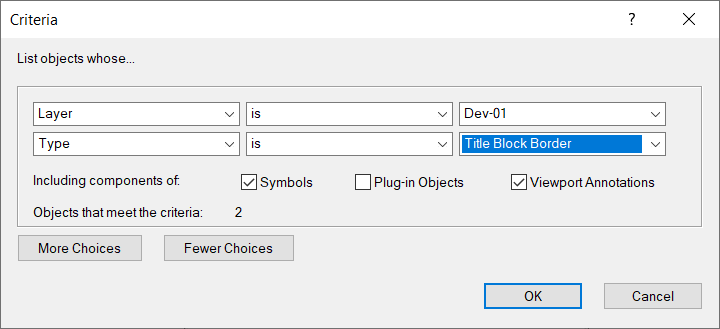
It seems like you do have 2 TBBs on each sheet:

However, the duplicates are not visible or selectable. I am not really sure what exactly caused these TBBs to simply disappear and not be selectable. Do you remember doing anything specific before getting these 2 > ?
Best Regards,
Nikolay Zhelyazkov
never thought to use a worksheet to check for number of title blocks. I have been through all annotation layers as well using select all and manual scrolling through the selected items in the object info and there are no other title blocks identified.
nothing has been done differently for this project than any other at our company.
I also cannot select the item via the worksheet to delete it. Is this simply a corruption of the file/ghost
-
1 minute ago, Nikolay Zhelyazkov said:
- Hello @DuncanR,
Could you send me a test file which I can analyze, so that I can see where the problem is coming from?
Best Regards,
Nikolay Zhelyazkov
Nikolay,
Please see attached
-
We currently have an issue in the title block manager where we are getting the '2 >' drop down under the revision data of all sheets but no '1>'. As if there are multiple title blocks, as stated above, but we have checked and there is definitely no second title block on any of the sheets.
This is causing VW to incorrectly identify the 'current revision number' in the file name when publishing (I assume because it is taking the 'current rev number' from the '1 >' rather than the '2 >' which it has reassigned everything to. While not a major issue it is added time/chance for a mistake if anyone publishing has to manually rename the file each time.
Is there anything else that could cause the multiple drop downs from being generated?
-
Afternoon All,
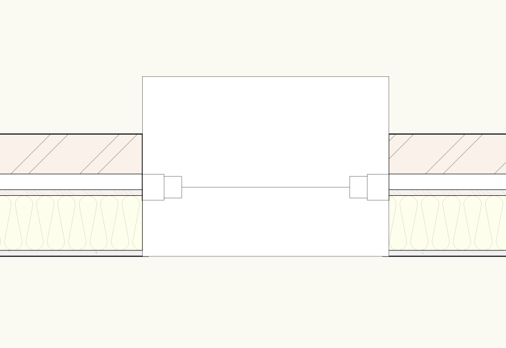
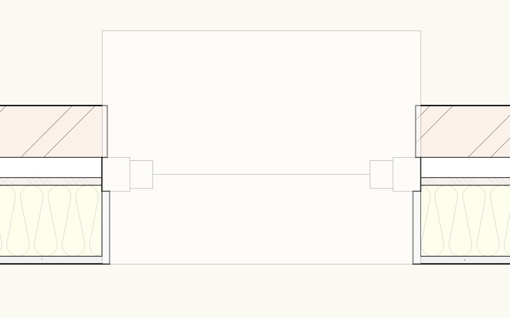
Does anyone know how to apply data visualization to the exterior/interior wall components governed by plug in window symbols?
See below example of a simple data visualization that turns all walls grey. As you can see the wrapped wall components that are part of the window symbol have not taken the grey fill.
Is there a specific criteria that controls these elements that can be added to the visualization criteria? I would have thought they would be an extension of the wall they are inserted into and would display the same as the wall to which they are attached but clearly not.
Ideally for a simple grey fill we would utilise the wall type attributes and low detail level but unfortunately this is an existing project (prior to our use of data visualization) where said wall style attributes have been used to assign different colours to different wall types.
Hoping to avoid having to go through the project amending all wall type attributes to show grey at low detail and applying a data visualization for the colour coding.
-
2
-
-
Due to upgrade to 2021 this weekend so fingers crossed 🤞
Also we upgraded my colleagues workstation to 32GB RAM in the hopes it would resolve the issues for them but it made no difference, so who knows what the issues was.
EDIT 19.10.20 - Updated to VW 2021 over the weekend - Happy to report interior elevations appear to be working a lot smoother and visualisation issues haven't been evident so far.


Saved Palette Positions Issue
in General Discussion
Posted
Anyone else having a problem with saving palette positions/sizes in 2024?
Despite using 'Save Palette Positions' each time, I have had to resize all palettes on the left and right side whenever I start up VW2024.
Also If I accidentally grab and drag the top bar into windowed mode vs full screen it makes the window tiny and again resizes all the palettes (at least only the first time it happens each session).
Very frustrating - Is there something I'm missing or is this a bug? I don't remember having the same issue with earlier versions.