


BobS_50
-
Posts
26 -
Joined
-
Last visited
Content Type
Profiles
Forums
Events
Articles
Marionette
Store
Posts posted by BobS_50
-
-
29 minutes ago, line-weight said:
Yes, I am seeing the bug in that one, viewed in VW2021. So it looks like it exists in a HSVP created by clip cube but not by menu command?
I have a vague memory about there being something different but not made obvious, about 'normal' sections according to whether they were created by the clip cube or not, in the past. I can't remember exactly what it was though.
...
Seeing your test viewports, noted up with the different settings - I have to do the exact same thing at times. When intuition and the VW documentation can't help you - this is what you have to resort to; time consuming detective work. I currently have an 11-page document with all my own notes on how to make VW work. Effectively, writing my own user manual.
In this instance the fail was from a clip cube...elsewhere its been from the menu command ... I found another issue when I tried to amend the view from orthographic to perspective!
Your last paragraph sums up our dependency on tech companies... whether its Nemetschek, Microsoft Adobe Apple or Google !!!
-
Checkout Sht-4 Clip cube section test !
Even thought I've used VW since the minicad days my work has meant its only now I've really dived into the 3d modelling, sheet views and wall styles etc
Checking out the threads on this forum revealed have revealed to me how inconsistent and hard to fathom various elements of VW is!
So while I have gotten HSVPs to work after a fashion, its understanding what to do when they don't and that it isn't just me!
-
25 minutes ago, line-weight said:
Is it possible to post a copy of the file where you are having the problem?
Thanks LW
Just posted a bug report
Its not just one file...but this is the test file one...with screen shots of issues.
-
15 hours ago, Matt Panzer said:
I ask this because creating “regular” section viewports by drawing horizontal section lines creates a different kind of viewport than the other two methods. The menu and clip cube method create a “true” (internally) horizontal section. Creating “regular” sections viewports from section lines is not recommended for horizontal sections because their settings are assuming a vertical section.
Well I learnt two things here...that sections from clip cubes can show the wall hatch/fills, and that section lines can be created on a non vertical plane!
While neither of these two methods were in the HSVP's that failed, when I did use the clip-cube method, I experienced the same issue !!!
Bug report to be filed!
-
27 minutes ago, Matt Panzer said:
... I recommend submitting a bug report with any problem files you have.
Newbie question.....what's the procedure here?
-
Hi Matt
I am using the "Create Horizontal Section" so I can see the wall style information....clip cube is working fine for me.
I am also using the regular "Section viewports" and do mean "section line instances" ... hence the expectation that I can use the section marker to adjust the HSVP contents.
-
14 hours ago, Matt Panzer said:
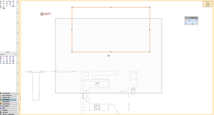
Edit the crop of the viewport and see if there's a crop object.
Horizontal Section Viewports have no X, Y extents but they can be cropped. This is similar to how Top/Plan viewports work.
Thanks Matt
I hoped the screen dumps (SD) would be sufficient to show that the crop object is unable to view the relevant area. Also the issue can arise when the viewport is first made, the third viewport seems to have been constrained at a section line!
In this case I was able to get another HSVP to work, and to crop it successfully.
I am still puzzling how the "instance" option works (esp for HSVP)...
-
Another file ...another inadequate HSVP !
-
Hi
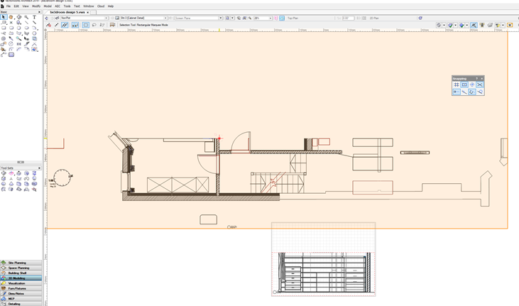
I am having some challenges with these...on frequent occasions I have set one up and the viewport does not cover the full area of what I intended.
To resolve the issue I would expect to find a horizontal section marker line that i could adjust to ensure the section covered is what I am looking, however it seems these are not visible unless they created in another viewport. Is this case? and if it is the case why doesn't the Viewport OIP allow you to manage instances of it, as it does standard Section VPs?
Now I have a file in which the viewport "lost" the area of view after I moved its location on the sheet ( and this was the second attempt to create the viewport over the relevant area.... how could that just happen?
Anyone point out what i am missing here?
TIA
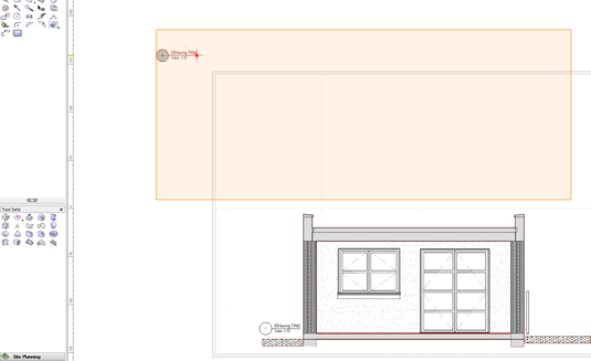
viewport position on the sheet
view port clip object....note area of view/interest not showing in spite of correct layer/class set ups.
Thanks
Bob S
VW Architect 2019 on a Win10 pc
-
-
1 hour ago, Matt Panzer said:
In render modes that do not show hatches, the fill color is shown instead. If you edit the attributes of the class used for the component, you'll see it's using a hatch, however, if you change the fill to solid, you'll see that it does has a megenta color. Set the color as desired, then change the fill back to hatch and you should see that component in the new color.
Thanks @Matt Panzer Helpful
What I am struggling with is the disconnect between display of wall styles in Top/plan view and section/3d views.
Is it really the case that a wall style build up only shows on WF TOP/Plan view and does not show in section views or have I missed something?
TIA
-
Hi Matt
Here you are I/ve worked on it some more as I investigate surface hatches and textures (the issue is still apparent on the four blocks that remain as the same wall style) ....while you are looking can you explain what settings gives rise to the pink fill for the conc. blockwork...it doesn't seem to come from the class settings.
-
Hi
This seems to be a glitch, has it been spotted ? is it just me? Should I take it personally?🤔
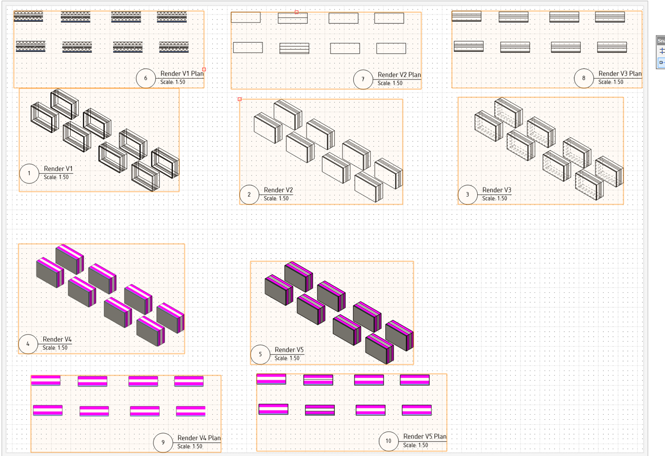
I am carrying out a test so I can be sure I understand how changes I make to a wall style will be represented in different views( top/plan, top, iso) and rendering modes (wireframe, hidden, hidden-dashed, open gl, opengl +hidden foreground). I created 8 sections of the same wall style on a design layer, then created 5 pairs of viewports within a sheet layer.

The issue in drawings 7 is obvious but also shows in drawing 10 (OpenGL +hidden line FG)...two blocks are displaying differently from the rest of the set.
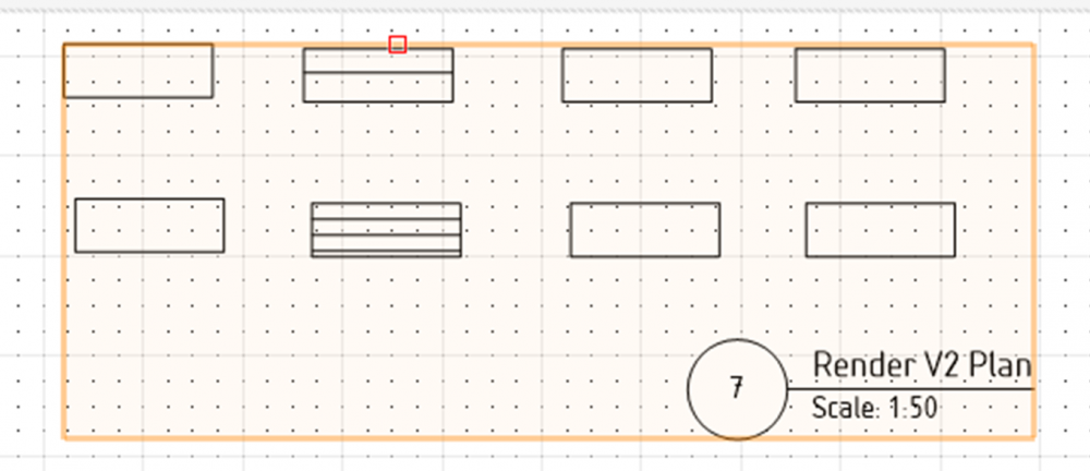
To confirm all the wall segments are the same, and I have tried moving them about within the design layer...it is always these two positions that show the inconsistency, so it must be down to the HL rendering mode. Anyone know what's going on?
While I am here can some one point me to resources/explanations how to (or why I cant) get the hatch information shown on the top/plan view of the walls to display with other rendering modes.
Thanks
Bob S
I am using VW Architect 2019 on PC
-
Both helpful contributions to add to my learning curve....thank you.
I can see these will be a good starting point and deffo helped with understanding the options.
I'm sure there will be situations (eg staircases and landings ) where I'll have to make a model that has 3d polygons act as the "finish/texture" plane but at least I have a sense of the options.
-
Thanks
Helpful information and a useful workflow.
Your approach works well unless you want to range of different tones up the wall.
I am used to using VW for building/architecture, whereas my latest work is veering to towards small scale interiors and bespoke carpentry...which present slightly different challenges, that I'm investigating how VW can be used to resolve them.
-
On 5/3/2018 at 11:28 PM, AlanW said:
Unless there is a better way to have multiple colours for rooms i would like to hear it.
Hi
I came across this thread as I was facing the same challange, how to control surface colours within an interior design project.
I discovered and this thread confirms
i) when using wall styles, use class fill to colour a component - but this impacts how the element looks in section views, and prevents different surface colours for the same wall style
ii) do not use wall styles and 'texture' each wall and surface within the object info palette - say goodbye to wall styles!
iii) create a surface polygon of each wall and show correct texture/colour - not nice as changing wall layouts require these "surfaces" to be amended !
Given the quote above is 3 years old are these still the best options or has a better way been created/found?
TIA
Bob
-
Thank you ....very helpful... as was your drawing title block info on your web site!
One of those situations where I have an idea what's going on but unclear what is the principal method of control !
-
 1
1
-
-
Hope its ok to gate crash here (I realise its a spotlight thread)...but this thread seems to be covering what I am experiencing.
I've been getting used to VW2019 (Architecture) and been puzzling about the impact of light fittings on my openGL renderings. I have a simple model of a kitchen design, inserted a VW cooker hood symbol and the rendering on the modelling went seriously dark to show the impact of lights within the symbol. Is this standard? Can someone explain what happened ?
I tried turning off the display lights but that didn't seem to work so I just added a heliodon to the model but that casts shadows/shade. Do I need to add several more to get an even colour tone on my different elevation views (something I've seen Jonathan Reeves do on Youtube to get architectural shadows), or is there a way to have a default light level as seems to be discussed in the thread?
TIA
Bob
-
Hi
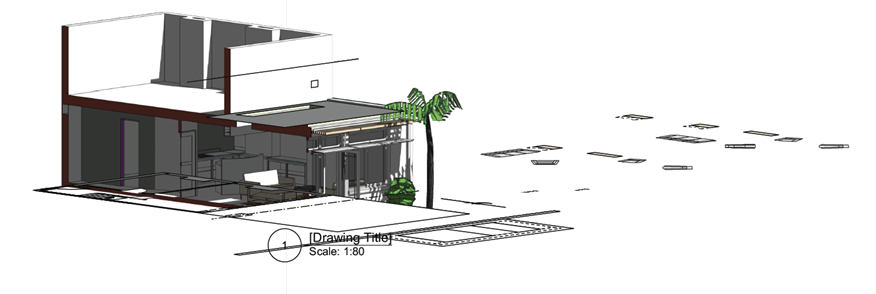
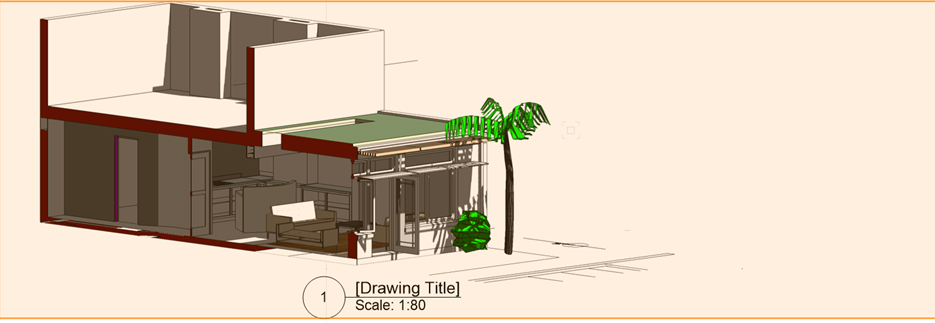
I am looking to show the benefit of solar shading for a small domestic project, by creating a solar animations of a clip cubed axo of the interior, with and without solar shades. However the resulting animation does not show the shading of the clipped elements, even though that is how it looks as the animation is built.
I know that there is a toggle for this feature in the section view ports but cannot see where i would ensure this is on with a clip cube in a design layer.
What trick am I missing here?
-
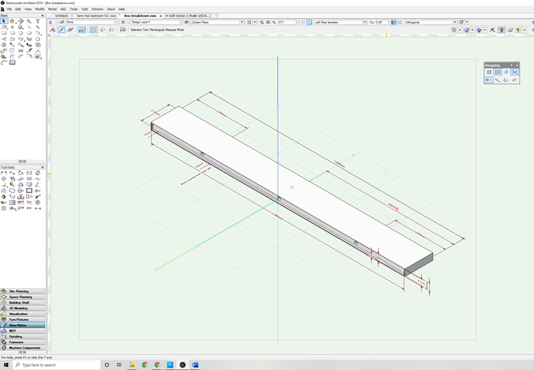
Hi
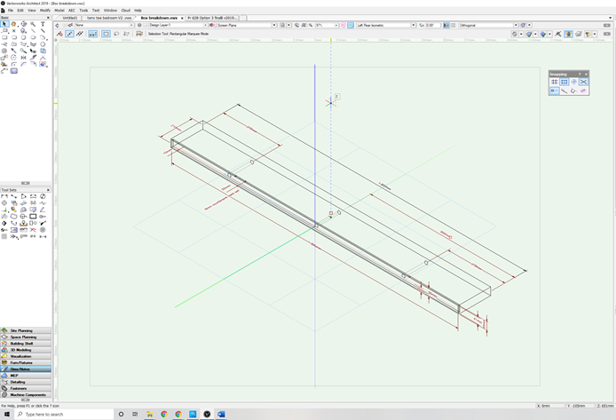
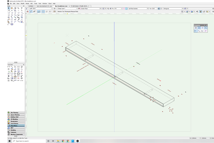
Had a good look, here and on line, for help on this but have not found a solution.
I wanted to create a dimensioned iso projection of this shelf item, the dimensions do not display when I render in dashed hidden line...the view that properly explains the item.Am I missing something here, is it an ongoing story, or has this been solved in a more recent version of VW?
Screen grabs of dashed hidden line, wireframe view and open gl views below.Thanks in Advance
Bob
VW2019 on Windows10 - i5 processor - 8g ram


-
Hi
Long time user of VW, and now working with Architect 2019 on a pc.
My puzzle relates to errors I get printing OpenGL images of a clip cube axo to PDF.
The PDF errors I am dealing with include;-
- elements that are not in range of the clip cube are shown
- 2d elements are not properly clipped by the cube
- 2d floor plan elements overlay and obscure the 3d objects
I have tried both printing and exporting the sheet file.
Is this an acrobat or VW issue? (FWIW I'm using Acrobat 8 )
Is the work around to avoid 2d elements with a model? (Some thing I'd want to avoid given the flexibility it offers)
I'm aware of the transparency issues and wonder if there is a knowledge piece that covers the issues with VW and PDF.
Thanks in advance
Bob

-
23 hours ago, BobS_50 said:
Hi
What do you have available if anything for PC with windows 10
thanks
Bob
@Phil my email is bob.seddon@ardpm.co.uk
Tvm
-
Hi
What do you have available if anything for PC with windows 10
thanks
Bob
-
Interersted in details on these licenses pls email Bob.Seddon@ardpm.co.uk


Using 3D image Files from Furniture Suppliers
in Troubleshooting
Posted
That worked for me until 3DWarehouse stopped having 2018 versions of the models !!