


Mickey
-
Posts
527 -
Joined
-
Last visited
Content Type
Profiles
Forums
Events
Articles
Marionette
Store
Posts posted by Mickey
-
-
This is one of my "I hate Braceworks" moments.
I'm trying to learn to live it, but it keeps making my life worse not better.
So maybe someone can help a couple of items I keep running into.
Scenario #1
I have drawn some trusses using Tomcat. In this case a bunch of plated 12". The vendor chosen owns XSF so I want to change the symbols in the configuration to XSF so I can see where beams and things line up. If I were using the weight calculation tools this would matter as well, but currently not.
When I open the Replace Truss Configuration tool I'm presented with a lot of options and it shows me all kinds of lengths, but no mention of symbol.
See attached. - Or actually not because I keep getting a server error with upload failed.
Scenario #2
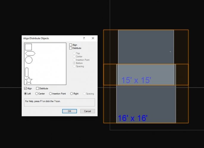
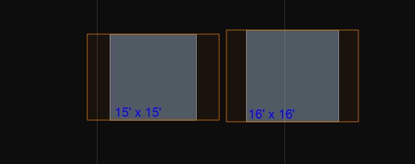
Very similar to above but not symbol specific. I have drawn some truss with 12" and want to replace it with 20". Again I can see options in the change configuration.
In the case of the photo you can't see there are 2 2'. Is one of those 20" and one 12" ? Where did this 2'6" truss come from?
In the old days I could simply "replace symbol" but there's no option for that.
I respect what Braceworks is trying to do, but it is not making my life better instead it makes it much worse.
Thanks for any help.
-
 2
2
-
-
This stupid dialog has come back to bite me again.
Using 12" truss instead of 20" this time, and getting the same ridiculous truss cross pop up.
I hate braceworks so much it makes me sick to my stomach.
It's infuriating how much harder it has made using the truss tools.
-
1
-
-
I just got burned by these in 12" truss. I had done something to my symbols in 20" to make them go away.
I F&(K!NG HATE BRACEWORKS
-
It's a folder on my hard drive, and it's only this file.
I have lots of files I work out of on the same hard drive, same folder hierarchy within the one drive folder.
To me it's not a onedrive thing. It's a VW thing related to this specific file.
-
I have a file, and it seems to be specific to this file, that occasionally when I save I get some kind of failed error message.
See attached.
If I Save As, and select the file I'm working on it saves over it no problem.
There's plenty of room on the drive.
I save a new version almost every day.
This is saving to my local hard drive in my One Drive folder specific to this project.
Again it's only this file. I have other files for this project in the same folder, or sub folders that do not have this issue.
This 21 I have not switched to 22 yet.
-
4 hours ago, klinzey said:
Yes it should work fine with any student version.
Make sure if you are converting the file from an older version you save the file after it gets converted.
The file must exist on the disk in order for the data exchange to work.
Thanks
I'll dig deeper
-
First does lightwright data exchange work with student versions?
Second does lightwright data exchange work with a watermarked version?
I'm trying to help someone with a show, and the file was created in a student version which creates a watermarked file.
It has a light plot already drawn.
I tried connecting the file to lightwright, but it doesn't import anything into said lightwright.
Before I start chasing my tail I want to know if it is supposed to work.
-
Please see below images for how this new "feature" ruins my workflow.
Image 1
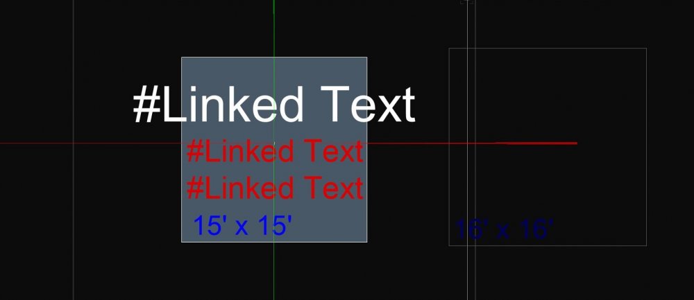
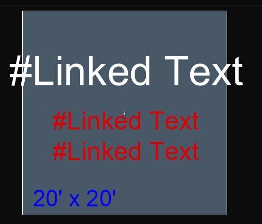
Edited the object you can see the different fields as "#Linked Text"
The white letter format is larger than the symbol.
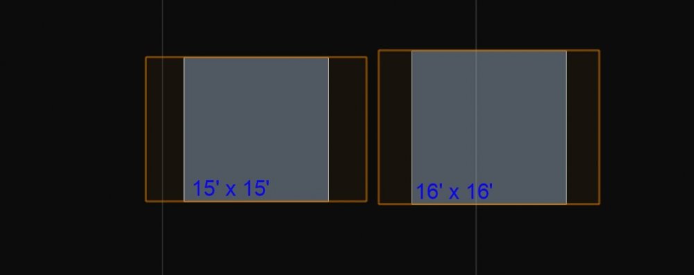
In this case the text field will be filled in as a 3 digit number which is this booths number.
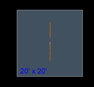
Image 2 are 2 different symbols selected, and even thought there is no value assigned hence no visible number the selection box is larger than the symbol because the invisible "linked text" field is larger than the symbol.
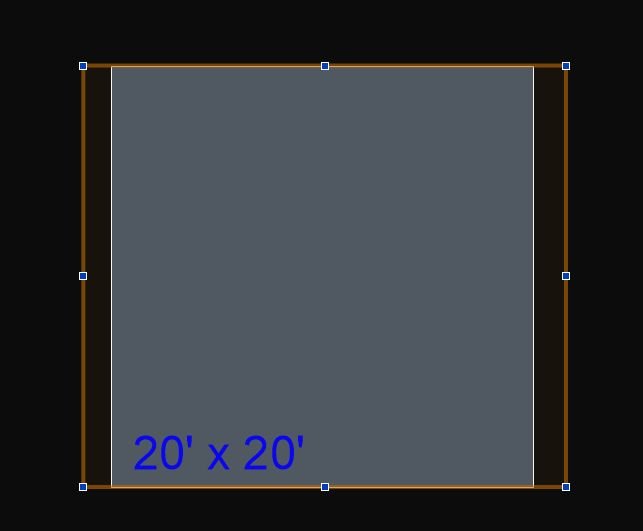
Image 3 both symbols aligned left, and it aligns the invisible linked text field, and not the actual edge of the symbol.
This is not a feature, this is someone creating value by changing things that weren't broken, and breaking them.
The law of unintended consequences?
Please fix this. It's really making my work unhappy.
I'm going to submit this as a bug.
-
Does anyone have this issue or is it just me?
-
Nemetchek why do you continuously make my life more difficult?
Please see attached screen grabs one from VW 2020 and the others from 2021.
I have a lot of simple symbols with custom text fields, and record formats.
In this case these are symbols for a trade show style booth layout.
So booth number, and 2 different booth names with text formatting.
In 2020 the linked text would be just a slim invisible object that you have to draw a marquee around to order to find.
In the Text 2020 jpeg here's a symbol being edited in 2D, and you can see the 3 linked text objects
Yeah sometimes it can be tricky to find, but at least it's contained within the boundary of the symbol.
In the link text 21 jpeg you can see the words"#Linked Text" but with my formatting those words are bigger than the symbol.
Look at the symbol 21 jpeg and you can see the boundary of the symbol is now larger than the symbol itself, and this really messes with my ability to line objects up.
Center is not center anymore.
Is this a feature or a bug?
-
1
-
-
@JustinVH You bring up an interesting point.
In a 5 way corner what is "top"
This might explain some of the cussing I was doing at VW while trying to build a simple 4 post truss box around a stage.
Using the insert truss tool I had placed a 10' stick as a leg vertically, and when trying to insert the corner block it kept putting it on the bottom of the leg and not the top.
I had to manually move it, then it all of the various pieces I attached using the insert truss tool where sideways not top and bottom.
A simple 30'x30' box with 4 legs should have taken 30 seconds to a minute to build using the insert truss tool, and instead it took me a half hour part of which was fighting the anomaly we see here.
It seems the VW truss tools have gotten more complicated than useful.
How would I set a 5 way corner so the open end is on top, or on the side if the corner was part of a larger system?
-
Thanks Tom,
That's something that needs to be fixed in the Tomcat library.
This must be some new feature because I've never seen this before.
Did you just check the unchecked box, and fill in the XYZ based on the top?
I'd like to know in case I see this again
-
What is this crap and how do I get rid of it?
See attached pic and file
I tried using an existing symbol in my library and a newly imported symbol from Tomcat.
I placed the corner block using the insert truss tool from a front view to stack it on top of a 10 vertical piece these data tags became visible.
When selected they show up in OIP as a Truss Cross.
There's no class associated with them.
So I deleted them, only to have them come back when I nudged the whole truss piece
WTF is this crap?
A new "tool" that I didn't ask for?
Why Why Why Vectorworks do you make my life so miserable?
Anyone know how to get rid of them?
Thanks
-mickey

-
On 4/29/2021 at 10:12 AM, Matt Hall said:
What is the best way to use project sharing over the internet?
One of the groups I work with has had a lot of success using Dropbox.
Some "gotcha's" you have to look for (at least in a pre pandemic word)
Always check out your layers before getting on the plane and turn off your wifi on the plane while working with your file.
- Even if the plane has wifi it may not be fast enough to sync to the xml file, and you could end up with a broken working file that has been disconnected from the project file.
- If that happens you have to create a new project file, and users have to create new working files which could strand some changes
If you work on both a desktop and a laptop create separate working files for each machine. The issue of a working file becoming disconnected from a project file can happen.
Make sure everyone on the project is using the desktop app, and working out of the file in the Dropbox folder.
- Yes there are people that still don't know how to use Dropbox
Otherwise we've had a lot of success using project files assuming the users know how to use project files.
That said we created a document outlining best practices, and guidelines to help new to project files not screw up the classes and layers.
-
I figured it out.
I had a long call with Tech Support and we deleted Vectorworks 21 preferences folder.
In Windows 10 that's in User/AppData/Roaming/Nemetcheck/Vectorworks/2021
Deleted the whole folder which makes you re-activate VW.
We noticed the palettes were correct.
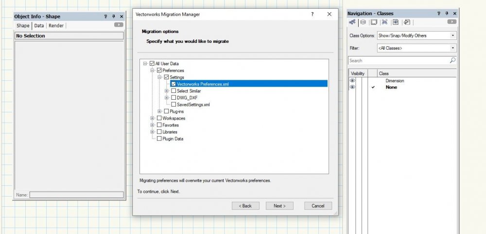
I ran the migration manager again, and that's what broke it.
After many many attempts I narrowed it down to 1 single checkbox that breaks the palettes apart.
Preferences.xml
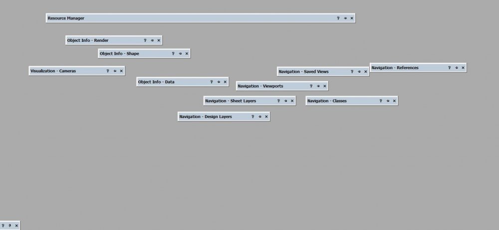
You can see in the images below what happens when that single box is checked.
I ran it again, with everything checked EXCEPT that 1 box, and it works.
I'll submit a bug report
So glad to be doing product development for something I pay for.
-
1
-
-
I uninstalled and re-installed after doing a registry clean.
Nothing changed.
As an extra ha ha bonus when I edit a workspace and come out of it any window and pallet placement I've done is lost.
I'm so glad I pay for a subscription of Designer.
I can see my money is going towards useful, and meaningful upgrades to the platform
Oh and Support has not responded to my request.
I'll be calling tomorrow
-
2 hours ago, LarryO said:
I had these blank palettes too. Mine were hiding off at the very right side edge of my monitor. That was VW2021 before any service packs came out. So it was one of the issues that prompted us to delay installation until SP3. I've have seen the again but they are not as predictable.
My small beef now is that when the tabs are merged as per previous years the tab at the far right in the palette becomes the active tab when ever the palette is reopened. The palette doesn't save the active tab when closing.
OK great. I'm not the only one.
That's a small win.
Yes same issue with them all being on the far right of my my right side monitor.
I updated the graphics driver just in case, but that didn't fix it.
This was a pre SP3 installation but I didn't use 21 until very recently.
I had no need to draw anything as I'm in the entertainment industry, but now I've got a gig, and we're working in 21 so I updated to SP3.1 and this.
Laptop looks fine even with 2 monitors, but it was a clean 3.1 installation.
I guess I'll try uninstalling, and installing a fresh 3.1
How Lame
-
I guess no one has had this issue and I'll be calling tech support where I'm sure they will tell me they've never seen anything like this before
again
-
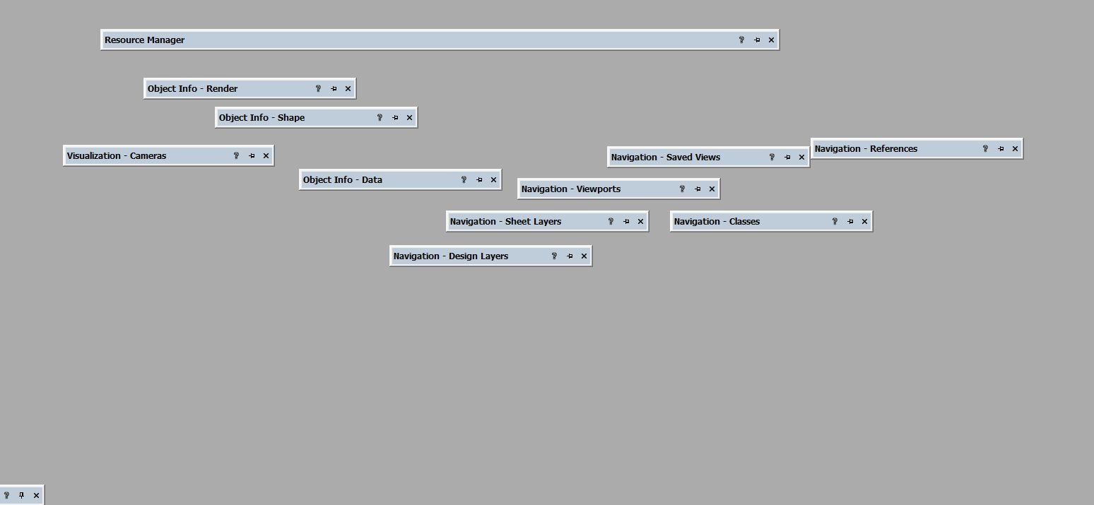
Attached are 2 screen shots.
VW2020 and how window palettes used to, and should behave, and VW2021 SP3.1 and how they look now.
I've restarted the computer to see if that would help, and still wrong.
This did not happen on my laptop. Only the desktop version, and only after installing 3.1
Anyone?


-
On 3/13/2016 at 4:26 PM, scottmoore said:
That said, here is a thought:
Create your version of the fixture and use an actual "lens" image texture for each of the LED "pixels". Make sure the texture is set to "Glow" and that the image will receive it's color from the class color. Make sure the lens part of your fixture is assigned to the Spotlight "lens" class. Also, Make sure you have your Spotlight preferences set to allow the lens color to change color based on the selected color in the fixture. I have added a clip denoting those preferences. Note that the class name for mine is specific to my company's template file. Yours will be different.
Attached is an image of a pair of Source Four PAR fixtures from our library; one Narrow and one Medium. The lenses add a touch of realism without slowing down the render process, or at least, not to a point where I can tell.
This thread is 5 years old, and here I am wanting to see the sources of lights I'm trying to render.
I don't see the files, or images listed, probably because the thread is so old.
Scott can you share again?
Has there been a newer and better method to see the sources or dots?
Thanks
-mickey
-
It's not a super easy transition and Import.
I think it's odd that the set design team is being asked to import into MA3D.
That's usually the lighting department importing the models from the set department.
Here's a link to some info
https://support.actlighting.com/knowledgeBase/11589471
Good luck
-
2 hours ago, bcd said:
I believe there's a Marionette floating about to automatically generate 3d map from a 2d image.
Can you expand on that thought?
Link to something maybe?
-
29 minutes ago, Kevin Allen said:
Ai and VWX both have Trace Bitmap functions.
OK I did a search in Help and found the tool.
There's very little information about how to use it, and what the numbers mean, but I kind of got it to work.
It looks like it's very sensitive to how the image file is imported.
Once I slap it around a little I think it will reveal its secrects
It would be nice if VW would offer some deeper explanation of what the numbers mean.
This is not the only example of that.
But this method is going to be way better than what I was doing before
-
I am trying to make some 3D musical notes.
I am working with a visual artist on a project, and I need to do some modeling that has physical musical notes.
I found some shared vector graphics, and opened those in Illustrator, exported them as DXF files, imported each one to an individual VWX file, made a surface, and extruded them
Yeah me!
The artist didn't like the musical notes I found, and has instead drawn new ones
Boo me
I went through this earlier in the project where we wanted a heart.
I took the PNG file dumped it in VW then used a series of arcs to re create the shape, made a surface out of them, and extruded. Woo-Hoo heart.
But the thought of having to that gag for 4 different complex musical notes has me rethinking my approach.
I'm pretty certain that I'm using the wrong software to do this. I bet there's something out there that could take a PNG, trace it, then extrude, and model it on an iPad, but I don't want to buy, and learn a new modeling program just for this small project.
There has to be a better way.
Doesn't there?
Thanks in advance
-mickey


Replace a truss symbol in a configuration
in Entertainment
Posted
Thank You Andrew for making my point
Although I have often thought of myself as "Low-Life" I've never been "Low-Level"
🙂
But I do play around with truss shapes a lot, and what used to be a simple process is now so bloated and frustrating I find myself not using the Insert Truss tool, and just using symbols.
Right now I've got a bunch of truss towers that are more complex than straight sticks.
I need to switch them out for black truss instead of silver.
Oh how sad am I that I can't just click the OIP and replace symbol.
No instead I have to go through this inventory stupidity.
Why do I care about an inventory?
I'm not in a venue, or a rental shop?
I just want to be able to run a report and count all my pieces.
But Braceworks has made that almost impossible.
I'm going to try what Jesse has proposed, but I will likely give up once I'm frothing at the mouth in anger.
again