mgebel
-
Posts
29 -
Joined
-
Last visited
2 Followers


-
InteriorCAD record formats
mgebel replied to mgebel's topic in 3rd Party Services, Products and Events
Hi. I seriously need help with RECORD FORMATS! The specific case I'm looking to figure out is with using InteriorCAD objects, but I imagine this applies to other workflows and objects in Vectorworks, as well. I haven't been able to track down any generalized discussion of what are record formats, what do they do, how they work, and how to create one. If anyone knows of a resource on the internet that has some decent nuggets, I would be much obliged!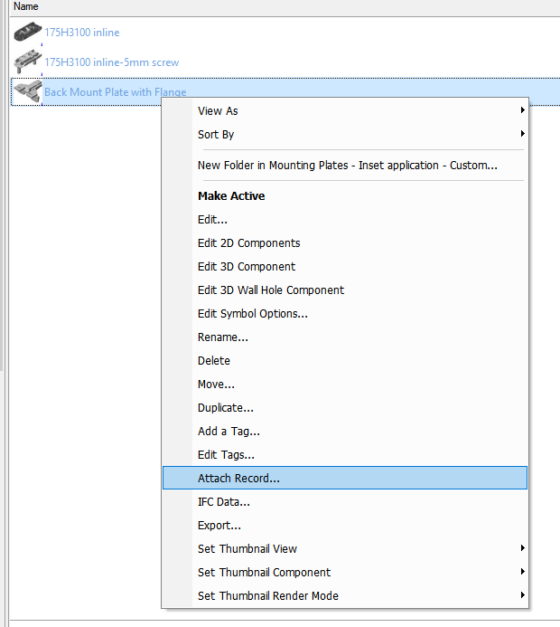
-
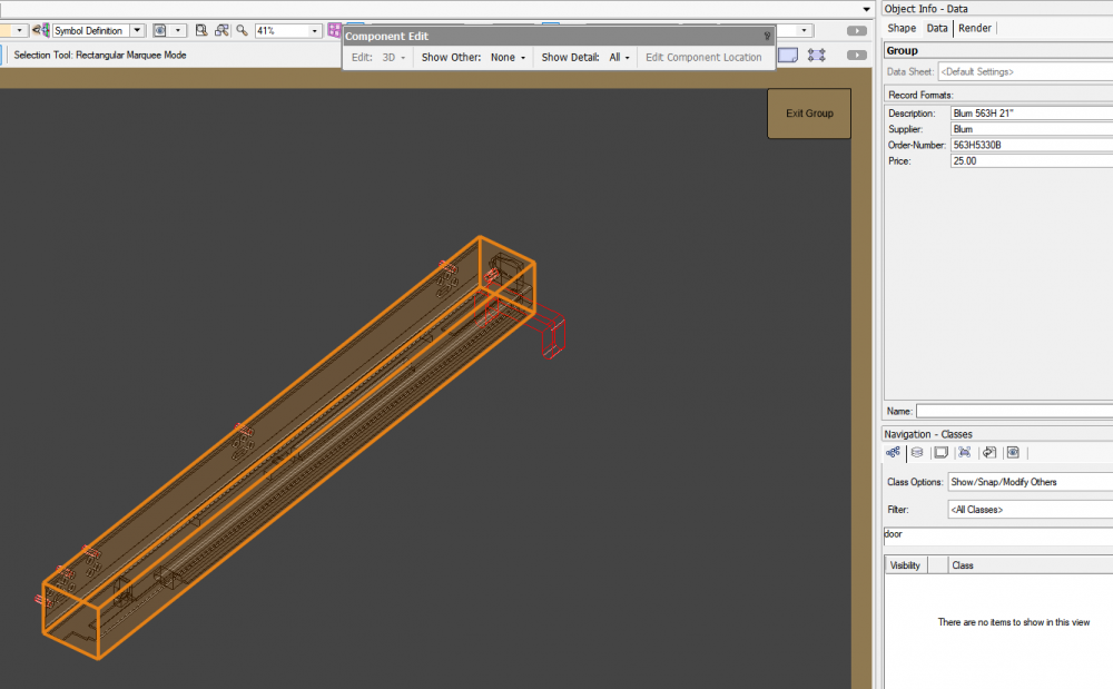
Hi, I had previously set up a set of undermount slider fittings in VW 2020 using the standard method outlined in the InteriorCAD manual, and they continue to work just fine. I remember vaguely that I had a difficult time locating where was the right place to find the record format inside the symbol. Now I am trying to set up some variations, and I can't locate the record format, or else if I do, all the fields are zeroed out. according to the manual, it should be located on the main group of geometry in the symbol definition, but it's only showing the "sales info" records. However, when I place this slider into a cabinet, it correctly applies the records to the drawer box. Is there any other way to access the records for these fittings? I tried rebuilding from the default example fitting, but I can't find the records for that, either. Thank you!
-
Interiorcad for smal businesses
mgebel replied to Walter_J's topic in 3rd Party Services, Products and Events
Hello, I've been using InteriorCAD for about 2 years, and I have very little experience in Fusion360, Solidworks, Inventor, etc, but I'm familiar with how they work. InteriorCAD is designed to be a dedicated parametric solution for cabinet manufacturing, but it can be adapted to work for any sheet-good cnc based manufacturing (metal, glass, stone, composites, etc). From my understanding, the 3d modeling environment of interiorcad is more like a hybrid CAM platform. When modeling parts using solid subtraction, you are in fact creating toolpaths (i.e. contours, dados, rabbets, drillings, etc). These are smart objects that are parametrically driven by the parts they are attached to. The advantage here is that you can effectively skip the CAM programming step and go straight from modeling IC objects in the design layer to your CNC machine, assuming all layers and tools and machine settings are programmed correctly. However, if you are interested in an automated solution for nesting and labeling, you will need a standalone program like Cutrite or another optimizer. There are many standard fittings (blum, hettich, etc), but in my experience you will need to make many of your own depending on what global market and what type of hardware you typically use. This is not difficult to do in most cases. If you are looking to compare InteriorCAD to other similarly classed programs, I would look at something like Microvellum or Wood CAD/CAM. Both of these operate using similar principles with similar quasi-CAM modeling project workflows, but they are based on AutoCAD. I have a Colleague who works in Wood CAD/CAM and uses Cutrite for nesting and labeling. I have been able to send him DXF files that are indistinguishable from the output of his programs, however, he has pointed out several key features in Wood CAD/CAM that are lacking in IC... It seems reasonable that these features/capabilities could be integrated to IC eventually... IC does have some useful 2d Part Layout tools, but they can be painful to use at times. I would love to see some additional development added to this feature. As it stands, the part layout objects work somewhat similar to viewports, but there is no way to edit (add/remove/relink) objects to an existing part layout... I would love to see a new tab in the navigation pallete that lists all of the cabinet objects/custom parts in the project for direct part layout creation and editing... I would absolutely recommend IC for anyone working in VW who does flatbed CNC cabinet fabrication, but I would not discount the benefit of maintaining a workflow in Fusion or Solid works (or masterCAM or other 3d CAM software). In particular, if you are using any parts that utilize 5- or 6-axis milling, you will need something with a little more horsepower to generate 3d toolpaths. Hope that helps, and good luck. M -
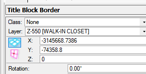
Hi. I encountered this problem when upgrading from 2020 to 2021. On sheet layers that were already set up with titleblocks, the titleblock shifted very far from the page center, even though the object info indicated the titleblock was centered at 0:0. These snaps show the titleblock object having been manually moved back to the page center, but with the x:y coordinates indicating 3+million inches away. Anyway else experience this? Anyone know of any fixes?

-
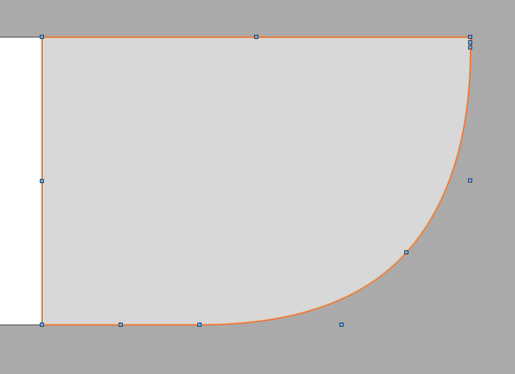
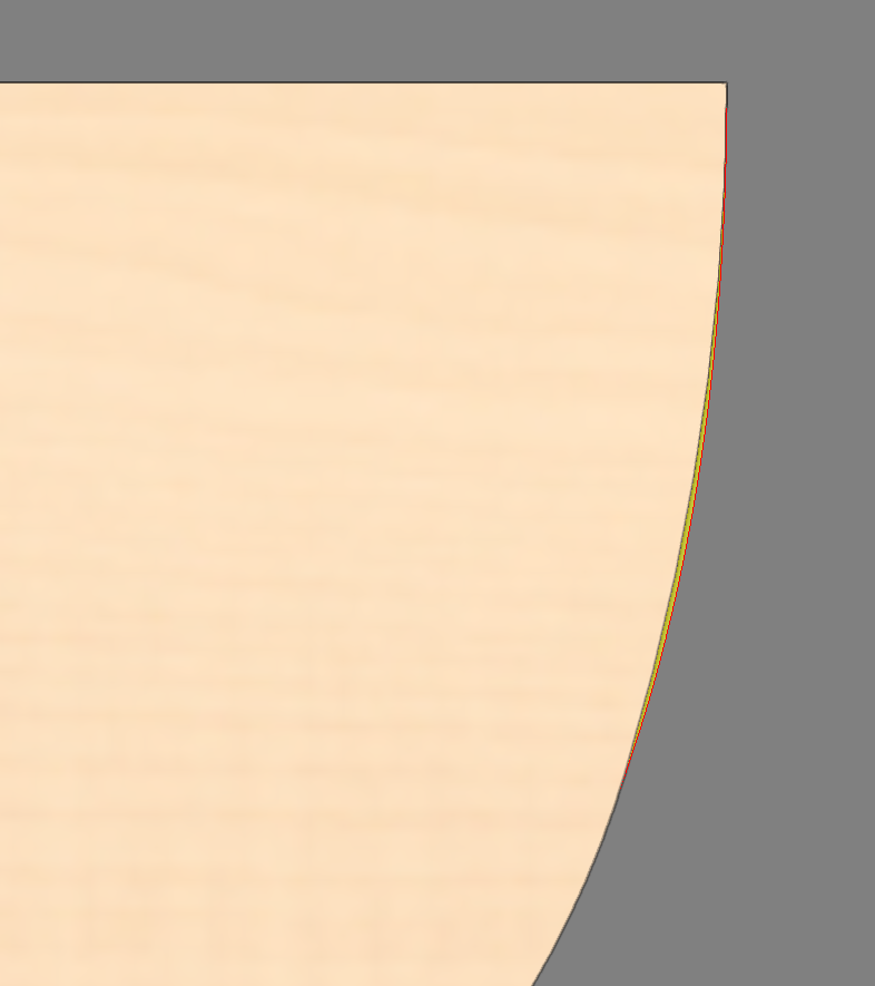
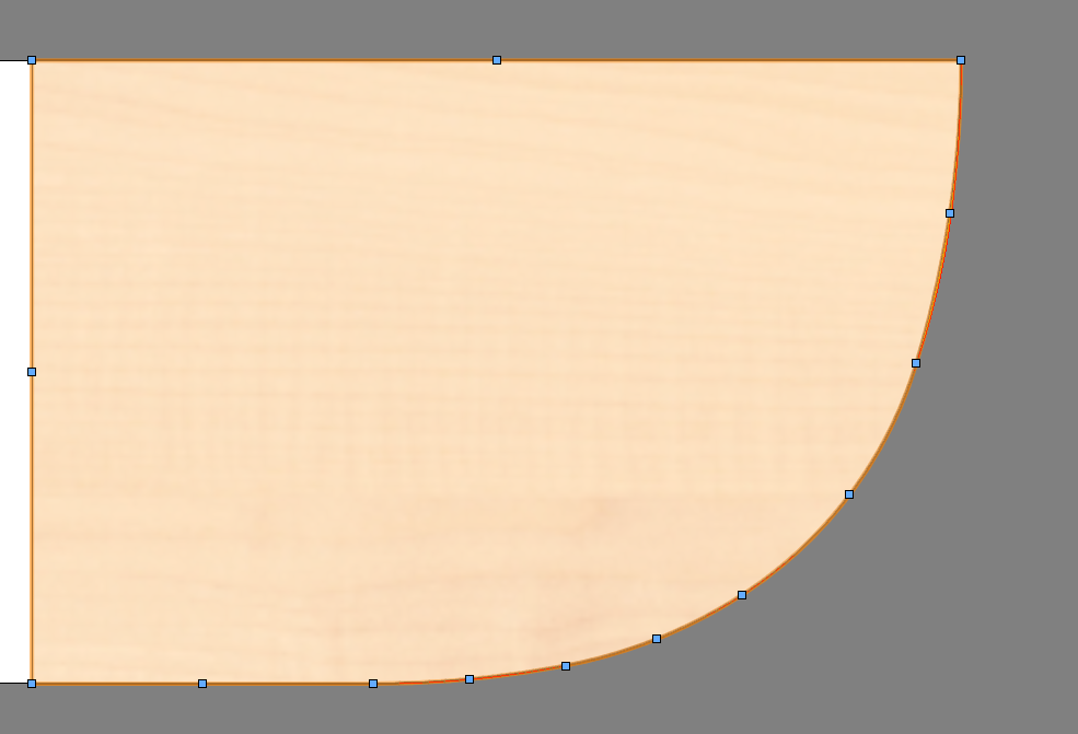
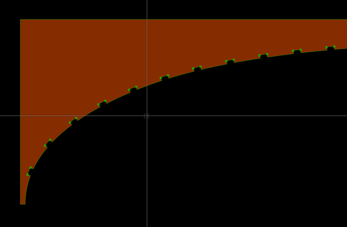
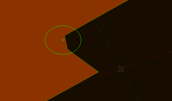
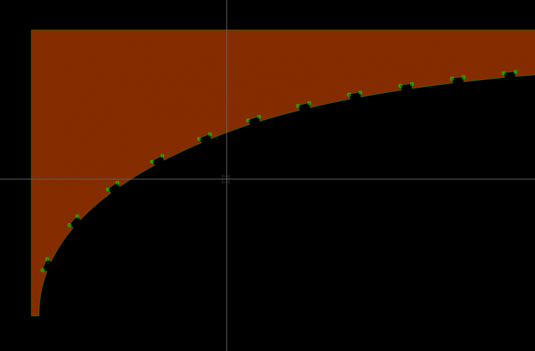
I'm replying to this again, because while it continues to be an issue, I have achieved a bit more clarity about what's happening. Also, I have begun to use InteriorCAD to generate my DXF's, which seems to resolve most of the geometry errors natively within VW that previously came up when directly exporting VW geometry into DXF.. In my latest project, I am designing a bed around the client's existing mattress, which has an irregular curvature at the end. I carefully templated the corner radius, then scanned in the template on a flatbed scanner, then traced on the scanned image with a polyline. So far so good. Only, once I convert the polyline to a custom part, it drops the bezier function from the polyline and converts to a series of arcs, instead. This is the original source geometry. And this is the custom part on top of the same geometry. The yellow wedge that is poking out on the right side is the difference between the two shapes. I have tried several times to fit, but while close, it's not perfect. For this project, it's not so critical with small differences as long as I adjust the surrounding parts to fit the new curve, but in other projects that I've done done recently, when the parts came back from the router, they don't actually fit together as designed, which resulted in a bit of frustration. Here you can see that the reshape handles are no longer bezier, but now all arcs: I am assuming that the InteriorCAD algorithm is dropping the bezier due to the lack of universal support for bezier curves in many WOPs? or is it a lack of support in the dxf conversion? I think that my solution will have to be to fit any scanned in curves with arcs rather than beziers, but I am hoping that there is a workaround for this? maybe @Stephan Moenninghoff might be able to shed some light on the underlying principle? Thanks!


-
Interiorcad beginner questions
mgebel replied to michaelk's topic in 3rd Party Services, Products and Events
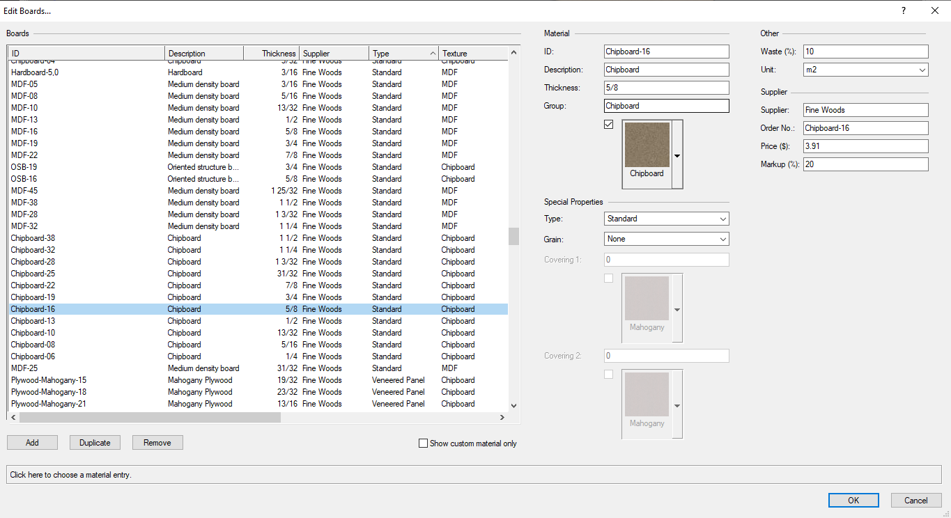
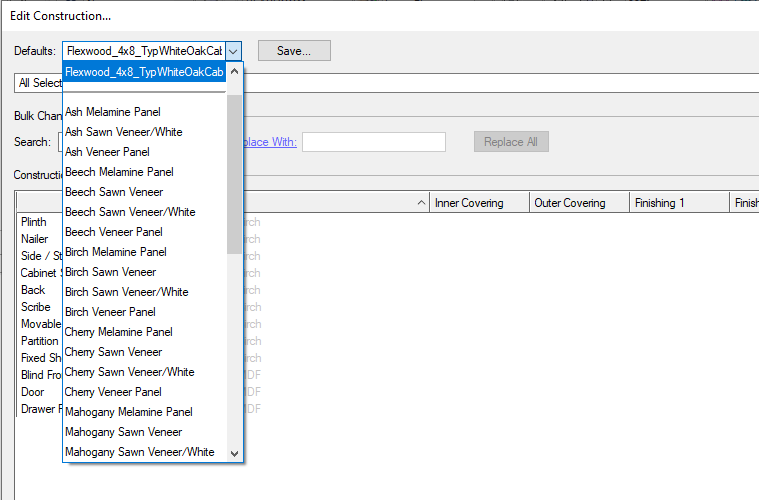
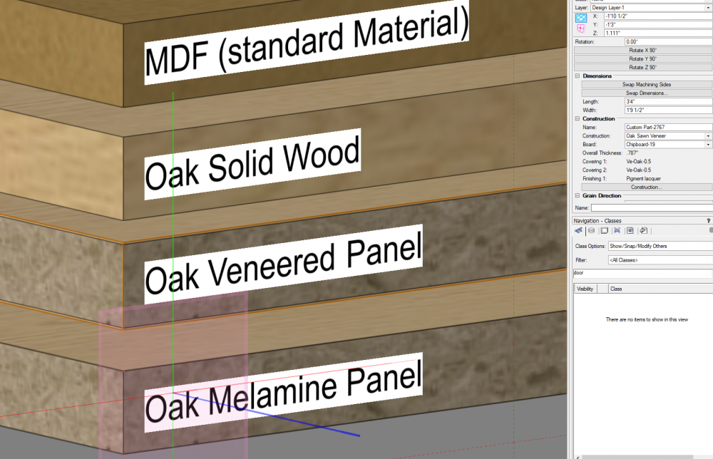
We have been using InteriorCAD for about a year now, and getting the hang of implementing board types. It's not always intuitive what the right type of board is, because the various types are very much focused on production (good for me!), but it's probably a bit cumbersome for designers. If you want a texture added to a material without fussing about coverings, finishes, or edge banding, I recommend going with a Standard Panel defined by whatever the core texture is. This will display your desired texture on edges and all faces with or without 3d details turned on - and that saves on RAM, too, since VW won't be rendering any extra geometry.. Veneered Panels: If you want to be more realistic with the rendering, then you can use a veneered panel and choose the covering of any thickness on the front and back faces, as well as the texture of all the edging (this is useful for both veneered panels, as well as high-pressure laminate panels). Melamine face panels: have different covering and substrate textures, but the covering thickness is effectively zero. This is a nice option for many applications, because VW doesn't easily allow one to select different textures for individual faces of generic solids. Note: using this a "melamine faced" board type does not mean that you are specifying melamine for your project! It only means that you are defining the board by the overall thickness of the panel, without adding any covering thickness. While you can change the finishing and edging on melamine-faced parts, you cannot change the covering without creating a new board. If you want to change the texture of an individual part or in a set, than you can do so by adding a "finishing," which can be any RW texture. (*this is also true for standard and veneered panels) Solid Wood: Allows one texture to be displayed throughout, and also allows the thickness of individual parts to be more easily changed. Again, using this option doesn't mean that you are specifying solid wood. I use this material type for metal, as well, and I can send these parts out to my metal fabricator to be waterjet or laser cut. Glass: same as above. Once you have a board set up with your desired texture, you'll want to create a set with all of your boards and edges specified for every type of cabinet part. Then if you want to change from one texture to another, you can just change the construction set and everything in the cabinet will update. The more accurately you define the IC materials according to your real-world materials, the more accurate the model will be. Most shops will deal primarily with one type of material or another, and everyone is going to have their preferred workflow, so be sure to check with your fabricator if you plan on exporting parts to them! In my experience, the more time that you spend setting up the libraries and saved sets, the more time you will save in the drafting process. The difficult part is understanding the nomenclature, but once you get past that, it's fairly intuitive.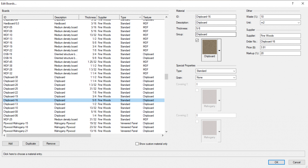
-
New problems outputting PDF files via Publish or Export
mgebel replied to Matt Hunt's question in Troubleshooting
Just tried again after re-setting the page size of the sheet layer from Arch D to 36 x 24, and got this as the published pdf page size:
-
New problems outputting PDF files via Publish or Export
mgebel replied to Matt Hunt's question in Troubleshooting
I'm having this problem, too. Everything from top to bottom is set to ARCH D, nothing outside page boundary, and when the PDF opens, the page size is different almost every time: The following is a screen grab from Adobe Acrobat.. it should be 36 x 24. I've had different random values for this after trying to change some parameters, but never an even dimension corresponding to any standard defined page size.
-
Just read this and thought I would chime in, as I'm modeling a project with an architect in Revit, and we have been able to send the project back-and-forth with some success. There have been some weird things happening, though, and I'm curious if anyone has encountered something similar before. 1) we get the building shell from the Architect as IFC. All geometry comes in to VW cleanly, and layers and classes map nicely. However, everything is coming in rotated about the origin by exactly 17degrees. We did a screenshare to check that his model was not rotated, and we couldn't find anywhere this odd rotation was coming from. The solution is to simply rotate all of the Revit IFC geometry -17deg every time we update the reference... annoying, but not a deal breaker. Also, textures are stripped out, but some colors come through for example, none of the glass has transparency. This is a just a bit annoying. Should IFC support textures? 2) we are modeling interior elements (mainly millwork), and sending back to the architect. We tried a large variety of export formats (not SAT, though). Nearly all of the formats we exported came into Revit with triangulated faces. In the end, we decided to go with Rhino .3dm, which translated all the geometry very cleanly, but completely stripped out all the textures and color. 3) At that point, we stopped, because we are achieving what we needed to in terms of geometry. I would be interested to know if anyone has had any more success going back and forth with Revit, while maintaining textures in both directions?
-
Clip Cube shortcut key has different behavior than menu command
mgebel posted a question in Troubleshooting
Hi. Way back when I was first getting started with VW (last year), I setup a shortcut for clipcube (control+shift+C), because I like to use it quite often. However, I did not realize that there was something wrong with the behavior until recently when a colleague explained the way that it is supposed to work. Normal behavior: When you select an object and choose the Clipcube command from either the view menu or the toolbar button, a new clipcube is generated around the object that is selected. Abnormal behavior: When I activate a clipcube using my shortcut, it ignores any selected objects and simply toggles on the last known clipcube location. If there was no existing clipcube in the current view, the new clipcube that is generated is always very small relative the objects in the design layer, and it is located at the internal origin. This is highly frustrating when I'm working on large models and am far from the internal origin. Not sure what exactly triggers the change in view, yet, because it seems to do it all the time. Maybe it's whenever I change the current visibilities? Anyway, I now know that if I use the menu command, the clipcube generates where I expect, so this is not an urgent problem, but if anyone has any insight into why this is happening and how it might be fixed (hopefully in the next patch?), I would be very grateful! -
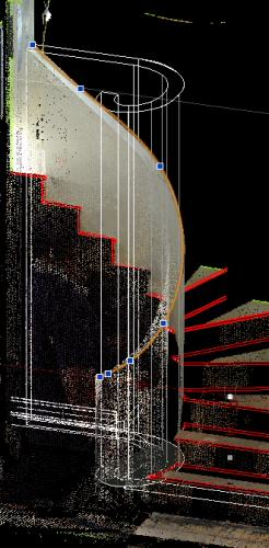
Hi. I've got a head scratcher: I have a laser scan of an existing stair rail, and I want to model closely what is there, so a new rail cap can be fabricated to fit. I can easily trace the edges of the wall in plan view, but when it comes to creating the sweep, I'm stuck. The highlighted object is a nurbs curve, which is reasonably close to the top edge of the existing wall, but doesn't follow the surface of the extrude, as it was drawn separately. The round wall tool works, sort of. If one were able to convert a polyline into a round wall object, then I could probably use the sweep degree to get reasonably close, but because the existing wall was handmade, it will never be exact. I'm imagining there is a way to project the nurbs curve onto the solid to trim it, but I'm not familiar enough with these operations to figure it out. If anyone can point me towards a tool or a technique for this type of geometry, I would appreciate it immensely!
-
Using vwx lock (lck) files when sharing files with Dropbox
mgebel replied to John Whyte's topic in General Discussion
Does anyone know if there any update to this since 2014 in the way that VW and dropbox interact in Multi-user environments? I am interested, because we are beginning to move into a more advanced multi-user modelling phase at my company, and I am interested in learning some best practices for avoiding frustrations. Of course, we are looking into Project Sharing as a main method, but this is problematic for certain projects that use incompatible plugins (interiorCAD, I'm told, is one of them?). Moreover, there are circumstances that we have have legacy projects that have not been setup for PS, yet, and we want to be able to toss them back and forth. Where I'm at now is simply confused about when exactly a .lck file is generated over Dropbox, and how I can avoid problems when sharing files with other users in the cloud? -
A brief update, I went through all of the export settings, and I converted the object to everything that I could try, and the segmentation problem in the DXF persisted, that is until I stumbled across a wiki about how DXF files work, wherein I discovered that the text version of DXF is more robust and accurate than than the binary version. It turns out that was the one setting I don't think I had tried previously, so I went back to my original polyline and exported to DXF text, and wham-o, perfect polyline curves came back. I still have yet to hear if my neighbor's machine is going to bug out again, but I have my fingers crossed. So my next question is, why would one ever want to export to DXF binary?
-
I feel like this should perhaps be it's own thread, but problem is primarily AutoCAD failing to interpret VW 2D line objects (if not, VW failing to convert them properly...), and it also happens that I am also working on an arch... The specifics: I want to export 2d objects to DXF. I have some parts that I would like to have cut on my neighbor's CNC, which is running WoodWOP. His typical workflow involves drawing his parts in AutoCAD, then converting the DXF files to Homag's .MPR format using another program that adds on all the g-code and tooling parameters. I sent him a DXF export of the parts, which include a polyline that containts many bezier curves, fillets, as well as circles and 2d Loci. I tried exporting in all the DWG and DXF versions, but it always converts the polylines to "splines" which has the faceted problem (Neither of us knows what a spline is, but I am guessing it is what VW calls polygons). This is problematic especially for CNC, which requires that angles be outside the radius of the tool path. I had this issue with the complex line, but oddly I also was unable to get AutoCAD to register the circles as DWG/DXF circles - they apparently generated a group of arcs, instead. This problem was solved by adding the locus point, which serves as a drill center rather than forcing the circles convert accurately (the locus becomes the drill center and the arcs are ignored). I have attached a short clip showing the mouse wheel zooming in and out one click on a 3/16" fillet on an inside corner. I have the display graphics set at Best Performance, and I'm running a fairly capable machine, plus these are 2d objects. I am guessing that when it flickers on and off, it's a glitch in the VGM, but I don't know much about how that works, so it could be something else. Also, it flickers on zoom in TOP/Plan, but is off all the time when viewing the object in the 3d plane (pictured) This could be the same issue when you zoom in on a polyline that is selected, and it shows the orange highlighted object line with facts instead of smooth curves. Bottom line, though, I don't especially care about the VGM performance (at least in this context), unless it gives me a clue as to why the export module is having trouble accurately converting these lines into compatible geometry in DWG. Does anyone have any ideas about how to workaround this? I was thinking of possibly trying to convert to a different object type, but I figured I would attempt to draw on past experience before jumping down the rabbit hole. Maybe Nurbs or something else? Is it possibly because I have "Flatten 2d graphics" enabled in the export settings? My next step is to try InteriorCAD for exporting this part. Does anyone have experience with using InteriorCAD for custom3D parts/DXF export? Vectorworks Designer 2020 - [Arches.vwx] 2020-02-03 20-32-16.mp4

-
There is a shortcut for Convert to Generic Solids, which is (win) ctrl+alt+shift+h.