sragan
-
Posts
4 -
Joined
-
Last visited
Content Type
Profiles
Forums
Events
Articles
Marionette
Store
Everything posted by sragan
-
2019 strange glitchy behaviour - disappearing geometry
sragan replied to David S's question in Troubleshooting
Tamsin, the Unified View setting seemed to address both of these problems somehow. Thanks for the quick fix! -
2019 strange glitchy behaviour - disappearing geometry
sragan replied to David S's question in Troubleshooting
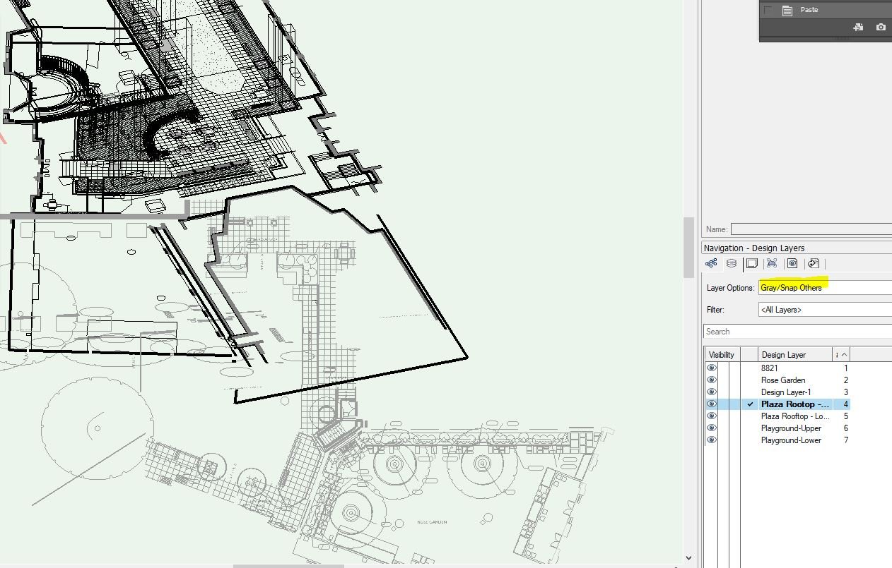
I've also been having a couple issues with glitchy display behavior along these lines but unsure if the causes/solutions are the same. The issues occurred with version 2019 and appear to continue in version 2020. I checked my graphics card and it is operating without issues and has the latest updates. For reference, the file size is about 78 MB. Here are the issues: 1. After working in my file for a few minutes and clicking into either a "saved view" or directly onto a design layer, only the active design layer will appear, even though the layer options are set to "Show/Snap/Modify Others". When I move my cursor over the missing site elements, they become highlighted but are otherwise not showing (see snapshot attached). Also note the blue screen background that sometimes appears with this problem but not always. The only way to correct the issue to set the layer options to "Active Only" at which point the graphic display shows the information I am asking for without the blue background. That said, when I pan the view of the screen with layer options set to "Show/Snap/Modify Others", the graphic display corrects itself (correct design layers showing w/out blue background) but only while panning and goes back blue background with disappearing layers when I stop panning. Note that the lines appearing in the snapshot for some reason are not from the active design layer. I don't have any issues with sheet layers. 2. The other issue is that when I rotate the model into an orthogonal view, the active design layer's view rotates but other layers appear to stay in plan view. See other attached snapshot.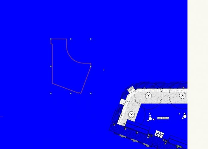

-
Thank you! This is exactly what I needed to know.
-
I am new to Vectorworks and transitioning from AutoCAD so I may be missing some key settings. I am in the process of trying to setup a project base with a DWG site survey and 2 IFC building models to be overlaid together. The DWG survey file is located in the real world (site is around x = 985,140, y = 653,470). I've inserted the DWG as a reference file with "import locations options" set as "Center first import, align all subsequent imports (Recommended)". I now have my DWG located as I would have expected in AutoCAD. For the building IFC models, I created a "host" VWX file to import the IFC file then "referenced" that VWC into my current file. The issue I am having is that the building model loads FAR away (about 4 miles) from the DWG site survey. I am not surprised as I wouldn't have expected the architect's to have worked off a real world insertion point. The same would be true in AutoCAD. However, is there a setting to place the building IFC in a desired location on import? Or easily move it after import? I have tried selecting and moving the referenced building model by using the Move by Points tool but have not been able to move it beyond a very limited distance. When I fit the page to objects (ie. with the model and site survey in the same view) I am unable to move the model by means of any of the tool options, even moving by distance. I can only move it by having a smaller view around the building model and moving it a small distance (a few hundred feet) at a time and the program is constantly freezing (likely due to the fact that I have a working file with 4 miles between elements?). Any insights would be appreciated.