Phileas
-
Posts
206 -
Joined
-
Last visited
Content Type
Profiles
Forums
Events
Articles
Marionette
Store
Everything posted by Phileas
-
@zoomer couldn't have said it better 😶
-
@Boh thanks for your advise, I'll take a closer look at your thread :)
-
@Jonathan Pickup yeah I guess you're right... Anyway this thread will still me personally to get a decent class and layer managing system, so even if my collegues don't use the same files than me at least I'll get more efficient 🙂
-
@Jonathan Pickup Yeah definitely, but in my opinion it can be useful if an office has a default setup file, that way we don't lose time when we have to help out a coworker. So I think having a few default classes and a class library like @Boh suggested sounds pretty good to me
-
@Boh @zoomer In my office, we don't have a default template to work with since every employe uses the program according to his own habits, and so everytime we have to pick up a case for a collegue who's sick or on a leave, we have no f*cking clue of what's going on and we lose a lot of time I'd like to introduce a template with class and layer management that suits everyone, that's why I wanted some information on how other people do it, and both your answers really helped me so thanks guys 🙂
-
Hey everyone I just wanted to ask how you all manage your classes when building a 3D model of a house/building you want to export later: Do you have a class for evry building material? Or one for every component of your slabs/walls? or a completely different technique? what about interior furniture? I'd actually just like to know if there's a universal way to manage the classes in VW Architecture, or if you have any suggestions on how to do it the best way
-
Additional Option for the Extrusiom Command
Phileas replied to Phileas's question in Wishlist - Feature and Content Requests
@markdd Yeah That'd be the dream for anyone doing detailed 3D Modeling, a product designer for example. I know the extrude command works like this in Blender, and I really loved that -
Additional Option for the Extrusiom Command
Phileas posted a question in Wishlist - Feature and Content Requests
It'd be great if we could just manually select a working plane for an extrusion that is different from the original 2D-surface when using the "extrude" command. At the moment, if we want to achieve a volume that looks like the right one named "Loft", we have to convert our surface to a nurbs curve, duplicate it, move it along the Z axis to desired height, select both, and then use the "Loft" tool from the nurbs palette to make them a volume. That's quite time-consuming, having a pop-up window show up when hitting Extrude, with a little checkbox where we can chose to either use the surface of the polygon as a working plane or to manually define another one would be much handier in my opinion, as in Architecture and product design (and anything else that has to work with 3D modelled solids) the extrusion command is something we use very often, and as soon as we're not making something completely planar we lose a lot of time...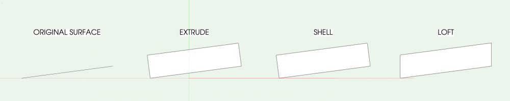
-
@Kevin McAllister Thanks for your answer, I go on and wishlist an extrude command where you can manually select the working plane for the extrusion, no matter the orientation of the surface in the 3D space 🙂
-
@gentlegiant67 I'm not sure about this, but when you go in your section viewport, select the corresponding section view, and then go into the Object Info Palette and scroll to the bottom of it, there's something like "advanced parameters" or "advanced options" or whatever this is called in English. Click on that, an go to "display", there's a check-box for "3D resolution display". I founs that setting this option to "low" significantly reduced the rendering time.
-
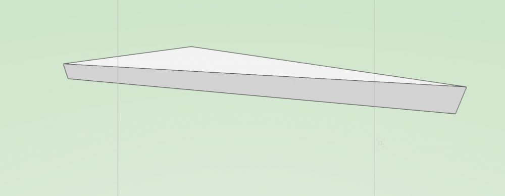
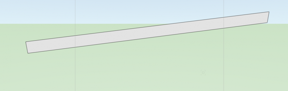
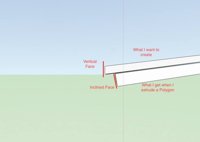
Hey, this keeps bothering me so I figured I'd just ask: Let's say, I want to create this object using extrusions of 2D polygons: It's like an extrude of a sloping 2D Polygon, but it's sides are completely vertical (following the original Z-Axis). If I create a 2D Polygon that's not exactly flat horizontal, like the bottom face of this Volume, and then extrude It, the side faces will be perpendicular to the object I extrude, like this: Is there an easier way to achieve this than just using solid substractions on the sides to get vertical side faces? It's kind of a big miss of the extrusion command that you can't define the workplane of the extrusion manually when you hit Cmd+E, I keep losing time with unnecessary solid substraction...
-
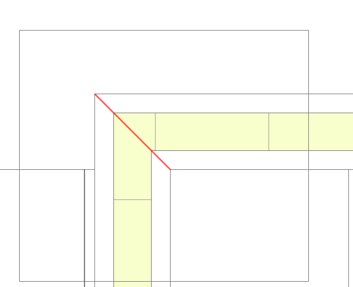
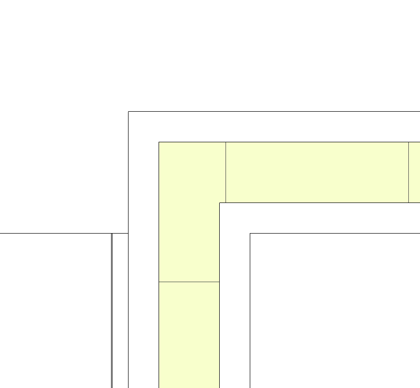
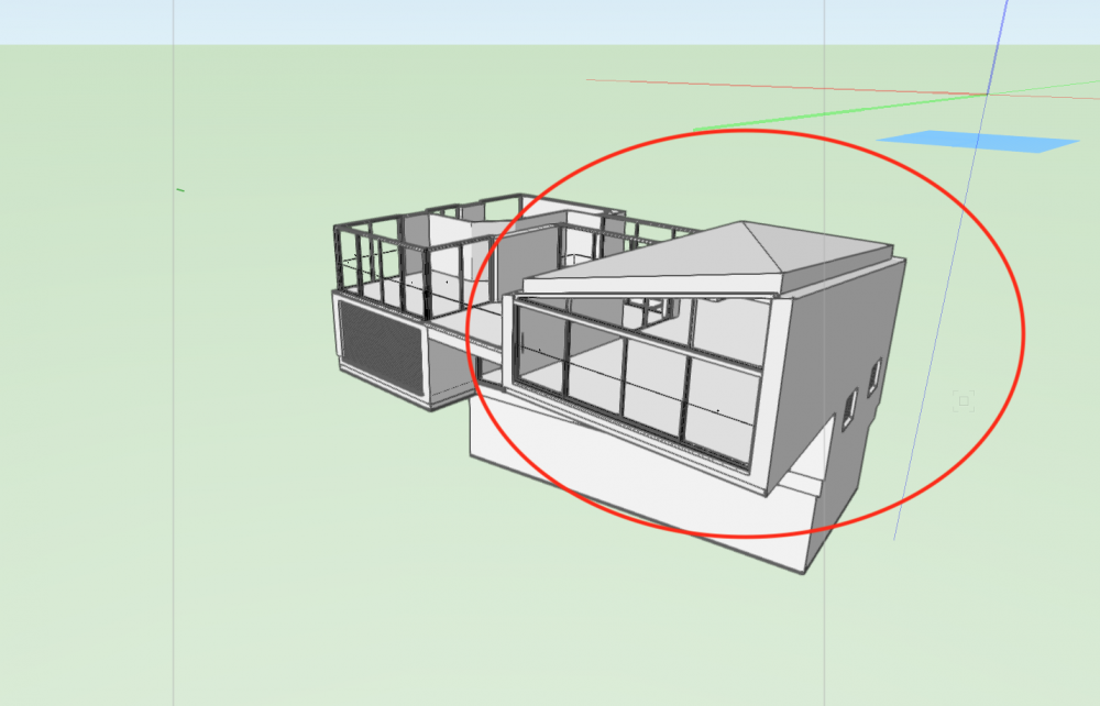
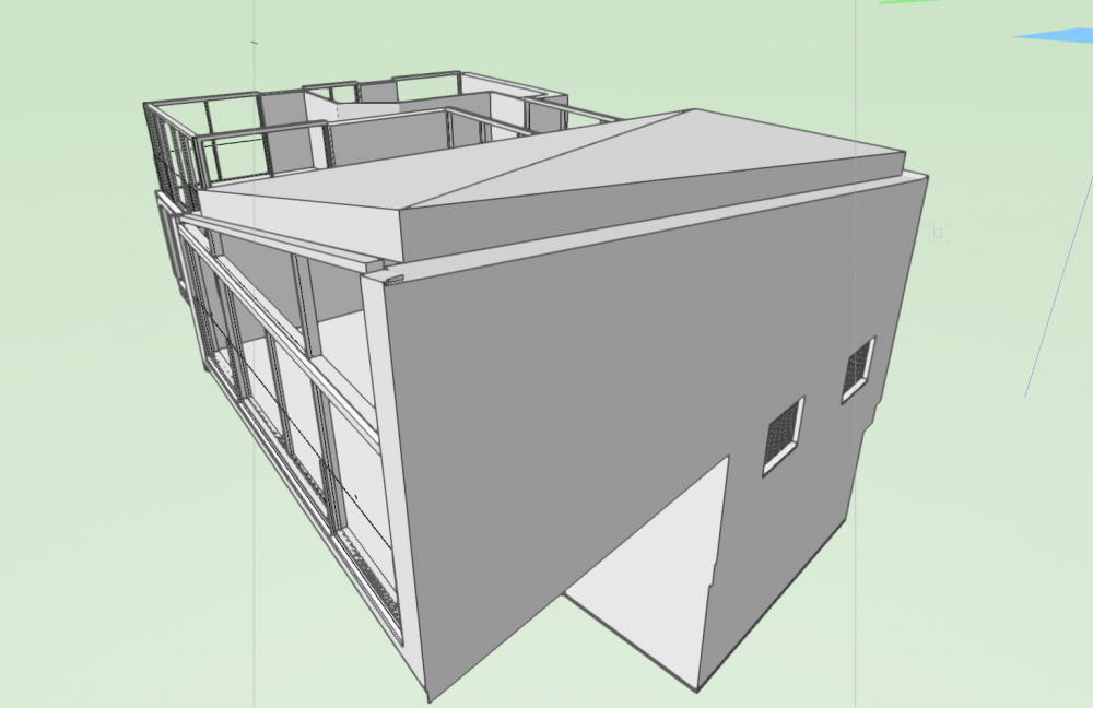
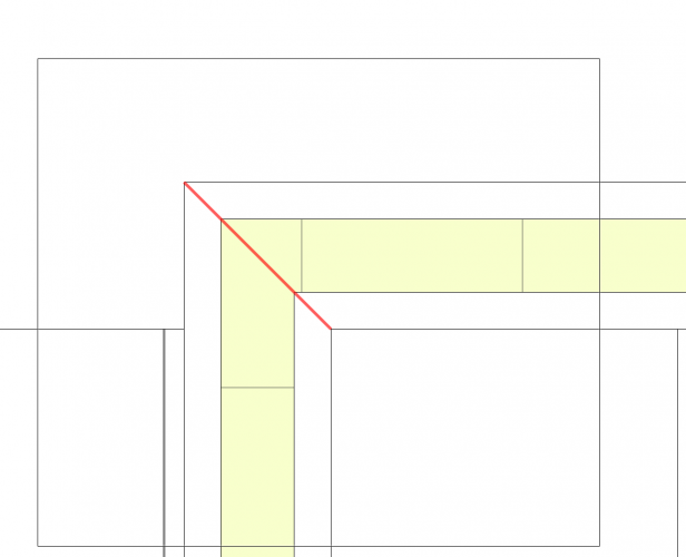
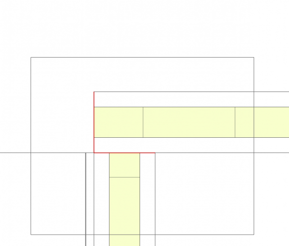
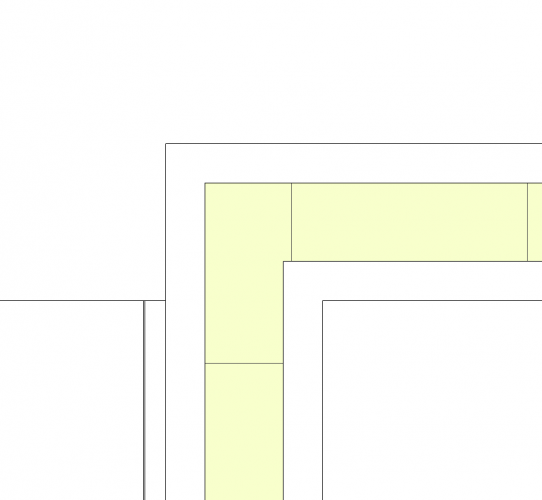
I suspect this has been answered several times, but I haven't been able to find a working solution for my problem... So here's the thing: I have to add an acroterion (not sure of the translation, I'm talking about that part of a roof:) I have no trouble doing that for most of the building, but the intersection of 2 specific walls has really been a pain in the a** to model and I'm stuck. Here's the situation: My Acroterion needs to have a fill when looked at in a section view, so I first tried to use wall styles for it. The intersection of the 2 walls ended up being as weird as the one you can see in my last picture. I then switched to using extrudes (drawing 2D Polys and extruding them, then moving/rotating them, into their final location). I came to realise that it's probably geometrically impossible to have a clean intersection on the upper and lower face of 2 intersecting extruded planes that don't have the same slope without varying their thickness, which would be kind of complicated to do using extrudes since I'd have to use multiple rotated extrudes as solid substractions to cut off the excess parts of the 2 original objects, and that already sounds very time consuming. I then tried to use 3D polygons to draw each face of the shape I want for my finished object manually. That workes like a charm, the result looks exactly like the thing I wanted to create when you look at it from the exterior. However, in a section view, the 3D Polys do not show a fill, even though they form a closed volume (a quite complex one with varying thicknesses but still a clean 3D volume). So my first question is: Is there a way to change an assembly of 3D Polygons that form the faces of a closed 3D Volume into a volume to which you can apply a fill? And If that's not possible: Any other Ideas on how I could solve my problem? The walls do not have the same slope btw. I managed to solve this for the roof you see on my picture. But I had to use 2 different roof face styles with different thicknesses and adjust them millimeter by millimeter manually and that took hours.... I was wondering if someone had a better way to achieve a decent result

-
@jwatson4 I'm not sure about that since I've never done it, but you might want to use a nurbs-curve to follow the outline of your room, and then create a nurbs,surface out of it, and then thicken it. All these tools can be found in the nurbs-tool pallette. Again I'm not sure if this is gonna work or not.
-
@Phileas Nevermind, figured it out. Was simply a bug of the program, restarting it solved the issue 🙂
-
I need your help for a wall join I somehow can't get to work the way I want... That's what I want to achieve. Now I know this looks like I did it, but it only looks the way I want in top/plan view. My problem is that the wall join is not on the part of the wall I want it to be. In my case, I can only get the standard wall join: a diagonal line betwenn the walls. This doesn't matter in 2D, but in 3D the top end of these 2 walls are not on the same level, and I need the separation between the 2 walls to be a clear line like this: So this is where the join is supposed to be, but I can't get the components to join like in the upper 2 pictures. I'm guessing I have to use the wall end cap tool since I did this once and it worked, but now this same tool tells me "selected elements cannot be subject to solid additions/substractions" or something like that and refuses to join the walls in the way I want. Help would be appreciated
-
@jnr That's what I mean when I say that we (the users) actually ask exactly for what we want, but it takes years to get it, even if most of our requests are quite simple in my opinion. Considering the price we have to pay yearly for this program, that's what really bothers me
-
@JMR yeah I feel like there are some small issues like that everywhere in the program, which sometimes gets really annoying... I'm less bothered with these since I work on a mac and never had problems related to the power of my computer (except for the space tool and external references that seems to be buggy for everyone), but I see a lot of people complaining about it
-
Hey guys Some of you might have noticed that I've been posting about quite a lot of problems I've been encountering lately. I'm a new user who switched to VW after working on ArchiCAD during my whole studies, and arrived here expecting sort of an identical program simply with a different name. Maybe that's why I was disappointed in the first place, when I had to struggle with tools I found to be a lot less powerful than the ones on ArchiCAD when I comes to working in 3D. After working on it for a bit of time now, and stumbling over the Marionnette tool today, learning that I can sort of program my own tools with these scripts, I realised that VW doesn't really work like ArchiCAD and other programs of that kind: Sure, it has all the standard tools like the others (and to be honest a lot of them are very poor imitations lacking a lot of functionalities (vertical stacking of walls, simply everything about this awful stair tool, the list is very long)), but it has an incredible amount of options to go a lot further than the other programs: The solid modeling is (at least to me) a lot more fluid than the morph tool in ArchiCAD, and the 3D editing tools allow you to create virtually anything if you invest some time to learn how they work. The Marionnette tool is something that looks quite amazing to me when I look up the staggering amount of things you can do with it if you know how to program (again you'd need to invest a lot of time learning that). Overall I just feel like VW could blow all the other BIM and CAD programs out of the water if they just spent a little time finally fixing these tools everyone is complaining about, it's quite a shame they haven't done it yet and I really hope they simply read this forum thoroughly, cause most of the users tell exactly what changes/additions we are all expecting, it's not like they have to imagine them themselves... Just wanted to put my own 2 cents here, hoping (maybe a bit naively) to contribute to the improvement of this program.
-
@bcd Thanks man that's a nice little shortcut 🙂
-
@zoomer what I usually do to get the top plan view I want when using solids is: model the entire thing in 3D until you're happy with it. Make it a symbol by going to: Organisation -> Create Symbol Drag it into it's final location go to a top/plan view. You should see a mess of lines, because solid extruds have no fill in a top/plan view. draw the 2D apparition you want your object to have on top of your object using 2D polylines or rectangles/triangles/whatever. select every shape you drew cut them using Ctrl+X (PC) or CMD+X (Mac) Right-Click your Symbol and choose "Edit 2D part". You'll arrive to an empty screen, since your symbol has no 2D apparition yet. Paste the things you cut out earlier (Ctrl+V on PC, CMD+V on Mac). Go back to your top/plan view. You might find the 2D part of your symbol placed somewhere on your floorplan where it isn't supposed to be. But if you go to any 3D view, you'll see your Symbol is still placed correctly, only the 2D part is not sitting on top of the 3D one. SO you need to go to a top/plan view again, double-click the offset 2D part of your symbol everything except your 2D symbol will now show greyed out. drag the 2D part to it's correct location and exit back to your top/plan view. Voilà, now you have the 2D apparition you want for your 2D/3D symbol. I know you can convert any symbol directly to an hybrid symbol in the AEC panel, but I often find the automatic apparition oh the 3D symbols to show the wrong lines, or too few, or too many.
-
@bcd HEY man that looks promising as f*ck!!! not at work anymore, but I'll try that on monday and tell you guys if it worked 🙂 🙂 thanks!
-
@David S You won this comment section 🙂
-
@line-weight you're totally right, almost all my windows are solid modelled, staircases obviously too since the stair tool is the worst abomination of this program in my opinion (I think we can all agree on that). But I still want to contribute to reaching that day where the tools will be powerful enough to do everything, and that's the reason I keep posting these days shouting out the headache the tools in this program give me some days...
-
@line-weight lol I do hope so 😮
-
@line-weight Yeah that is probably the best thing to do... still quite frustrating... I hope that one day we'll reach a level of precision with the VW tools that'll allow us to use only the tools and almost no solid modeling