Phileas
-
Posts
206 -
Joined
-
Last visited
Content Type
Profiles
Forums
Events
Articles
Marionette
Store
Everything posted by Phileas
-
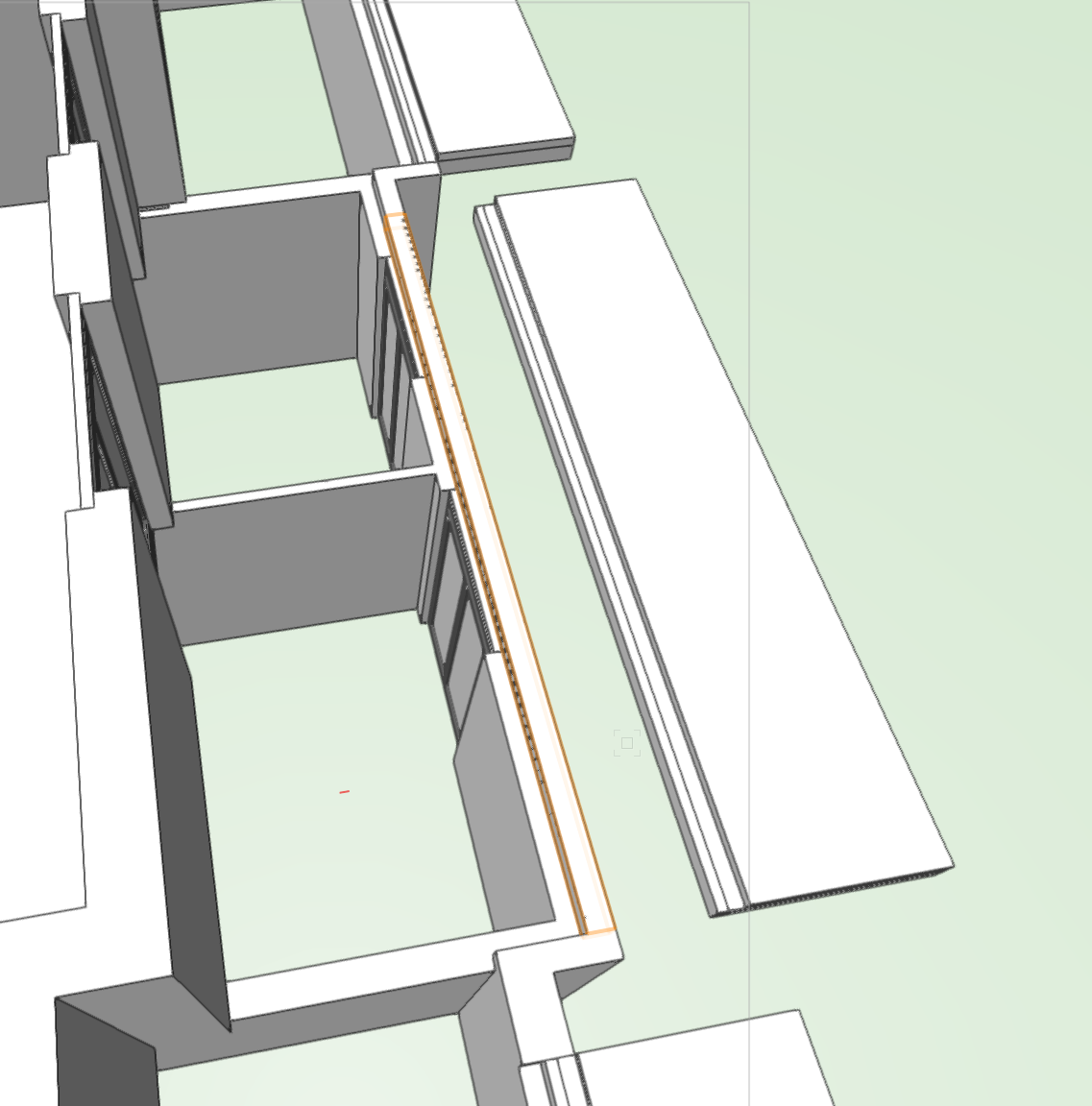
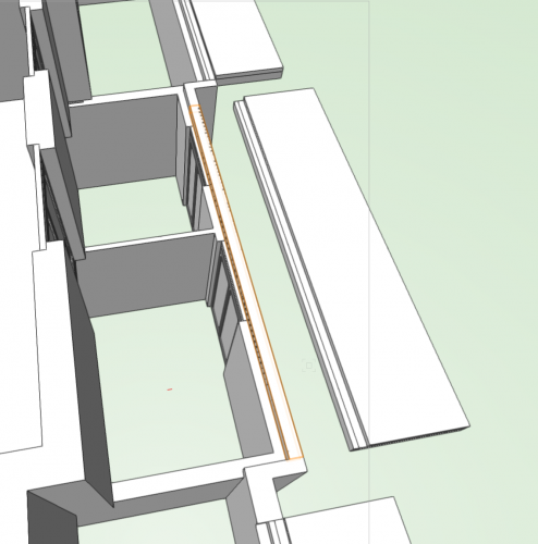
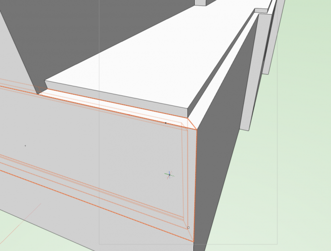
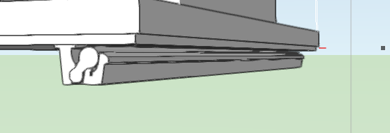
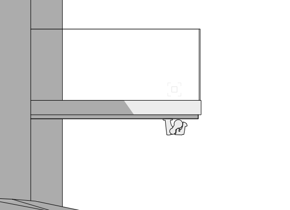
I need to substract the highlighted solid from this wall in order to insert the slab on the right properly. The substraction affects only part of the wall not it's entirety, that's why I can't use the component offset option you can access from the OIP. It also only affects the outer component of the wall. The object I try to use to do the substraction is a simple extrude, and I'm trying to use the "Substract from wall" (ot whatever it is called in english) command of the AEC drop-down menu. I get an error message saying pretty much: "there's no valid object to sculpt a wall selected". But I remember substracting solids from walls in the past just like this and in my memories it worked just fine. Where did I go wrong?
-
@Matt Panzer Yeah I think I can live with a higher smoothing angle.... hope my boss can too... thanks for your help
-
@Pat Stanford OK thanks man!
-
Is there a way to have half of the top end of the highlighted wall fit to the slab you see here, while having the other half fit to the bottom end of the upper wall (left side of the picture) ? I mean without having to make 2 separate walls.
-
@Matt Panzer awesome you added this!! Unfortunately, I'm on 2018, and not the boss of the office, so I can't switch to 2019 😞 Does anyone have a solution for anterior versions?
-
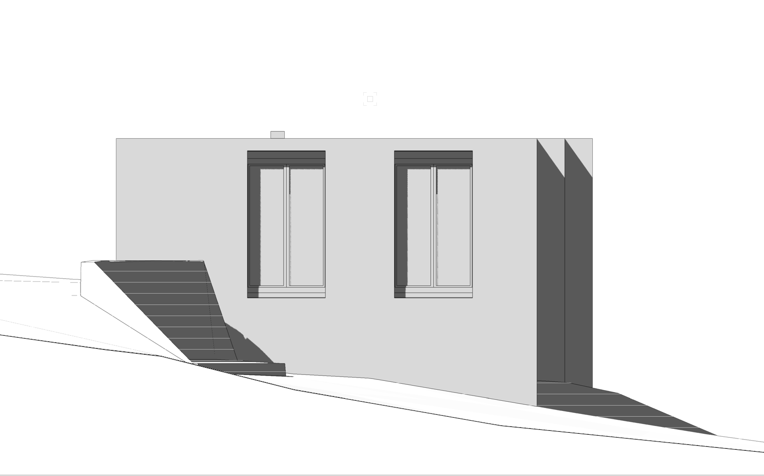
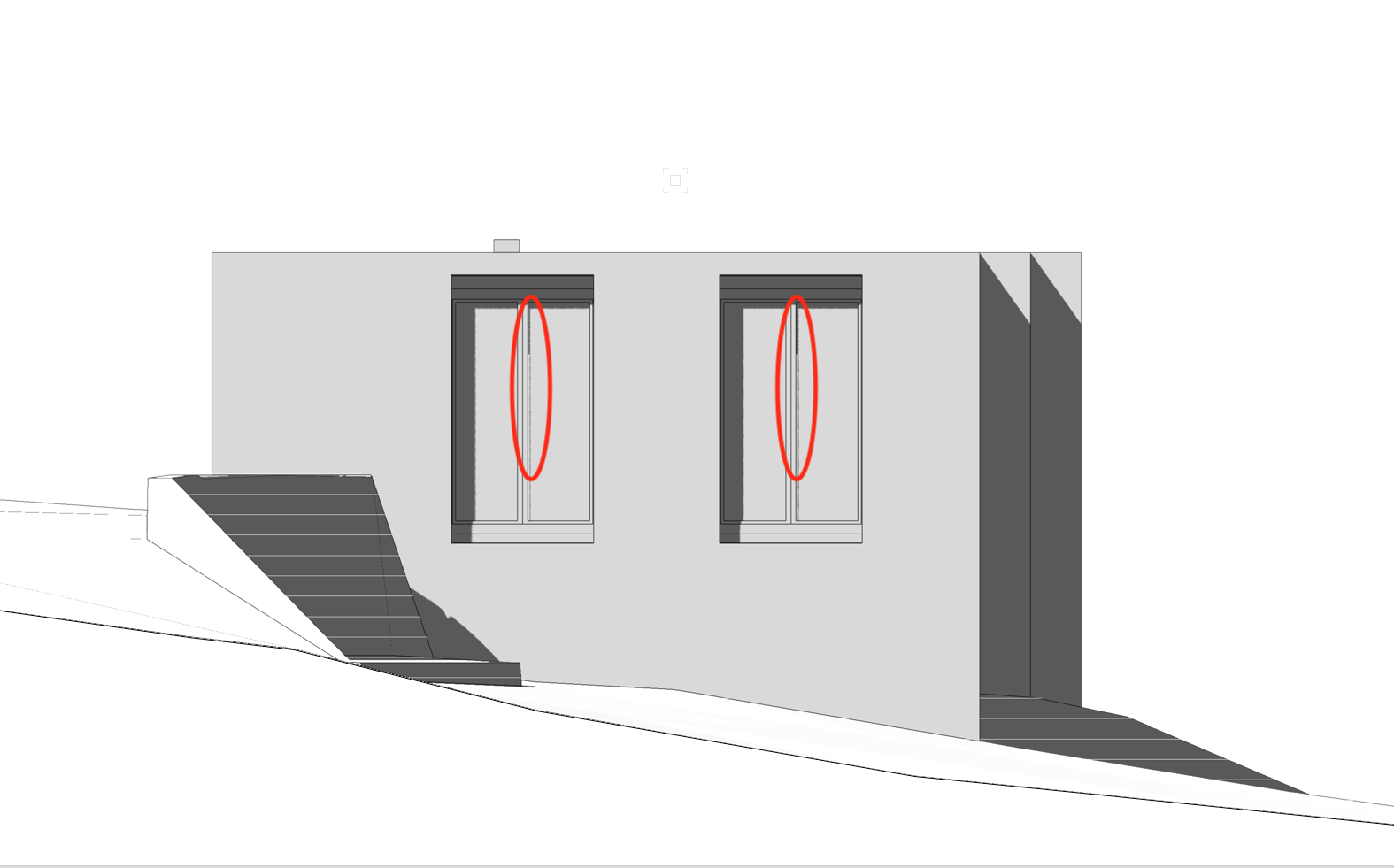
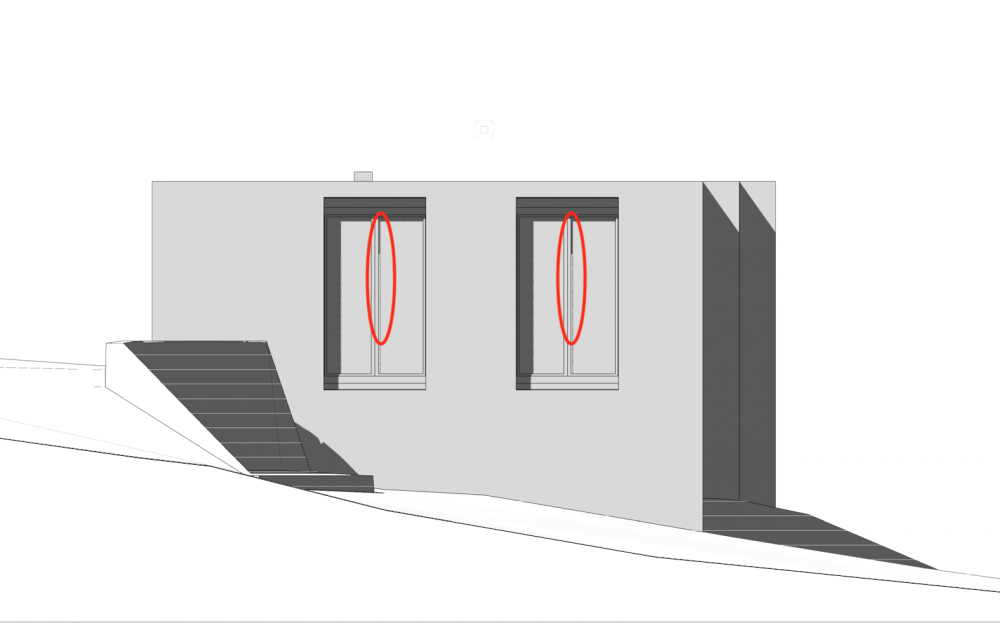
Is it possible to define a different appearance for objects/symbols in a 2D view? My problem: I modeled this window-blind in 3D. So far so good. I know I can adjust the appearance of a symbol in top/plan view by editing it's 2D component. Now, I have a problem with this type of objects in elevation views: from this side, the object shows just as I want it to be. so for this elevation, it works fine. however, this is what I get in a front elevation view. Just a mess of lines. Is there a way I can control how this object will look from all sides? I'd like to have it looking like this (the light gray lines):

-
@zoomer ok thanks!
-
UPDATE: ok so I tried to do all of what you guys suggested, and I still have a few questions: I tried to use Hidden Lines as a main rendering mode, but somehow once I do that I can only chose from a few variations of Hidden Lines as a secondary rendering mode, which makes it impossble to add shadows. Maybe I'm doing this wrong? I use the OIP of the VP to control this. I then tried to use OpenGL, and cranked up the Presentation Sheet's resolution to 600DPI, which solved the problems with the lagging shadows and gave them more defined delimitations, which is cool. To be honest, that looks good to me, personally I'm happy with the looks of my elevations like this. Unfortunately, I'm not the boss on that project, and so I have to produce something that fits my boss' taste 😕. We have always been working only in 2D and I've finally convinced him to let me try working in 3D on that project, since in my opinion we should try and use all the functionnalities of VW. Suiting his desires ends up beeing quite annoying, since he's the kind of guy who doesn't want to have to model more detailed things in 3D (like window blinds and things like that (which is ridiculous since we have the DWGs and just have to make an extrude it takes 3 minutes...)), doesn't want to draw them as annotations of the VP, and still somehow expects them to appear in elevations 😕 I then tried to stack 2 duplicated VPs, the top one rendered in Hidden Lines for a crisp outline of the main lines, and the bottom one rendered in OpenGL for shadows. I then put a white filled rectangle between the 2 VPs, and set it's fill opacity to 50%. Here's the result: And here's the kind of thing I'd like to (and have to) accomplish in the end: I think I'm getting closer... do you agree? Does anyone have any advices for me on how to improve'
-
@Benson Shaw @zoomer I'd also like to ask a question: what is the difference between a directional light source and a heliodon?
-
@Benson Shaw @zoomer ok thank you guys, I'll try all of your ideas and update what works best for me 🙂 I don't know what I would have done without this forum
-
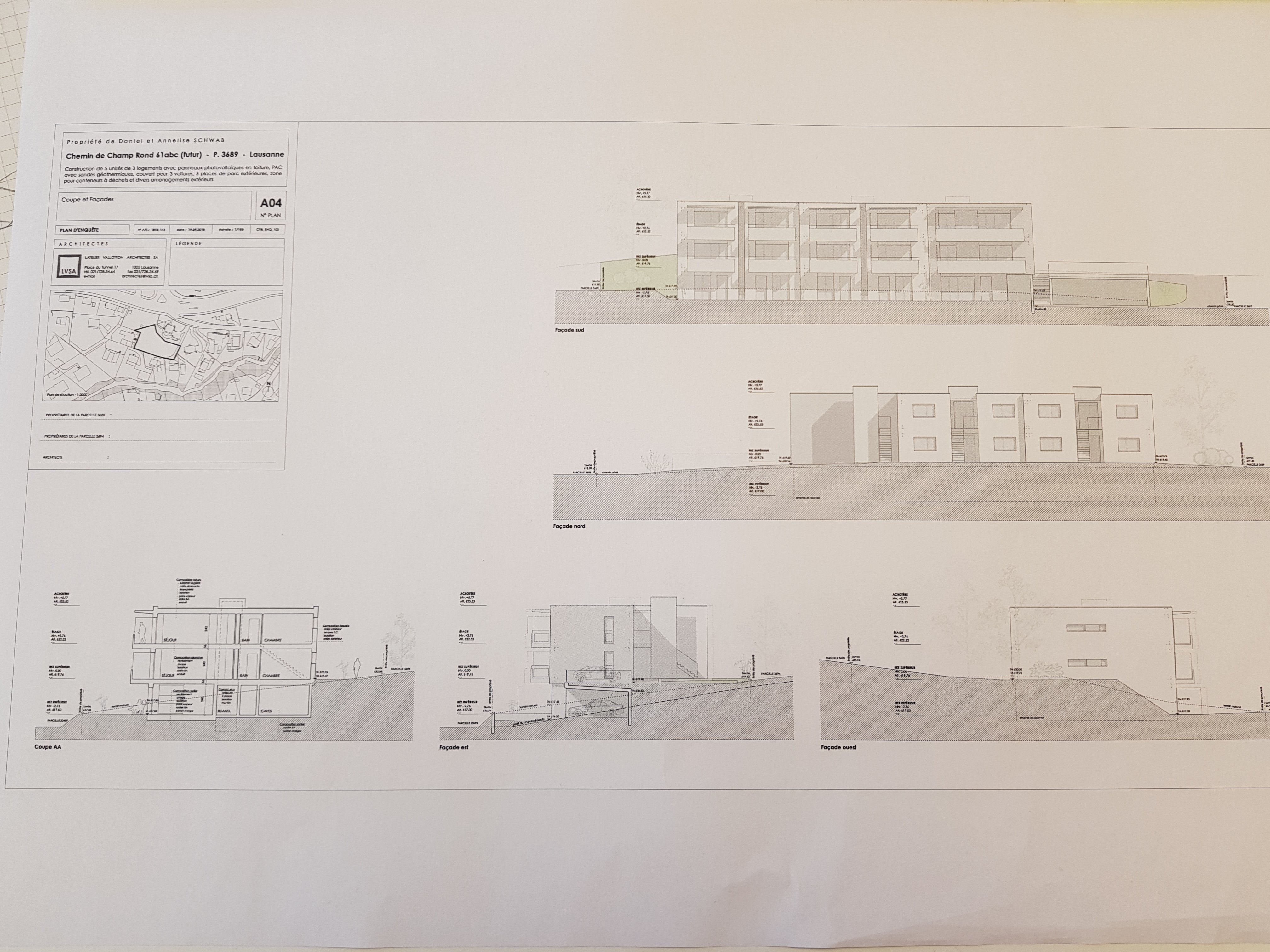
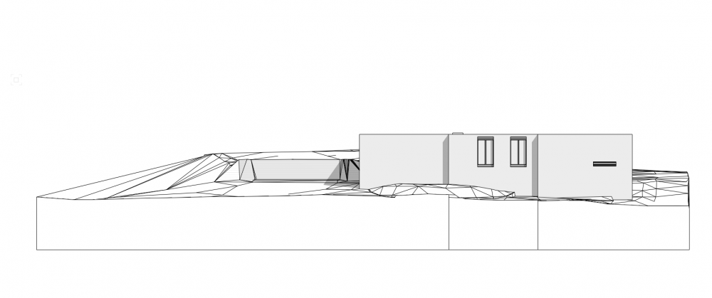
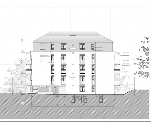
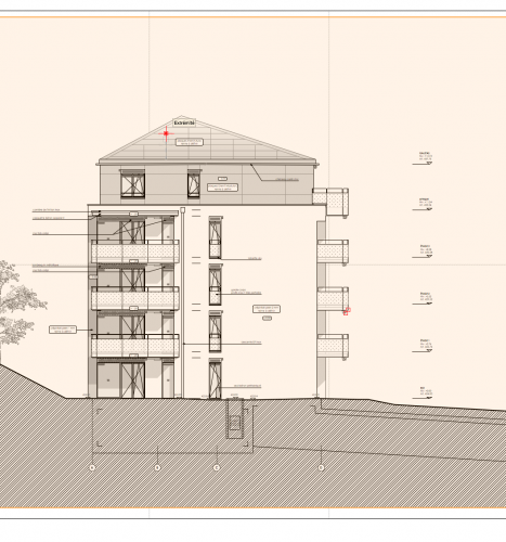
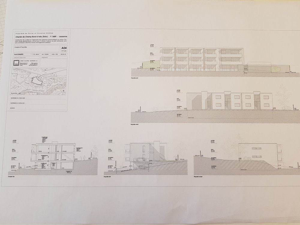
Hey everyone I have a question about shadows in vectorworks: This is what our elevation viewports typically used to look like in older projects: a section viewport cutting through the terrain, showing the building façades. Our office used to only draw in 2D. That means, all the shadows you see on these views are drawn onto the buildings using polylines, gray fill and adjusted opacity. Now, we are switching to BIM, and we have a 3D model of a building and would now like to create façade elevations just like these, respecting our local standards: In all the views, the sun (or light source) is situated at a 45 degree angle from the building. I played with the heliodon tool for an bit, but it doesn't really seem to be the solution to my problem, since I need to have that fixed 45° angle in every elevation view, so I guess I'd need 4 or more heliodons for that (?) I'm guessing I need fixed light sources, but I fear they'll kind of "fight" each other if I have all activated at the same time. So I came here to ask how you guys would do this: would you place 4 heliodons or 4 fixed lights? how would you adjust the parameters of these lights? to avoid them fighting, would you place each lightsource in a different class and activate only the desired one in the corresponding façade elevation viewport? or would you place the lights directly inside the viewports like annotations? Any help on that subject would be really precious to me. UPDATE: so I played around with adding a separate directional light source for every direction of light I want, and placed every light inside a separate classe to be able to activate the right direction of light in every viewport respectively easily. This is the result. While this looks pretty neat, this is not good enough for various reasons. The main ones being: this type of stuff (the lagging shadow stopping in the middle of nowhere): The greyish colour of the walls the fact that I can't really adjust lineweights as clearly as I could in a hidden lines rendering for example. I really like the appearance of the "hidden lines" rendering method for exterior elevations, but I can't manage to add shadows in that mode. Is there a way to do it? Also: I created my exterior elevations by making a section viewport through the terrain in front of the exterior wall. Is that the proper way to do it?

-
@genie I'd like to add something to what everyone else said, concerning the auto-hybrid command: while making your symbol a hybrid one (means it has a 2D (Top/Plan) and a 3D appearance) is the right way to go, I quickly found myself unhappy with these automatic 2D appearances, as I often found they show either the wrong lines, or too few, or too many, but never exactly what I want. So @genie if you ever find yourself in that situation, here's my solution to it: what I usually do to get the top plan view I want when using solids is: Model the entire thing in 3D until you're happy with it. Make it a symbol by going to: Organisation -> Create Symbol Drag it into it's final location. go to a top/plan view. You should see a mess of lines, because solid extruds have no fill in a top/plan view. draw the 2D apparition you want your object to have on top of your object using 2D polylines or rectangles/triangles/whatever. select every shape you drew. cut them using Ctrl+X (PC) or CMD+X (Mac). Right-Click your Symbol and choose "Edit 2D part". You'll arrive to an empty screen, since your symbol has no 2D appearance yet. Paste the things you cut out earlier (Ctrl+V on PC, CMD+V on Mac). Go back to your top/plan view. You might find the 2D part of your symbol placed somewhere on your floorplan where it isn't supposed to be. But if you go to any 3D view, you'll see your Symbol is still placed correctly, only the 2D part is not sitting on top of the 3D one. SO you need to go to a top/plan view again, double-click the offset 2D part of your symbol everything except your 2D symbol will now show greyed out. drag the 2D part to it's correct location and exit back to your top/plan view. Voilà, now you have the 2D apparition you want for your 2D/3D symbol.
-
Best way to create hollow objects with a thickness?
Phileas replied to Phileas's topic in Architecture
@elepp Thanks man, worked perfectly fine! -
Best way to create hollow objects with a thickness?
Phileas replied to Phileas's topic in Architecture
@elepp Is there a command to scale down an object while keeping it's proportions? I have never found it... -
I'd like to know the best way to create hollow objects (Say a cylinder or a cube or a sphere etc.), While still beeing able to give the faces of these volumes a certain thickness so I can apply hatches to them. Anyone who can help me out?
-
Hey everyone, I'm currently working on a building that contains 10 appartements. All the appartements have the exact same layout of interior walls/doors/etc. I'd like to have every story update automatically if a do a tiny modification like moving a door 5cm to the right for example, that's why I made the interior walls a symbol. That's where the problem arrives: when I create the symbol, my walls "Collapse", they show like they have no height... converting the symbol to a group makes the normal height reappear... The height of the walls is defined withing the storys Panel (I have a floor and a ceiling level, relative to each story, bottom end of the wall is set to be floor level and top end ceiling level), and the walls have a style applied... Is there a way to achieve what I want to do?
-
@Kevin McAllister Thanks man, worked fine 🙂
-
Hey everyone, I have a problem: whenever I make a solid substraction from a wall using the AEC menu, the wall then stops showing it's components in a section view, making it look like a hollow object. Is there a way to correct this?
-
@Matt Panzer Thank you very much! solved my issue and helped me understand the mechanism behind it better :)
-
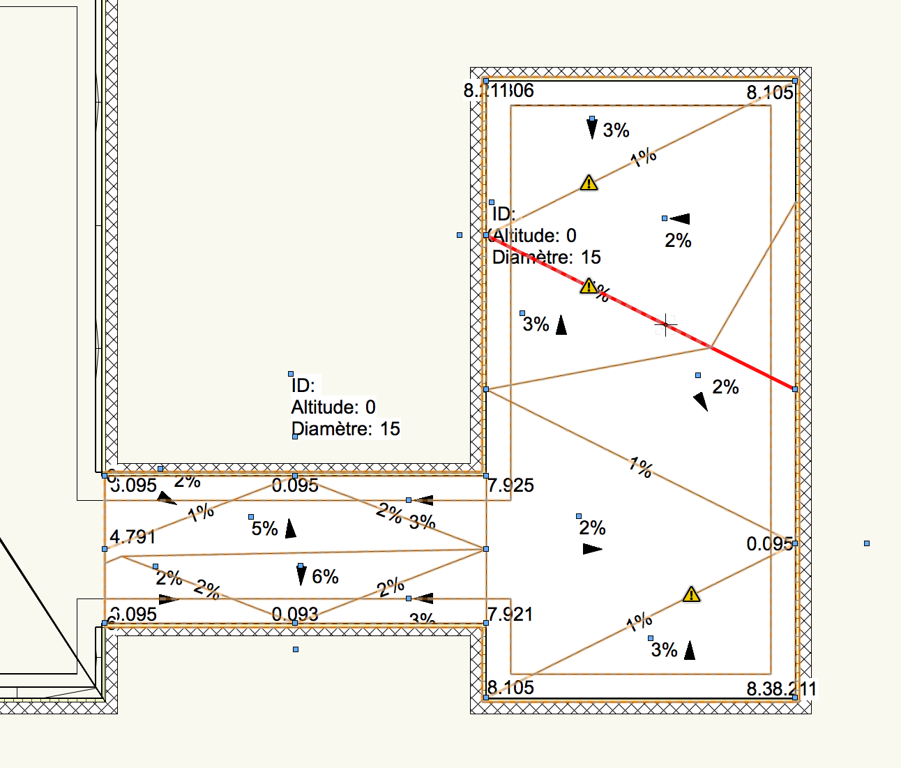
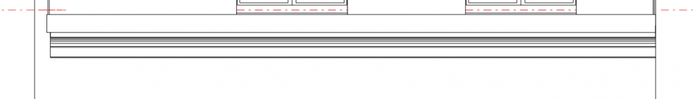
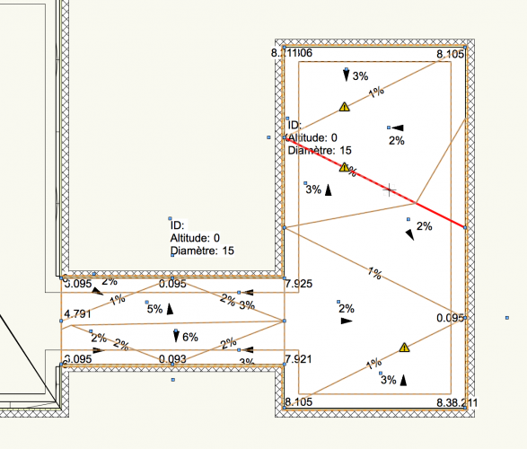
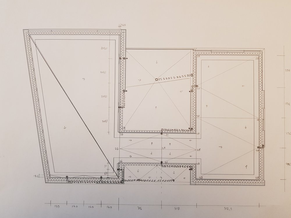
Hey guys me again, and again I'm having a fight with the slab drainage tool. I'm working on a flat roof, and have made a plan on how I want the water to be evacuated from it: (The left wing's roof is pitched, so ignore it) This is what I get when I try to replicate my plan. Every line is attached to it's final location and height as you can see with the highlighted red one, but the tool keeps making these lines up itself, and they don't have a handle at all so I can't edit them. I know I could just keep it like this, create a symbol out of my roof and redraw my plan as the 2D part of that symbol, but it'll still look wrong in section viewports. So if anyone has a solution to make the tool do what it is supposed to, please help me. I don't really have the time to create these slopes by hand with solid substractions, since I'd have to adjust all the components of that roof slab above the sloped one manually as well.
-
@Jonathan Pickup Thanks mate, I'll have a look 🙂
-
@Rossford could you give the link to said video? I'd be interested in watching it!
-
possible to import 3D Objects made with Blender into VW?
Phileas replied to Phileas's topic in General Discussion
@zoomer @MRD Mark Ridgewell @EAlexander I don't have blender on my working computer, and am unfortunately not allowed to install things on it since it's my office's property, but I have blender on my PC at home, I have to export some files and send them to my E-Mail so I can import them to VW the next day at work. I'll gladly give some feedback on how I get along with the different options you guys offered when I checked it out! @zoomer I also fear that a DXF file would only import lose geometry... I'll try it out tho -
possible to import 3D Objects made with Blender into VW?
Phileas replied to Phileas's topic in General Discussion
@MRD Mark Ridgewell I'll give it a shot, thx man! -
Hey I wanted to know if it is possible to import 3D Objects I modelled in Blender into VW, and if that's the case, how you'd do that