ryanww
-
Posts
44 -
Joined
-
Last visited
Content Type
Profiles
Forums
Events
Articles
Marionette
Store
Everything posted by ryanww
-
Glad I'm not going crazy 😛
-
@Nikolay Zhelyazkov sorry - link didn't paste. #1 - https://watch.screencastify.com/v/QBuYk4357PsoAnNYpXcb #2 - https://watch.screencastify.com/v/OB7NVwvyMmtPCksxtqk8 I added a second video too. In the second, I had deleted the rack and pasted the rack from a backup. It keeps the layout in tact. But the items aren't associated, even though they have the same name. I can temporarily change the name then back to the original name, and that re-links the rack item to the schematic item.
-
@Nikolay Zhelyazkov Here is a video showing the copy and paste. I messed up the first bit, sorry, but 2nd attempt shows the rack layout get reset if the rack gets copied and pasted. Originally I did this because I made a new layout layer and so I needed to move it to the other layer. I just cut and pasted. Even here, I cut and pasted, and the layout didn't come with it.
-
@Conrad Preen I get that, but a rack frame that has slots will always visually resize a device to fit it, and a tray acts the same. So with this, a visual resize makes sense in my opinion.
-
Another bug. If I have a rack tray (love that!) that is resized with equipment on it, the shelf shrinks from the bottom to top. Devices remain the same size, but don't move up.
-
Another bug to add -- coping and pasting a rack wipes the rack layout. Copying from a backup file of the same rack brings it in with the same layout, but the devices are not linked to the schematic devices.
-
@Nikolay Zhelyazkov @Conrad Preen sorry, didn't get an email that you had replied. Attached is a slimmed-down file with just the rack views. There is only one sheet layer with this, so you can spot it right away. And I understand. But as feedback, it's rough on the user end when there really are no details on the new releases, especially when there is a drastic change like this. Another point is that while ConnectCad is just lumped in with spotlight, there isn't an easy way to search materials between the two. It's an entirely different workspace, so it's always been odd that it's not an independent category on the training video side. VW Test.vwx
-
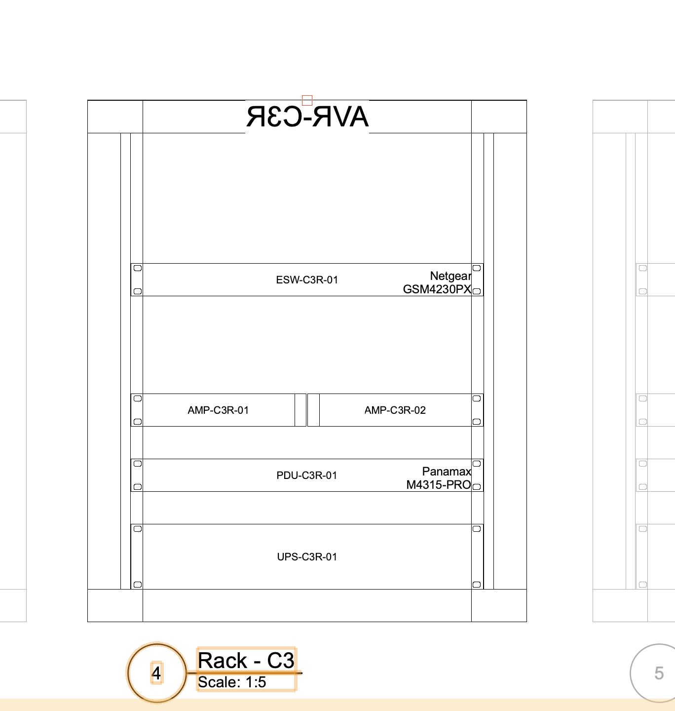
I'm on the fence on how this whole new 3d rack layout works. When I flipped the racks up on end in the viewport, the labels go wonky on things. They flip back and forth between seeing the rack's front and back, so the label almost always shows as backward. Maybe someone can make a short video recapping the whole new rack experience and on how to properly export views from the layout views onto sheets with viewports. The help files for this whole redo are pretty useless in my opinion. I had to figure a lot of things out just by playing with it.

-
Checking the "summarize items" checkbox did it. Thanks! Another question - can circuits be flipped? I'd like to be able to filter by source or destination since what I mention next isn't there right now. Feedback: I'd love to see this be more of a multi-option dialog box to allow filtering by a destination or something. On my drawing packages, I usually split viewport pages up by a cable type, so I had to run everything for the cable sheet and cable report and delete all of the annotations I didn't want, which gets convoluted in a complex drawing. It also seems once the cable sheet is made, none of the data actually ties to data objects, so if a name of a drop-point is updated, the text above it doesn't update.

-
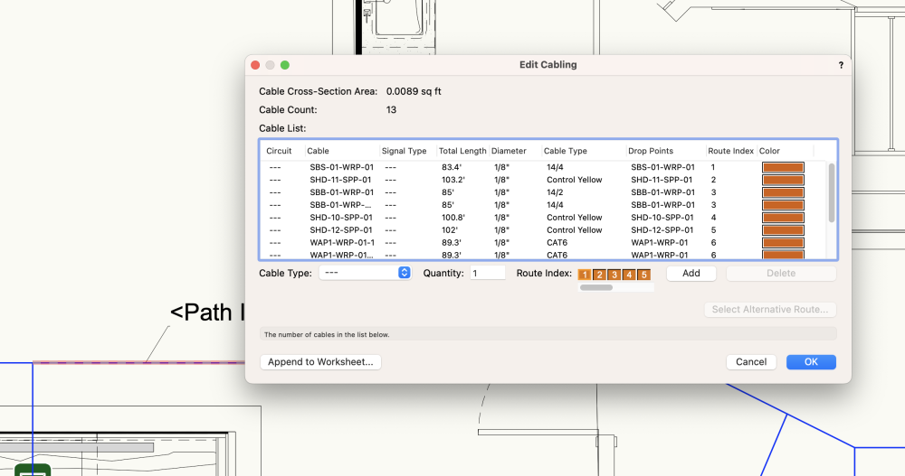
Hello, I'm running a cable pull report using the "ConnectCAD > Documentation > Cable Pull Report" menu item. The line mid-way down that has a qty of 2 is comprised of 2 different cable types, 14/4 and 14/2, it seems to be summing by quantity in a location and not accounting for the type field. How can I make sure every cable type is listed with the lengths here? Seems like a bug to me.


-
Thanks @Nikolay Zhelyazkov - I found that record now attached to the cable paths. The documentation around this is still pretty slim, and where it does exist, it is rather basic.. It would be great to see more videos on this up in the training site, and it would be nice if those can have a filter to explicitly select ConnectCad videos/courses, as they get buried in the other random courses.
-
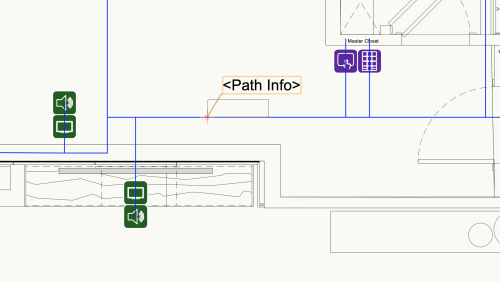
I'm finally trying this whole cable path thing. When I insert data tags, or generate the annotated riser sheet, I am not getting any of the path run data back. Any ideas?
-
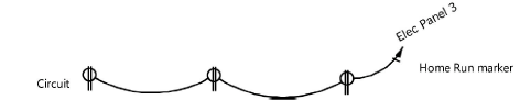
Hey Conrad, Re the below quote - I loaded up the help file and I still don't understand. Since you have made this from the start and been around it every day, it might be a lot easier for you. But for me, as someone who isn't, I just am not getting it. I'm far more visual. There is very little visual anything in the help files. The webinars are great, but there's literally one for this tool, and its entirely 3d. As stated before, I need something purely 2d. Quick easy data. For the below, I don't need to know exactly where the cables physically go, nor do I find an absolute need to have it within the data set as a whole. Honestly, if you used something like the cable "connect tool" with the "arrow" format, that would be great. Really - the Circuiting tool is almost exactly what is needed, with some modifications to work within ConnectCAD. Look at the below pic from the manual. That would be perfect. Yes, but that doesn't get me a break in/out without having to basically create a "device" - unless I'm missing something. Would be nice to have something that is kind of built to be just this where it's easy to have a break in/out. without having to custom make a bunch of things and it virtually knows its individual cables wrapped under one jacket.
-
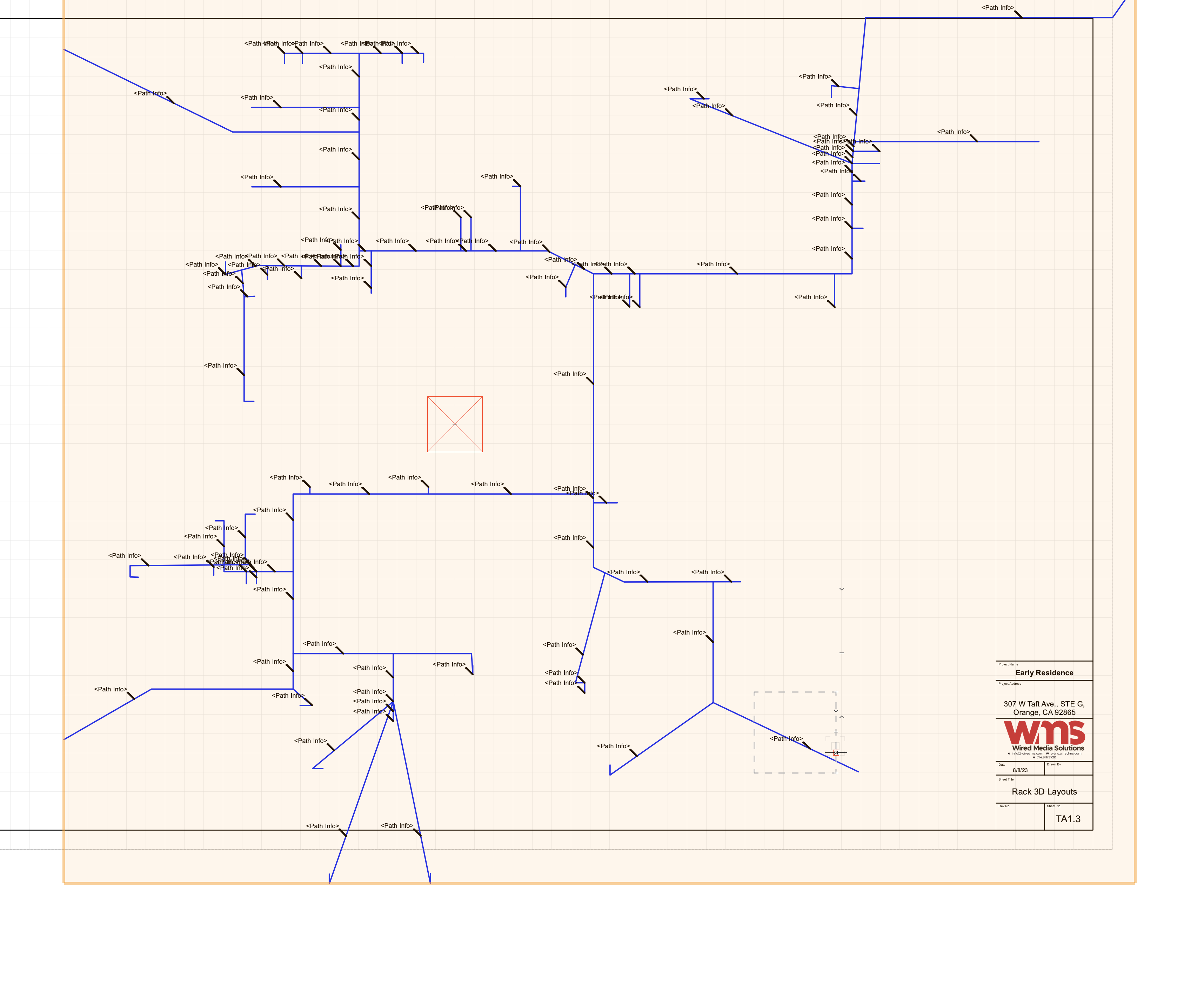
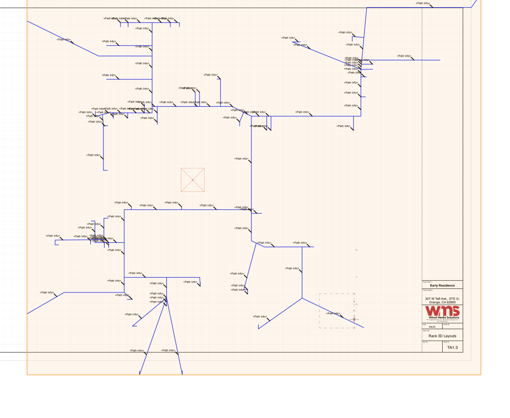
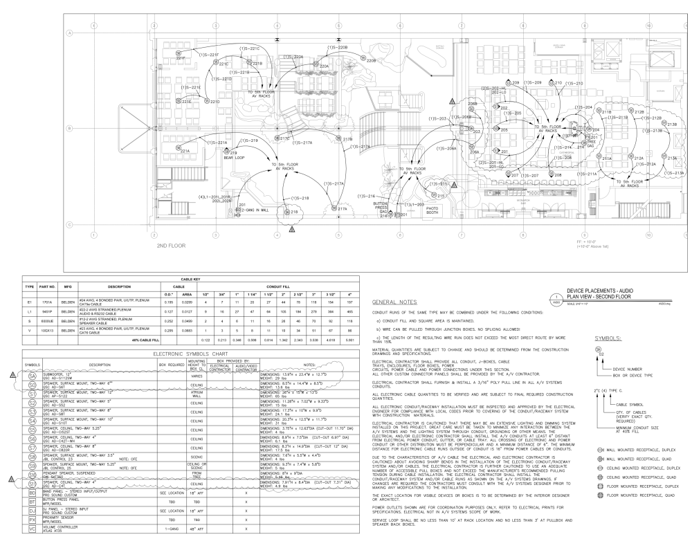
Hey Conrad, The physical cabling aspect of ConnectCad is something I struggle most. Honestly, I've been really stuck trying to use the cabling tools. The help is super confusing, there isn't really very good training material. But most of all, it really seems to require 3d to have it be the most optimal. We do a ton of jobs where we only have 2d, and the time just isn't there to make it 3d. Most of all, I just don't find I need to know every part of the path. Attached is a screen shot of a project we took over and are updating. This was the set of plans we got from back in 2014. As you can see in the drawing, there isn't a ton of detail. Yet, the detail on this page lists just about everything I'd need to know. If anything, I'd just like a way to make this. I'd assume the cable type can be called out in a data tag from the cable it self. But the cable pointer should point to either the location, or the name of the cable. Or maybe a combo. I know there is Electrical and Communication Circuiting which can kind of do this, but it really doesn't tie back to the data in ConnectCad. Maybe it's possible, but I get real lost trying to figure this out. If it is possible, I'd love to see some examples or something on how to do it. If not, I'd love there to be a way to do it. In any event, I feel like ConnectCad piggy backs so much on the "entertainment" side, and really leaves a lot to be desired in the "permanent install/architectural side" when it comes to this. Even if they are the same tools, the nomenclature is quite confusing. As a side note, it would also be great if there was a feature to support a multi-type cable. For instance, we use one cable a lot that has (1) Cat6A, (2) Cat6, (1) Fiber, (1) RG6. Those are all kind of different cables within one jacket, or wrap. Even if there was a kind of virtual break in/out interface. Hopefully I didn't drift too off-topic.
-
@Conrad Preen Alright so I've been playing with this a little bit. I've figured out what you are talking about and was able to link an equipment item and a symbol. Have a couple questions: 1) can I link text from that symbol to data from the original item? I tried setting the text to dev_rec->name but it doesn't pull the data from the linked object. Guessing maybe it doesn't inherit right? 2) I'm completely lost on the cable / cable route / drop point tool. I read through the manual and the documentation doesn't really make sense to me. A tutorial video would be awesome. It certainly is a significantly more powerful tool than what I am really looking for at the moment. My biggest thing right now is probably what the architect symbol set does for wiring in lighting fixtures. I don't want to calculate lengths, just draw the lines but still have it be smart.
-
@Conrad Preenbasically something like this: https://cdn.shopify.com/s/files/1/1142/1104/files/reflexted-ceiling-electrical-sheet_grande.jpg?10870220850097342311
-
Sorry - reflected ceiling plan. Essentially just a 2d flat plan of the house with 2d symbols of locations of devices and such. @Conrad Preen
-
Hello, Two questions. 1 - I’d like to start doing RCP type drawings with the devices we’re using in connectcad. I’ve been trying to figure out how to make a set of symbols that can link back to the device data within the schematics. Mostly names, types and such. Side question with this: do I need architect version to draw linking lines and home run lines for cabling? I see there’s now some new tools but I’ve tried messing around with it and don’t get it. 2 - with the above, can I do this within the same file and add layers for the actual cad or is it recommended/is there a way to link this data to another file?
-
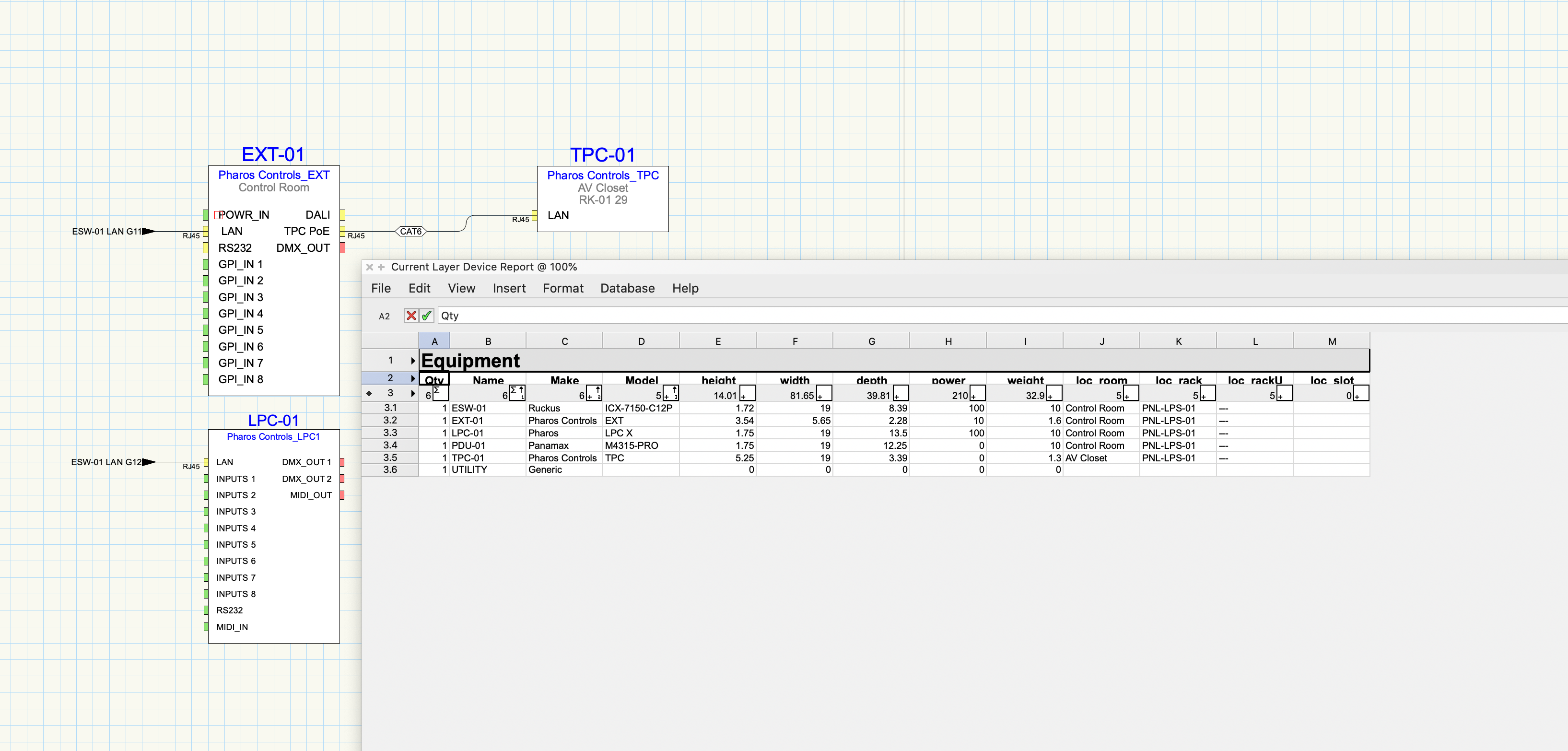
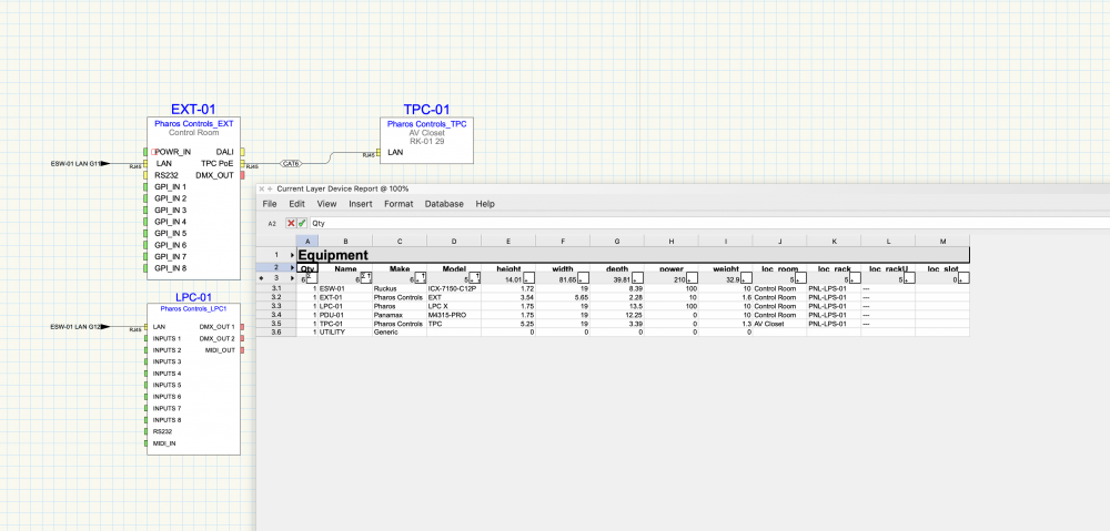
Hey Conrad, There is still some weirdness around the worksheets to the devices themselves.. I updated the "loc_rack" and rack u on the device report and it's not pushing to the devices themselves. I've actually removed the RK-01 reference from the project (no more actual rack, all panel based) and can't get that TPC device to update..
-
Yeah - found them at the base level. Didn't look the other day. Thanks! I think they must have just been left over from 2020. There were a lot of things within this drawing which I had to redo. One of them was any piece of rack gear which I made as a device but didn't set the RU attribute when creating the device. When I updated the rack view, it created a new device on the rack drawing without the settings I manually did on the rack page even though there was an existing one in the same place already in that spot. Another thing I noticed in 2020 was that you can connect to both sides of a data termination panel. 2021 doesn't seem to let you. I have to move a side off temporarily, connect the 2nd part then manually move it back. I'm going to send the 2020 version of this for you to look at.
-
Hey Conrad, I didn't do anything crazy to get there. I did do the majority in 2020 and then converted to 2021 and its had many revisions. So maybe something with that? I did that and looks like the data is correct. However it does not seem to be adding the work sheets back into the resource manager. Is there a way to add them back into there? I suppose I probably dont really need them in there, but good to know.
-
@Conrad PreenSending it now via PM.
-
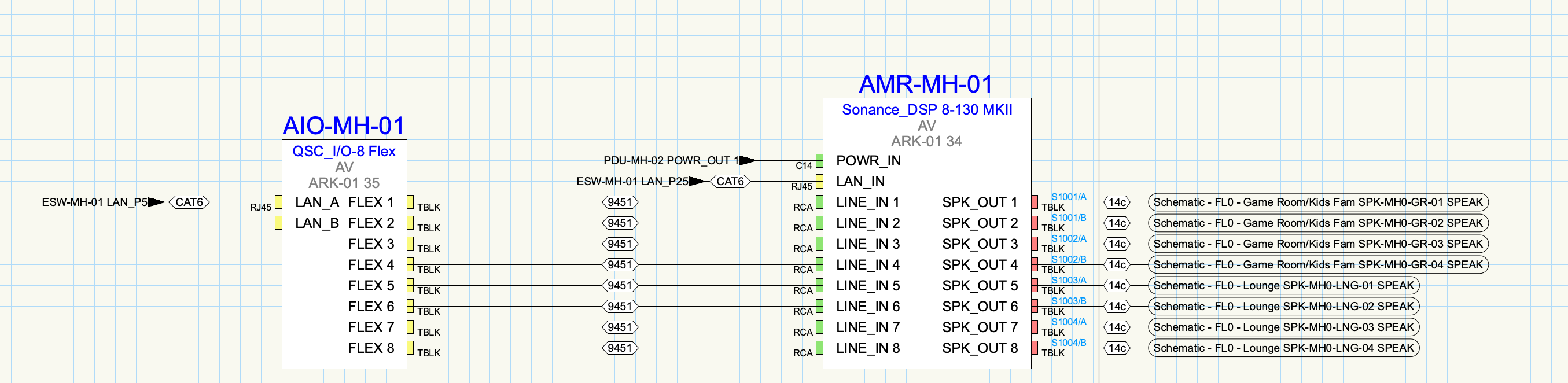
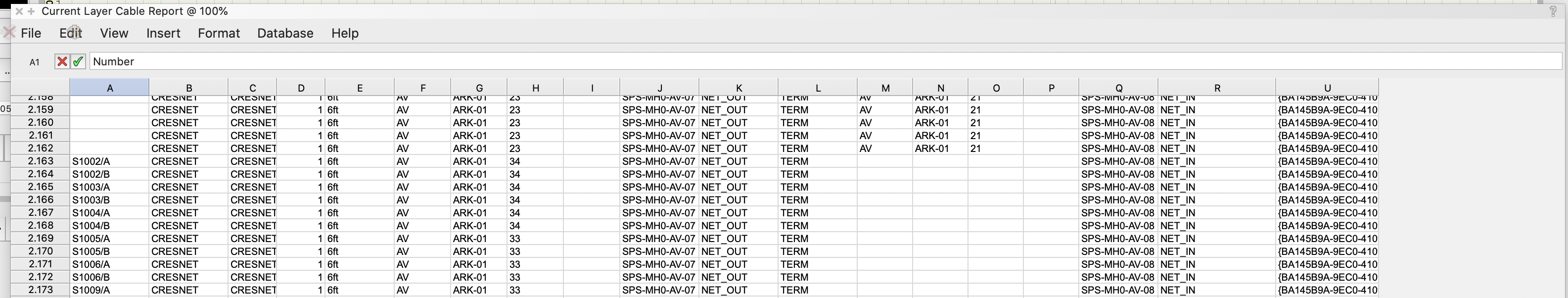
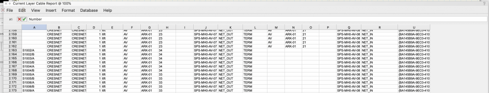
Hello, When running "Current Layer Cable Report", It seems no matter what layer i'm on, its pulling up the same list of source/destination device items with its associated cable type (from a layer not shown/selected), but the Cable number, rack and rack space number is being filled by the shown layers data. Attached is one of the devices and numbered cable sets, as well as the report data with some of these on it. You can clearly see something is very wrong with the data and certainly not lining up with the numbers and associated devices.
-
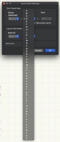
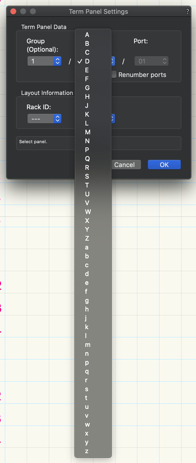
Well its actually missing a few letters which is random. Was this maybe by design?
-
Looks like someone needs to learn their ABC's again 😛 Can't select I as a panel letter. I'm just clicking modify array in properties.